- KINGFIN A new Marblehead 50/800 by S. Witty
- PLANE JANE Part Two of F. G. Draper’s unusual 36 in. yacht.
- Notes for the Novice Model Yachtsman A. Wilcock moves on to the important subject of ‘Balance’
- “RUBBER RUDDERS” George Honnest-Redlich poses some questions on rudder efficiency

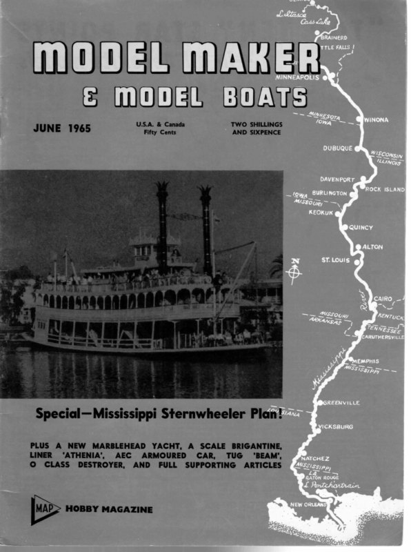
MODE MAK EF & MODEL BOATS U.S.A. & Canada JUNE 1965 TWO SHILLINGS ae Mh. AND SIXPENCE Special— Mississippi Sternwheeler Plan! PLUS LINER O A NEW MARBLEHEAD ‘ATHENIA’’, CLASS AEC DESTROYER, YACHT, A SCALE BRIGANTINE, ARMOURED CAR, TUG ‘BEAM’, AND FULL SUPPORTING ARTICLES Mab> HOBBY MAGAZINE
oon KINGFIN KINGFIN pesicm > 6Y A new Marblehead 50/800 by S. Witty | ae learn directly by way of the Vega concept, Kingfin has a similar configuration and uses the same basic technique for improved performance. The lead is carried at near the maximum draught in the form of a bulb while at the same time the lateral areas are kept high. After experience with the former design and with encouraging reports of the first season of competition coming in, it was apparent that the trend was in the right direction. The only difficulty encountered was that like many ““M” yachts she tended to drive her bows in when running under a full spinnaker. As she is amazingly quick to plane due to her low weight, and what must be the lowest W.A. of any Marblehead, this is of no account once she is “on the step” and the trouble occurs usually in marginal conditions. Apart from this she is vice-free and easy to trim. When draughting the lines of the original Vega and considering how different she was from conventional craft, it seemed reasonable to improve the chances of success by eliminating, as far as possible, those features known to affect balance adversely. Every effort was made to produce a canoe body which, in itself, would have excellent straight sailing qualities as it was expected that the forward position of the fin would increase the weather-helm. Happily this tendency was balanced, as predicted, by the action of the long skeg. Later, it was realised that the concept could be more fully exploited without unduly affecting the balance, and a new and more powerful design became inevitable. First, however, any tendency to drive under down- wind had to be eliminated, and this has been tackled in a threefold manner. The bow waterlines are fined to prevent any wave build up and the height of the stem is raised half an inch. In addition, considerable flare is incorporated in the forward sections. This last affects the shape of the heeled waterline, but is worthwhile in this particular concept to achieve good performance under spinnaker. In Kingfin the hull sections are stiffer and because of this she will tend to point up more, so to com- pensate the area of the skeg-rudder is enlarged slightly. Also, since balance of hull and sail must be regarded as one entity, it follows that the increased freeboard in the forward hull, plus the windage on the flare when heeled, will counter any tendency to point up too quickly in a squall. The sailplan remains exactly the same as that used in Vega. Space is allowed under the foresail should the builder wish to fit a strap. This is particularly worthwhile in a Marblehead, as only the actual area is measured, where as with a 10R or “A” Class yacht 85 per cent of the fore triangle is taken. Thus any space allowed for a strap entails reduction in the actual area of the foresail. The main difficulty is in producing a fitting which can be varied to conform with the luff angle of any suit. If conventional fittings are used, then the foresail hoist of each unit should he lowered anproximately 14 in. otherwise it has been found that the sail is difficult to control if mounted too far above the deck. The ply fin can now be regarded as fully proven and indeed, could safely be made rather thinner. A point to remember is that as the number of laminates is always odd, the grain in the centre is best lined up parallel with the leading edge, and it is not very vulnerable or sensitive to warp at the edges built this way. In Vega a split bulb is suggested, but one wellknown builder achieved a better result by casting the lead in one piece, leaving a 8 in. slot in the upper for’d section for the fin root. One advantage is that the bulb keel is only slightly larger but weighs an extra 14 Ib. Also the fixing of screw or fin is simplified. Screws can be cast “in situ” and then shortened, or holes can be drilled with the fin in position. On the whole, the design shown can be considered a very powerful “M” yacht, not surprising when the distance between the C of G of the keel and the centre of buoyancy is virtually twice that of a conventional hull. Although other configurations for a bulb-keel ““M” craft have been considered it seems that the raked type of fin is probably as good as any other and is certainly more pleasing aesthetically. Builders of the earlier design express themselves as pleased with the appearance as they are with the performance. 232
JUNE 1965 2a Ee = a | a eee i READERS’ MANY readers when writing send in useful hints for other modellers, and some of these are so simple that no drawings are needed. For example, C. Hill of Sheffield got over his dust troubles on wet paint by making three or four wire hoops from galvanised garden wire and connecting these with three straight strips, binding the intersections with wire. The resulting tube was covered with polythene sheet and proved capable of taking most average sized models. Sufficient polythene was left at each end to close off the ends after the painted model was slipped inside. Lt.-Commander A. D. Briggs, R.N., of Plymouth, mentioned a dodge known to many older modellers, but new to quite a number: pin holes in ply, etc., can be removed by applying a blob of water with a paint brush and leaving overnight. The wood fibres swell and close up the hole and normally the hole remains closed when the wood is dry. Sometimes a second drop of water may be needed. This reader gets over the supply problem of thin Perspex or thick acetate by buying a transparent sandwich box from Wool- TIPS worths, which yields a quantity of clear plastic just over jx in. thick and ideal for windows or windscreens. The plastic can be moulded in gentle heat to curves, etc., and should be cut with a fretsaw with a fairly coarse blade, as a fine blade overheats and melts the plastic, with the result that the blade jams in the cut. From Blackpool, S. Starling suggests an old bicycle pump can be modified by screwing in an old tyre valve and cutting off the end to give a larger hole; the pump piston is withdrawn and a second leather washer inserted back to back with the original washer, thus giving a pump which sucks very strongly and is ideal for removing surplus bilge water, etc., from the inside of a boat. J. H. Wilcox of Croydon bolts a piece of thin metal strip to the casing of his soldering iron and in one end of this files a narrow V. Insulated wire can be pressed into the V and given a tug to remove unwanted insulation, thus speeding up the work of soldering up wires in any electrical or radio installation. 233 II)
Wn pinned into the moulds, only along the chines and inwales. When these are set one has to fair up the edges of the three planks by planing the ply to the correct angle. Try not to damage the floors in the process. The remaining two planks are then applied; this time they have to be pinned and glued to the floors in the manner of the first plank. On the prototype all the pins were removed before lightly sanding the hull. At this point the builder gets a boost to his efforts the time has come to take the boat off the frame. The screws are removed and the forward transom block loosened and the boat comes off the board. The transom block will have to be cut off, leaving enough wood to form the deck camber later. The ends of the chines and inwales projecting past the transoms can be cut off and the ply skin trimmed down at the inwales. Also the floors needing cutting down for lightening can be attended to. Floor No. 4 is left full depth to take the fin keel. Draw a centre line down the length of the bottom of the boat, checking by measurement that this is accurate. This line is used to locate the fin and skeg. On the original model the fin was made by laminating planks of spruce, first with the grain parallel with the leading edge and then fore and aft on the outsides. A flat surface is necessary for this operation and a heavy weight applied while the glue is setting. It is as well to cut the rudder outside laminations roughly to the curve of the hull at the garboards— see sketch—before gluing up. Trace off the shape of HE entire skin of the boat is ;4 in. marine ply. The first plank to go on is the top one (or the bottom when the boat is off the frame!) Mark out the ply, leaving about 4 in. large round the outside and about 1 in. at the ends. Remember that the curve of the hull means that the planks will actually be larger than shown on the drawing. This plank is then ‘pinned up’ using 3 in. brass chair pins. These are obtainable from Bonds of Euston Rd. Pinning up means that the pins are spaced out about PLANE JANE every 14 in. being lightly tapped into the ply, so that they stand ready to be driven home after the glue has been applied. This method makes for speed while the glue is setting. It is advisable to draw a guide line around the ply to help position the pins. With the plank tacked in position it is easy to run a pencil round using the fingers pressed against the stringer as a guide. Pins should be driven into the floors in like manner. The bottom plank “pinned up” ready for fixing is shown in Fig. 3 on the plan. The next skins to go on are the two sides. They are prepared in the same manner but these are not Part Two of F. G. Draper’s unusual 36 in. yacht. Full-size plans can be supplied price 10s. inc. post, plan MM 823, from Model Maker Plans Service, 38 Clarendon Road, Watford. the keel and cut out. It will be noticed that the small fillets are glued on after assembly with the hull. The skeg is made from 4 in. sheet spruce; this has to have a groove along the trailing edge to take the brass rudder tube. It is advisable to do this before fitting to the hull. The fin and skeg can now be semi-finished, which simply entails shaping them to streamlined sections. The shape of the lead half-torpedoes should be traced on the fin and this portion left flat. Also it is wise to leave the shaping of the top of the keel until after fitting, when the fairing blocks can be attended to at the same time. The job of fixing the fin and skeg into their slots is a matter of careful fitting, but it is obvious what is required. The main thing to watch is that these appendages are correct in relation to the hull in all planes. If for example the leading edge of the fin slopes back at too acute an angle it follows that the lead will be too far aft and vice versa. On the other hand, if the fin and/or skeg is out of line with the centre of the hull the boat will not sail a straight course. One more easily. can check them in the vertical plane A template can be made from cardboard, and a further check can be made by measurement to the chines. The deck beams are now traced off the plan. Lightening holes can be drilled in these excepting No. 4 which is left solid. This is because it has a strip of gs in. square spruce glued to its aft face. This is bent to the shape of the aft deck camber and provides the location for this part of the deck. The forward and aft transoms can be cambered to 236
JUNE take the deck and then, using a batten, the deck beams faired up ready to take the decking. Finally trim the inwales to continue the camber of the beams. Note there is a greater camber in the for’d deck. The for’d decking has to be made in two pieces which entails fitting a central stringer. This should be an inverted “T” section let into the fore deck beams. 3°; in. square struts are then inserted between the floors and beams at station 2 and 3, to prevent the foredeck collapsing during the fitting of the skin. Fig. 7 on the plan shows this. The hull must now be fitted out before finally fitting the deck. This entails placing reinforcement blocks to take the various fittings. It is important to make a note of the position of all these blocks on a small plan thus, saving doubt as to their position when screwing on the fittings. Drill a hole for the rudder tube using the groove in the skeg as a guide. Make the rudder tube from 7s in. diameter brass tube, cutting and filing the portion that fits along the skeg to a half diameter. Three countersunk screws hold the tube in place, the heads of the screws being filed down flush with a rat-tail file. The rudder tube must be left long enough to protrude through the deck by about 4 in. When fitting the tube the surfaces must be coated with paint or varnish—in fact all such contacts between metal and wood should be made waterproof to prevent water seeping into the wood. Where the tube passes through the hull the joint is made waterproof by filleting with glass fibre both inside and outside. A false deck spreader is fixed between the inwales to support the top of the rudder tube. As this boat does not have a hatch—although one could easily be arranged—the mast step is housed in a watertight box. If the builder wishes a mast slide can be fitted, and in any event a brass rack must be made to fit into the bottom of the box. The rest of the box is then built around it. The bottom and ends of this box are made from ;% in. spruce and the sides from ;; in. marine ply. Make sure the box is deep enough to project above the deck line by about 7; In., as it will be trimmed off flush after the deck has been fitted. Fit the box into the hull in the position indicated on the drawing. It rests on top of No. 4 floor and a block is inserted to support it on the top of the keel (see plan). Two strakes are added to the sides of the box to support the deck; these are essential as they make for a watertight fitting of the deck. The inside of the boat can now be given at least two coats of thinned varnish, making sure it is worked well into every corner. The inside of the mast box can be given further coats to make sure that it is watertight. The varnish recommended for this yacht is Rylard. Do not varnish the top of the inwales as the deck has to be glued here. Mark and cut out the aft decking from ;; in. ply, leaving about % in. extra around the outside. The forward location will be the shelf on No. 4 deck beam, and by pressing down on the pro‘ruding rudder tube, the position of the hole can be found. When this has been drilled the decking will have two points of location. An extra one to be marked and cut out will be that for the mast box. The reinforcement blocks for the deck fittings can now be fixed on the underside, measuring their positions and noting on a deck plan as mentioned earlier. Before fitting the deck give a coat of varnish to the underside. The after deck is ‘pinned up’ and glued to the 1965 inwales and deck beams. Roughen the underside of the deck at these points, when dry trim off the overlapping ply flush with the sides of the boat. Incidentally, lining the deck to represent planks would be out of keeping with this type of boat. The for’d deck has to be made in two halves and fitted individually. It is suggested that the ‘“V” shape for the coaming break-water is cut after the decking has been fitted, which means the for’d decking will overlap the aft decking by 4 in. As the for’d deck has a greater camber, it has a cut out where it meets the decking already in place. The edge of this cut-out is then feathered to a fine edge. The depth of this cut out before feathering is 3/10 in. Pin and glue the two halves of the foredecking in place and when the glue has set cut out the V for the coaming. This cut should be made at 450 deg. as the coaming is raked. The made in two halves and is of cedar or This again is a job which requires fitting an angle of coaming is mahogany. carefully as it is on an angle. Remember water must not enter around this area otherwise it will find its way be- tween the decking. The construction so far can now be cleaned up, including finishing the shaping of the fin and skeg. Fill any blemishes or pin holes and sand to a fine finish. On the original boat, the effect of the rather wide beam was relieved by pinning a strip of mahogany veneer down the centre of the decking, the width having that of the mast-box (? in.) Both [Continued on page 251]
2 oi Notes for the Novice Model Yachtsman A. Wilcock moves on to the important subject of ‘Balance’ Other Factors in Trimming the Feather Having seen how one must estimate what the apparent wind will be in trimming the feather, attention must be drawn to two other factors. The first is perfectly straightforward, the second, in a degree, controversial. In dealing with plain sailing it was pointed out that with a balanced boat on beating trims no helm was needed but, as the course being sailed moves from a broad reach to a run, the mainsail shades the jib from the wind and this unbalances the forces on the sail plan and, without some weather helm, the boat would turn towards the wind. Now this helm is to be given by the vane gear. Anyone who has steered a full-size craft, even a dinghy, knows that some force has to be used to hold the rudder against the slipstream of the water in which it is moving. In the case of our model yacht the water pressure is transmitted back as a force to the feather, and to hold the rudder at an angle against the water flow requires an equal and opposite force to be applied by the feather. One thing that must be appreciated is that a vane feather flying freely in the wind, ie., the wind is flowing equally on each side of it, can exert no force at all. For the feather to be able to exert a force on the rudder it must be set at an angle to the wind so that the wind is “hitting” one side of it—suction will be created on the other and these two effects will enable the feather to transmit a force to hold the rudder against the water. The interesting—and convenient—thing about the angular movement which must be applied to the feather to create these conditions is that it is towards the position of the true wind when you, and the boat, are stationary at the pondside in the process of trimming. This is a bit of luck, but remember it only applies on courses from a broad reach to a run without a spinnaker. Now for the factor which is a little more controversial, and this applies as much on beating courses as on the run. So far in discussing boat sailing we have talked of and assumed that we were dealing with a balanced hull with a sail plan placed over it so that on beating trims no helm was needed. This in turn means that the rudder can be wobbling slightly in the slip stream and that the feather is doing the same on deck. This fluttering is undesirable and it almost certainly means that the boat has to deviate more from the wind before the helm can take effective control, than if the feather and rudder were “biting’’ ever so slightly at the wind and water while on the desired course. This same condition can be experienced on full sized craft, though seldom are they so well balanced, and skippers will tell you that the boat with the wobbly rudder lacks drive and a degree of control. It is not unusual therefore for the sail plan, of even well balanced boats by design, to be moved backwards a small amount—increasing the rake of the mast may be sufficient. The effect of this is to give the boat a slight (and it must only be slight, tendency to head into the wind on the sails alone, This re- quires offsetting by the slightest amount of weather helm. Here again it is a coincidence that the feather movement to give this is towards the true wind position, and this of course applies on all points of sailing. It is sufficient to terminate this discussion by saying start your vane trims by letting the feather fly to the true wind when trimming with the rudder neutral (central), and the deviations from this that you will less you must allow (for the factors above mentioned) come to you quickly with experience, Nevertheit is nice to know what you are doing and why are doing it. * * * | E Sannin. has so far been quoted and defined as it applies to a hull. We must now consider it in respect of steering gears and it is convenient to do so relative to the simple gear we have so far used as our illustration. How it affects the more complicated gears will be covered as they are dealt with. Two things must be clear to all who have read so far: (1) that there is not a great deal of power in a vane gear and (2) that it is intended to work on wind direction relative to the boat’s course and not other forces. Item 1 should be taken care of by using an adequate size gear with an appropriate size and shape of rudder and ensuring that all parts move very freely. The latter point cannot be emphasised too much. A little “slap” or backlash is much more to be preferred than the smallest amount of binding or stiffness. This applies to the rudder as much as it does to the gear—it is all part of the steering mechanism of the boat. Item 2 is taken care of by balancing. Balancing the steering mechanism is therefore the exercise of removing as far as possible other forces which would detract from the efficient operation of the steering. Turn once again to Fig. 18. In your mind take the vane off its pintle, just leaving the rudder and its slotted arm in position. Still in your mind place the boat in a bath of water. Heel it to port or starboard. If the rudder is made of wood it will try to float upwards, while the slotted arm on the top of the rudder post will try to force it downwards. The forward projecting arm is there to enable small weights (a brass nut and bolt and some washers) to be fitted 2A6
JUNE to “balance” the rudder and arm so that when the boat heels when it is sailing, unwanted helm is not going to be applied. If your rudder is made of metal, change it for a wooden one as the weight necessary to balance it as described above will add too much unwanted weight to your boat. These ideas are best thought about in your mind before applying them to your own boat. The next step is to turn the rud- der to one side so that just the tube and scale of the vane itself can be put on the pintle and they will swing clear of the tail, ic., we have taken off the feather and counterbalance arm. Heel the boat and the pin arm will almost certainly rotate downwards. This piece of the mechanism should also be balanced by small weights on the opposite side. When this is done the rudder can be centred and the pin engaged in the slot. The combined mechanism will now be unaffected by heeling. These parts, it will be realised, have a relatively small rotational movement when in action, but their position relative to the axis of the boat when heeling (of which a boat does a great deal when sailing), is very critical from the point of giving false helm, which can so easily be in opposition to the small forces for which we are looking to the feather. The feather and counterweight assembly on the other hand can be turned to any angle through 360 deg. For this reason they must be balanced on their own. To do this attach them temporarily to a rod of the same diameter as the tube and rest the assembly on knife edges as shown in Fig. 21. The counterweight should preferably be about the same weight as the feather. This can most easily be tested on a letter balance. The counterweight is then adjusted with the feather properly set till the assembly will stay in any position it is put. It is then balanced. You will note the comment “ with the feather properly set”. Some feather mountings automatically set the position (angle to the vertical when on the boat) while on others you have to guess the set, usually the leading edge vertical. It will be apparent from the above that if the feather setting is moved the balance will be destroyed. The feather assembly can now be put on the tube and the whole gear is balanced, i.e., the boat can heel when it is sailing and the gear will have no gravitational or flotation vices. Mention must finally be made of the centring elastic and then you fellows with a simple gear like that used in the description can go sailing. The centring line, like a feather flying neutral in the wind, exerts no force while it is central, it only does so when the assembly to which it is attached moves it off centre. Since it is usually the wind on the feather that usually does this and we have already said we are short of power you might ask why put an elastic to oppose it? A fair question and a fair reply would be that if we could have no friction at all in our gear then the slightest movement of the boat in the water would align the rudder to neutral, and the gear on deck, when the light airs leave the boat. But because there is always some friction, sufficient elastic centring effort should be available to centralise the gear under these conditions. To meet this it is sufficient to use the lightest 1965 while. You must realise that it is being achieved by partly neutralising the normal efficacy of the steering. Self Tacking Gears Having mastered the non-self-tacking: gear, attention can now be directed to the self-tacking vane gears. It has already been explained that the selftacking gear primarily does two things (a) to change the vane angle from one tack to the other when the boat is put about without the gear being touched (see Fig. 15). This is most important since it is the racing rule which permits change of tack by “Poling” which stipulates that the lee bow before the tack and the lee stern after the tack are the only parts permitted to be touched if the boat is to be tacked without losing way and not stopped for a retrim. (b) Guying. This was described and illustrated in Fig. 16. You can guy with a non-self-tacking gear of the type used to introduce vane gears, but the action of the boat will be so violent, unless there is practically no wind, that it will almost turn a full semicircle in its own length. This is useful sometimes, but not often. Two terms of jargon have already been used with respect to the self-tacking gear, namely “fixed” and “broken”, and now is the time to define them. A self-tacking gear is spoken of as “fixed” when it is adjusted to be working as a non-self-tacking gear, that is, it is moved by hand to any working point of the scale to determine the course to be sailed and it remains “fixed” at that setting. A self-tacking gear is said to be “broken” when the self-tacking action is in operation and it will move from the setting required for one tack to that required by the other automatically as the hull of the boat is turned through the eye of the wind. Since this facility is only used on close beats the adjustment provided is invariably only over the angle to do this, ie., not [Continued on page 249] ELASTIC FE ig é 2 2 ADJUSTER ELASTIC OCKING CATCH CENTERING ELASTIC | TAIL OF | QUADRANT of shirring elastic. The centring line is also useful when the wind is particularly “fluky” and a free gear would be spinning a boat all over the place following the flukes. To be able to alter the tension of the centring line under these conditions and improve apparent performance under such difficult conditions is well worth HN
JUNE Letitia, which continued in service for many years after 1945 under the name of Captain Cook, but overnight the name Athenia became a _ household word when she was torpedoed on September 3rd in the North Atlantic. Over 100 of her passengers were lost and this event indicated more than anything else that the war at sea was to be an intense and ruthless struggle. Initially the Athenia carried approximately 1,500 Steam from Scrap A. B. Orr describes a handful of useful schemes for steam fans OR some years now I have been interested (obsessed would be nearer the truth) by working model steam engines in general and traction-engines in particular. Like the two writers in the January issue, my workshop facilities are limited when it comes to power tools but I have had tremendous fun in fabricating engines and it is amazing how efficient they can be made after a little practice. One difficulty that usually deters people from attempting traction-engines is the making of the hind wheels. However, here is a tip that has proved successful every time and is both simple and sturdy. Get two tin-lids about 5 in. diameter. Suitable lids may be found on bulk Sellotape boxes or may be had from most chemists who are supplied with drugs in bulk in suitable tins. Mark the centres and, using dividers, scribe a circle half an inch less in diameter than the lid. By using sturdy dividers it is usually possible, depending on the gauge of the tin, actually to cut out the centre. This leaves a flanged rim. Two of these, soft-soldered together, make perfect Teerings for hind wheels. A cardboard template of the wheel spokes is then cut out and marked out on a suitable gauge of tin sheet. Two spoke stars are made for each wheel. Bend the spokes in slightly to give the required dish, flatten the ends out for about & in. and solder to the Tee-ring. A short length of brass or copper tubing is then soldered between the spoke stars at the centre and the wheel is complete. Strakes greatly add to the realism (and traction) of the finished wheel and these may be cut from strip and soldered in place. NOVICE YACHTSMAN cabin and third class passengers, but the fall away of the emigrant trade led to the ship being refitted and accommodation being provided for the same number of passengers, with 300 in the cabin class, about 200 tourist, and 900 third. From time to time the Athenia was in Anchor line colours, which meant the painting of the funnel black overall and possibly, although this cannot be confirmed, the addition of a white line between the red boot-topping and the black hull. Front wheels are made in exactly the same way using shoe-polish tins to obtain the Tee-rings. My early efforts used home made boilers but | was never quite at ease with these and very soon bought my boilers from Mamods. Their S.E 2 boiler comes complete with safety-valve, whistle and regulator and is very modestly priced. The peace of mind alone is worth the extra money! Let no one despair at not having even the simplest lathe. A visit to a brass stockist will provide thickwall tube and also rod that is a tight working fit as sold. A light polish with Brasso and your piston is made. A lot of beginners go astray over the timing of simple oscillating engines. I have found that the best results are obtained by building the entire engine and then, and only then, drilling the ports. Positions of these may be found by first drilling the steam port in the cylinder block. Re-assemble the engine and turn it over a few times by hand and on removing the cylinder, the true positions of the steam and exhaust port will be found clearly marked. Always remember that the power obtained from an oscillating engine is small so, when designing the final drive, make every effort to allow the engine to run at full chat. An old brass clock will supply all the gearing necessary. As for firing, after years of experiment I have re- turned to the simple vaporising lamp. Drip-feeds and pressurised systems are fine but add complications if not perfectly designed and installed. The tender, horn-plates, perch-block and_ boiler wrapping are all made easily from sheet tin, but do make cardboard templates before attacking the tin with the shears. The total outlay on an engine approximately 13 in. long, all gleaming brass and copper, is in the region of three pounds complete. When you get the first whiff of hot oil and see the first puff of steam leaving the chimney, you too will be obsessed! Good steaming. to port, the counterweight and feather fall over to the port side, which looking at Fig. 15 is where the feather is required to be on the starboard tack. The self-tacking gear is said to be “broken” in this con- [continued from page 249] With the feather and counterweight assemblies in a fore and aft setting, the feather being aft, move the locking catch to the downward position into a slot dition. With the Lassel type gear the feather assembly pivots on the central tube and therefore the scale can be used to see the angle the feather moves to on the two tacks in both the fixed and broken conditions— another advantage of the Lassel design. The angle can be adjusted independently for the two tacks by the tack adjusting screws which as you will see act as stops on to the frame of the counterweight assembly. Frequently in this type of gear the mounting of the adjusting screws was made to move backwards and forwards as a whole so adjusting the port and starboard tacks simultaneously once any slight differences in the requirements between the two tacks have been in the back of the scale. This locks the carriage in the same fore and aft setting every time you set the gear in this way and is clearly an advantage. The action of switching the locking catch from the top position to the lower one has released the lock between the feather and counterweight assemblies which are now free to move from one side to the other, but note both are on one side, either the port or starboard, at one time. If you heel the boat to starboard as if the wind was blowing over the port side both the counterweight and the feather fall to the starboard side, which if you look back at Fig. 15 is where the feather is required to be. Heeling the boat D865 established. 253 HON
“RUBBER RUDDERS” ON reduce the way of the vessel. The curved airfoil section of the rudder in Fig. A is far more efficient. The simple solution is a rudder of several vertical hinged slats which automatically bend into the direction of movement. In practice, a two section rudder gave a vast improvement over the original flat one. The construction is simple, as in Fig. D. A hairpin loop fixed to the second section engages to a pin fixed to the hull in line with the rudder post. I leave it with the reader to experiment with relative rudder section sizes and ratios, which will obviously differ from hull to hull. The ratio of angle of section to section can easily be changed by altering the position of the pin. Note that all sketches are diagrammatic and not to scale. Incidentally, the speed boat maniacs should not ignore this method. How many have I seen that do an aircraft roll on an attempted tight turn! The rudder-only aircraft achieves a flick roll mainly by excessive rudder drag and deliberately introduced bad aerodynamics. is ne | ee ee HULL e———-L.00P = George Honnest- | HINGE 1g Redlich poses some GENERAL WIND DIRECTION DIRECTION OF WATERFLOW uestions on F2 a A. FORE @ AFT LINE e OF HULL B. rudder ha . efficiency Airfoil Sections and Leeway To carry aerodynamic thought on yachts a little further, the yacht hull represents a symmetrical airfoil section, Fig. E. With a side wind-its course is that indicated by the arrowed line, and the resultant “lift” (side force) is Fl. However, if the “flaps are lowered” (rudder at slight angle) the resultant lift (side force) is F2. This would indicate that there would be less side drift with a slight rudder trim in ACTUAL FORWARD MOVEMENT OF HULL WATER LINE OF HULL the required direction. This is well known to yachts- A CONVIVIAL evening following a Gosport MYC meeting as usual gave rise to debates and lively men as weather helm. Obviously, corrections to sail trim and mast position relative to CG and CLA would have to be made to compensate, in order to keep the yacht on a straight course. I can quote for model tests made in the U.S.A. as arguments as to the merits of owners’ yachts, personal ideas of hulls, sails and manoeuvring efficiency. Compared with free vane controlled yachts, the R.C. type requires a far more effective rudder in order to change direction rapidly without loss of way. Being by nature cussed, and at the time full of courage-giving red wine, I accused yachtsmen of not being technically up-to-date, and pointed out that the aircraft boys had made greater advances in a relatively short period in R.C. and I felt a study of aerodynamics would be well advised. It was pointed out follows: Zero 3 deg. weather Leeway Angle 4% deg. 4 deg. 3 deg. lee 5% deg. Differing hulls obviously will require differing amounts of helm for optimum results. A further point to confuse the issue, a yacht “heeled” loses its symmetrical form in respect to the water; this is purely a matter of hull design in the first place. If the hull form when heeled aggravates leeway, then obviously the least heel possible will improve matters. The relatively short legs of R.C. yacht courses do not give much time for trial and error helm correction to reduce leeway. Therefore, I would think that it would be quite advisable for the precompetition Sunday yachtsman to practise some long straight runs with different wind directions on to sighted points, in order to achieve the best results and record the to me that whereas the aero types could produce several prototypes for their experiments in a very short (?) time, it was not that easy with yacht hulls. I countered by saying that at least they could easily experiment with the rudder to begin with. Pressed to say how, I suggested an airfoil section which would for less angular movement have less drag and far greater effect (Fig. A). As I sketched this on a paper napkin, a chorus of doubters said “but what about the opposite direction of rudder, it would have to be made of rubber!” The following morning I was chided by several members about my rubber rudder. Being by now sober, I decided to prove my ideas with my background of aerodynamic experience. Fig. B shows the action of forces on a straight rudder. The abrupt change of direction forced on the water exerts a braking effect. as also does the turbulence created on the other side. In fact, the resultant drag increases at a greater rate than the angle of rudder. Making a really tight turn will seriously Helm Angle necessary rudder angle. I have always made a practice of having a nearly self-centring rudder actuator, with a small angle either side of centre available for progressive control. Tests will indicate how many degrees are required for the best results, and the self-centring contacts will be closed up to suit. Then, at will, I only have to tick right or left (or should I say starboard or port) in order to set to the best weather helm. 258


