Of all the many and varied branches of model-making, model boat construction must surely be one of the oldest, and certainly one of the most intriguing and romantic.
The designing and building of model power boats has much to offer to both young and old, for it combines indoor and outdoor activity in a manner which is both healthy and instructive. The construction of a model indoors when perhaps the weather is unsuitable for anything else, coupled with all the outdoor activity of operating it when completed, makes model boat building the ideal hobby—a hobby which calls for very little initial outlay—a hobby that will fire the imagination of young and old alike and help recapture on a small scale that old adventurous spirit of the sea.
- Introduction to the Hobby
- Theoretical Considerations
- Planning and Design
- Motive Power—Internal Combustion Engines
- Model Power—Electricity, Steam, and Jetex
- Hull Construction
- Superstructures and Deck Fittings P
- ropellers and Transmission
- ‘Fitting Out’ and Finishing
- Constructional Kits
- Rules and Specifications

This authoritative guide to the building of working model power boats covers the three basic groups— scale models, semi-scale models in which modifications are made to simplify construction and increase efficiency, and functional models in which appearance is sacrificed to obtain the utmost speed. An early chapter is devoted to the essential theory behind the design of power boats; then follows instruc- tion on how to design a model and how to draw up full-size working plans. A section on power units covers the various types of internal combustion engines, electric motors, steam engines and Jetex motors avail- able for use. Subsequent chapters deal with the construction of the hull in wood and in metal, and the fitting of the superstructure, the problems of transmission and the correct use of propellers. The closing section covers the use of constructional kits, and provides detailed specifications and a glossary of technical terms. 18/- NET
Sia SSS See eres meebo ie ee go ee ee ere eee 2S BE Ss SHIGE seayerece terse ee SESS aoa iee se snecenenee So zee SSS Serene = Ee reretere aero Eaisceratstse SS SSS SSS SSS SSSSS SSS Se Ens sees Siusstafetsttateeercereteeiecemtenss as Setar = aera ee aspera ie ee ee eS oe See Serge eee SSSI E acgee ape ieee sates tecas ee eestor aes eases otra arnrorete! tat wetg rt
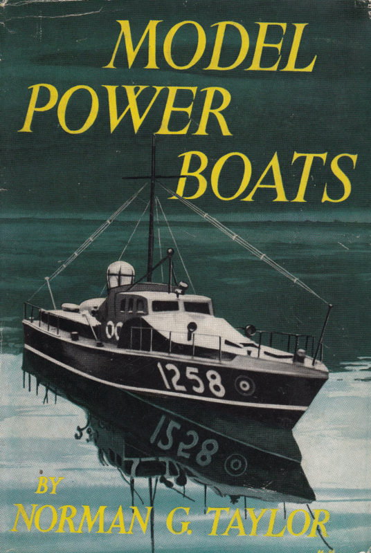
MODEL POWER BOATS
BY THE SAME AUTHOR Mopet AEROPLANES Mopet Moror Boats Mopet Racine Cars Move. Racine YaAcuTs Mopet MaKeER’s WorKSHOP THE Complete Book oF THE MopEL AEROPLANE
.1.—Always popular—a typical 33 -1n. scale model of an Air Sea Rescue Launch bu i It_by Mr. H._ N. Taylor from plans by Norman G. Taylor oe Fi oe
MODEL BOATS POWER by NORMAN G. TAYLOR With 211 illustrations in the text LONDON
CASSELL & CO LTD 37/38 St. Andrew’s Hill, Queen Victoria Street London, E.C.4 : and at 31/34 George IV Bridge, Edinburgh 210 Queen Street, Melbourne 26/30 Clarence Street, Sydney 24 Wyndham Street; Auckland, New Zealand 1068 Broadview Avenue, Toronto 6 P.O. Box 275, Cape Town P.O. Box 1386, Salisbury, S. Rhodesia Munsoor Building, Main Street, Colombo 11 Haroon Chambers, South Napier Road, Karachi 13/14 Ajmeri Gate Extension, New Delhi 1 15 Graham Road, Ballard Estate, Bombay 1 17 Chittaranjan Avenue, Calcutta 13 P.O. Box 959, Accra, Gold Coast Avenida 9 de Julho 1138, Sio0 Paulo Galeria Gittemes, Escritorio 518/520 Florida 165, Buenos Aires 5 rue Henri Barbusse, Paris 5e Islands Brygge 5, Copenhagen – First Published 1956 COPYRIGHT 1956 BY NORMAN G. TAYLOR MADE AND PRINTED IN GREAT BRITAIN (TAYLOR GARNETT EVANS & CO, LTD.) F, 1055 BY GREYCAINES WATFORD, HERTS
PREFACE THE preparation of this book dealing with the art of model power boat construction has given me much pleasure, because my ‘first love’ was model boat building when only a schoolboy, and since those happy days I have always gone back to the hobby whenever my other model-making activities permit. Of all the many and varied branches of model-making, model boat construction must surely be one of the oldest, and certainly one of the most intriguing and romantic. The designing and building of model power boats has much to offer to both young and old, for it combines indoor and outdoor activity in a manner which is both healthy and instructive. The construction of a model indoors when perhaps the weather is unsuitable for anything else, coupled with all the outdoor activity of operating it when completed, makes model boat building the ideal hobby—a hobby which calls for very little initial outlay—a hobby that will fire the imagination of young and old alike and help recapture on a small scale that old adventurous spirit of the sea. Only those who have actually built such a craft can know the fascination of operating a good scale model power boat on the sparkling waters of the local pond or lake. In presenting this book it is my sincere hope that the advice contained herein on constructional methods, power units, design and many other matters, will be the means of recruiting many more enthusiasts to the ever-increasing ranks of model boat builders. I would take this opportunity of gratefully acknowledging my indebtedness, and of extending my cordial thanks, to the following organizations for much help and information, and for their kind permission to reproduce many illustrations which appear in the following pages: The Model Power Boat Association, Messrs. Bassett-Lowke Ltd., Northampton; Model Maker Plans Service, Watford, Herts. ; Norman’s Model Supplies, Wimbledon, S.W.19; Model Aircraft (Bournemouth) Ltd., Bournemouth, Hants.; A. A. Hales Ltd., London, N.11; Taycol Ltd., Bournemouth, Hants.; Electronic Developments (Surrey) Ltd., Kingston-on-Thames; International Model Aircraft Ltd., eee]
PREFACE London, $.W.19; Davies Charlton Ltd., Barnoldswick, Lancs.; Amco Model Engines Ltd., Alperton, Middlesex; The Ever Ready Co. Ltd., New Malden, London, N.7; Venner Accumulators Ltd., Surrey; Chloride Batteries Ltd., Manchester; Wilmot Mansour & Co. Ltd., Totton, Hants.; and The Model Shop, Newcastle-on-Tyne. A book such as this would be impossible without such help and co-operation between friends. WIMBLEDON NORMAN G. TAYLOR be.
CONTENTS PAGE CHAPTER I INTRODUCTION TO THE HoBBy II THEORETICAL CONSIDERATIONS 20 Ill PLANNING AND DESIGN 40 IV Motive PowER—INTERNAL COMBUSTION ENGINES Vv MortitvE . Power — ELecrriciry, STEAM VII VII IX XI AND 86 JETEX VI 63 Hui CoNnsTRUCTION 111 SUPERSTRUCTURES AND Deck FITTINGS 138 PROPELLERS AND TRANSMISSION 167 ‘FITTING Out’ AND FINISHING 7S) CONSTRUCTIONAL Kits 194 RULES AND SPECIFICATIONS 203 GLossARY OF TECHNICAL ‘TERMS All INDEX 222 3 [e4
To my Sons BRIAN AND RICHARD
CHAPTER I INTRODUCTION TO THE HOBBY ANYTHING that works has more than ordinary appeal to the general public, as witness the crowds at any of the important model power boat contests and regattas, or even the vast number of people (both young and old) who gather so rapidly around a model when it appears at the water’s edge! A model power boat combines the fascination of the miniature, with the allure of the thing that ‘goes’—it has life and motion and makes a decided appeal to the eye and ear, especially when it is one of the ultra high-speed spark or without a regulation silencer! glow-ignition boats running Types of Models Working model power hoats, as opposed to any other class of working model boats such as yachts, cutters, etc., may be classified into three basic groups, these being (1) scale models, which should include true to scale replicas and representative models of all types of full-size vessels and also those in which slight modifications have been made below the water-line in order to increase ‘displacement’ and provide sufficient space for fitting the power plant, at the same time maintaining the true ‘full-size’ appearance as much as possible when afloat; (2) semiscale models, in which modifications are made both above and below the waterline in order to simplify construction and to make for increased all-round general efficiency; and (3) the purely functional type of model, i.e. speed-boats, hydroplanes, and other free-lance designs, in which appearance is sacrificed for the utmost speed and efficiency. Figs. 2 and 3 illustrate two typical and excellent scale models on which a great amount of time may be spent in getting every detail and fitting of the full-size prototype correct to scale. Models of this type are usually fitted with an electric or steam power plant. By far the most popular class of model at the present time is the semi-scale, this no doubt being due to the fact that ample power to give models of this type a realistic and interesting Fee
MODEL POWER BOATS Fig. 2.—Scale modelling at its best—a superb exhibition model of the cross-channel ship ‘Falaise’ by Messrs Bassett-Lowke Ltd. performance is now readily available in the form of the small compression-ignition (‘diesel’) engine which, in the past few years, has done so much to popularize the hobby. The models shown in Figs. 4 and 5 are typical of their class, and could easily be two of the many hundreds which may be seen in action on any of the model boating ponds throughout the country on any fine week-end. Model speed-boats and hydroplanes are what one may call ‘functional designs’ and in nearly all cases, especially for speedcontest work, appearances have to be sacrificed for utmost performance, speed, and general handling qualities; although let it be put on record that there are many speed-boats which have both good looks and performance. A model of the hydroplane type is shown in Fig. 6. When watching models of this type performing it will at once be observed how they travel “on the step’ when a certain speed has been reached. On Choosing a Model When first starting model boat building it is of the utmost impoitance to choose the correct type of model for your requirements and one which will also appeal to you. The newcomer to the hobl-y is strongly advised never to be tempted to commence with one of the more complicated types until a little practical experience has been gained by constructing and operating two or three simple models intended for beginners. There are many small hinis and tips which may be learnt in this way by [12]
INTRODUCTION TO THE HOBBY eee ee Fig. 3.—Craftsmen assembling a model of the ‘Norge’ built to the order of Messrs. Camper & Nicholson by Bassett-Lowke Ltd. progressing from the more simple types to start with—such little things as the best method of construction, painting, engine starting (in the case of internal combustion engine powered models), and handling the model in the water. Then, when you are ready, the larger and more complicated models may be tackled with complete confidence. ~ Facilities for operating your model whenit is completed should always be taken into consideration when deciding on the type you are going to build. Itis advisable to make a point of visiting all local ponds or lakes, and to inspect them at first hand to discover which is the most suitable for model boat operation. For the exposed waters of natural ponds or lakes, models of from 30 to 39 in. are usually the most suitable; of course, a smaller model than the size just mentioned may be constructed, but generally speaking, nothing less. than 30 in. is really practical on anything like exposed water. On the other hand, where there is calm unruffled water available, such as may be found in many artificial ponds, which are usually sheltered by their steep banks, the really small type of model (12 to 24 in. in length) may be operated quite successfully. [13]
MODEL POWER BOATS Fig. 4.—Typical semi-scale cabin cruiser for electric motor or ‘75 to 1-5-c.c. diesel engine. Length: 31 in. Beam: 84 in. From the workshops of Norman’s Model Supplies, Wimbledon Storage space and method of transport are usually the two governing factors when deciding on the general size and overall length of your model. It is surprising how much space a large model of, say, about 48 in. or more will occupy in that spare room! Hence the popularity of the 30-in. and ‘Metre’ (39-370-in.) classes, both of which are quite easy to carry and transport. For anything larger than the ‘Metre’ size, the use of a car or a Fig. 5.—‘Lorelei’ designed by Vic Smeed and built from plans supplied by the Model Maker Plans Service. This is a simple cabin cruiser for small diesels or electric propulsion. Length: 34 in. Beam: 7} in. E14]
INTRODUCTION TO THE HOBBY cycle trailer is really necessary for getting the model to the water, unless, of course, you are lucky enough to live very near a suitable pond. If you are constructing a speed-boat or hydroplane, transport difficulties should not -worry you unduly, because this type of model is very rarely more than 39 in. in length. At the outset, success in the building of a model boat depends on just three things: knowing beforehand just what type you want to make, obtaining the right power plant, and then getting started right with the construction. Once you have an accurate full size plan the rest is comparatively easy. Considerable experience of designing and building is necessary Fig. 6.—A typical diesel-powered Hydroplane at speed before one is able successfully to produce working drawings in detail for a model which will be really satisfactory and efficient on the water. For the beginner, by far the easiest and cheapest way of making a first model is to purchase one of the many excellent constructional kits which are now on the market, and to follow exactly the detailed building and operating instructions which are usually included therein. The chances are that your local model dealer is an enthusiast, and he will always be pleased to give practical advice and help in selecting a suitable type of model and power unit. By purchasing a constructional kit you get the advantage of having all the basic materials from which to build the model selected in the correct quantity without having to ‘over buy’ on the many small items which go to the making of a model boat. Another advantage gained by the beginner who starts with a kit is that all small and intricate parts (such as bulkheads, formers, and superstructure parts) are usually clearly printed on wood of the correct type and thickness in readiness for cutting out. Many kits contain all parts [15]
MODEL POWER BOATS pre-cut ready for assembly, all of which is a great help for the beginner and ensures accuracy. Fundamental Requirements For successful operation the model power boat must possess certain well-defined characteristic. These main practical requirements may be listed as follows: (1) The hull must be of sound practical design, and it must be of sufficient size and strength to accommodate the power plant required, with suitable provision for mounting the machinery and the fixing of propeller‘shaft and rudder assembly. (2) A vessel will, when placed on the surface of the water, ‘displace’ an amount of water equivalent to its total weight. Hence it will be seen that small heavy models should be avoided, and that weight should at all times be kept down to reasonable proportions. (3) A model should be fitted with a power plant capable of giving it a realistic and also reliable performance. Choosing the correct type of motive power is a matter of great importance, and is discussed in detail in following chapters. (4) An accessible switch for starting the electric motor at time of release must be provided, or, in the case of models employing other forms of propulsion, good accessibility to the power plant for starting, refuelling, etc., this usually being achieved by having a portion of the superstructure detachable with a quick and. ezsy ‘snap on’ method of fastening. (5) General finish and appearance are two items which should not be overlooked. When afloat, the model when seen from a distance of 10 to 30 ft. from the shore should look like the real thing. Even at this short distance all the small details are lost to view, and it is because of this that the utmost care should be taken suitably to. proportion and dispose the masses, i.e., superstructure, funnels, deck-houses, masts, etc. By so doing it is surprising what a semblance of reality and scale appearance is obtained without bothering too much about the smaller details and fittings. The most important feature of any scale model boat should be fidelity; it should convey to the beholder a sense of the magnificent appearance of the original, both when in dock and when cruising across the water. Minute detail should be studiously avoided, as it has a tendency to make a small model look clumsy and out of scale—this does not apply to large scale models of small size prototypes. tie)
INTRODUCTION TO THE HOBBY Fig. 7.—Models such as this fine cross-channel ship are ideal for electric or steam propulsion. Note how only essential details of superstructure and deck fittings give neat appearance Effect of Scale on Size One effect of building a model to a fixed length is that the scale of the boat varies according to the length of the prototype. Thus a ‘metre’ model of a 600-ft. liner would have a scale of 40/7200 or be 1/180 full size; in other words, 15 ft. equals 1 in. If, however, a river launch or some other boat of, say, 60 ft. in length were taken as prototype the model would be to a scale of 1/18 full size, or 14 ft. equals 1 in. Thus the size of all the deck fittings varies considerably on models of fixed length but representing different prototypes. Consequently the designer and builder of any mcdel should first determine the length of the model, or the scale; and arrange. everything accordingly. Practical Utility of Models Lest anyone should think that model boats are merely toys, it may be well to mention that hundreds of thousands of pounds are expended annually on scientific experiments and tests with models of intended ships. In fact, the basis of naval architecture is practical experiment with ship models, and the knowledge so gained has done very much to perfect the modern ship. Useful Tools An elaborately equipped workshop is certainly not essential for the construction of a model, except perhaps for the most B | Wy]
MODEL POWER BOATS advanced exhibition types, some very fine examples of which may be seen in the Science Museum, South Kensington, London, and in the offices of nearly all large shipping companies. But very few tools are necessary for building the more simple working types—in fact, many excellent models which are built are in the ‘kitchen table’ class. Modern methods of construction and the increased use of balsa wood and plywood have done much in reducing time, skill, and tools required to build an average working model. Surprisingly few people realize how suitable balsa wood is, and to what extent it can be used, in model shipbuilding. It is easy to cut and handle, the medium grades being suitable for formers, bulkheads, etc., while the harder and heavier variety with its very high strength/weight ratio may be used to great advantage for planking hulls and the construction of deck-houses, superstructures, etc. Of course, it is obvious that the facilities of a small workshop are an advantage, but many of us lack the necessary space for fitting out a special room just for building models. With this in mind, it is suggested that the following may be found to be the most useful tools for the beginner to obtain, these being listed in order of importance: 1, First and most important is a workbench, strong table, or building board (which really serves as a portable workbench) on which all the actual construction will be done. A draughtsman’s drawing-board makes an ideal building board, and is_ generally made of pine, a soft wood which is not liable to warp, and into which pins can be easily knocked without bending. For a small model of anything up to 30 in. in length, a piece of good-quality timber approximately 32 in. by 9 in. and 1 in. thick will serve quite well as a building board, providing always that you choose a length that is absolutely straight and free from knots. Remember that small pieces of unpainted wood show up better against a dark background, so it is a good idea to water-stain your building board a dark shade of brown to facilitate working with very small parts. 2. High up on our list of essentials must come a means of cutting the timber which will form such a large proportion of the completed model. Most of the wood used is obtainable ready cut in the small sections required, therefore our saws need only be quite small. The most useful would be a brass-backed modelmaker’s tenon saw, a fretsaw frame with an assortment of fine, medium and coarse blades, and a small coping saw. [ 18 ]
INTRODUCTION TO THE HOBBY 3. Next follows a group of three inexpensive basic tools. These are normally to be found in most households: (a) Small hammer. (6) Pair of small pliers. (c) Small and medium screwdrivers. 4, A 12-in. steel rule is always useful, not only for measuring, but also for use as a straight-edge when cutting paper, thin ply, and thin sheet balsa wood. 5. Hand brace and set of twist drills (J;-in. to }-in. diam.). 6. Small wood rasp and spokeshave. 7. Selection of chisels and gouges. 8. Pair of good-quality heavy-duty wire cutters. _ 9. Carpenter’s and metal-worker’s set squares. 10. Sharp knife for carving stem and stern pieces, etc. 11. Half-dozen woodworker’s cramps (small). 12. 4-,4-, and 2-in. flat and half-round files. 13. Sandpaper,Pers des 0, 1 and 2. Suitable sanding block. 14, Two or three dozen brass drawing pins. 15. Packet or box of onary household pins (steel). 16. Assorted panel pins (4-, 3-, and 4-in.). 17. Assorted wood screws ($-, 3-,$-, ou 2-in.). Nearly all the above mentioned tools are een for building various types of models of up to medium size. Individual requirements vary to such an extent that it is quite impossible to lay down any hard and fast rules concerning the selection of tools. The enthusiast will soon want to make further additions to his equipment; other useful acquisitions are a good strong vice, an electric soldering iron and equipment, and a treadle or power operated fretwork machine which will save a lot of time and hard work when cutting out both large and small -3-ply and other hardwood parts. For further detailed information regarding the selection fad use of tools, the reader is réferred to Cassell’s Model Maker’s Workshop in the “(New Model Maker Series’’, price 4/6d. [ 19]
CHAPTER II THEORETICAL CONSIDERATIONS PrAcTICAL modellers are sometimes disposed to scoff at the mere word ‘theory’ and deny its usefulness; others adhere slavishly to the idea that by calculation, formula and algebraic conjuring it is possible to evolve a stupendous success. Both are wrong, because the theoretician and the practical exponent can each learn something from the peculiar knowledge of the other; therefore, the ideal must surely be to combine a reasonable amount of theory with the results of practical experience in all models designed and built. Aim of the Theoretician The theory-man accumulated merely experiences endeavours of the past, to and co-ordinate by the analogy, by accurate deduction and by inference, to look forward into the future. Further than this, theory can and does enable the practical man to attain his ends or produce a better result with the minimum of labour. After all, there must be a reason for every happening, and so-called theory aims at giving reasons and stating laws which govern them. Furthermore, it attempts, with no small degree of success, to enable the naval model architect to design a model boat to fulfil stated conditions. Primary Considerations The student of naval model architecture finds that there are manifold difficulties to be overcome in the design of a successful model power boat. Stability indicates the need for a broad boat and the correct placing of the ‘metacentre’, the demand for speed necessitates fine lines, while other requirements such as radio control and steering qualities may well introduce fresh factors. To overcome all difficulties and produce an harmonious design is the aim of all naval architects. This chapter is intended as far as possible to show how and why the utilized. differing factors in a [ 20 ] boat design can best be
THEORETICAL CONSIDERATIONS Why a Boat Floats Primary attention must be given to grasping the fundamental principle of buoyancy, or the power a ship possesses of floating in water, while at the same time maintaining proper trim and stability. At first glance it seems impossible that a model constructed of metal should float. That a boat can do so is due to ‘displacement’ or ‘buoyancy’—that is to say, when a boat is floating in water it displaces or pushes away a volume of water equal in weight to the otal weight of the model. Displacement of Water For example, if a bowl of water full to the brim contains six pounds weight of water, and into this a rectangular block TOTAL WEIGHT IO Ib. [| TERED LE Ze 2210 cub inODE Fig. ae and displacement diagram of wood weighing exactly one pound is introduced, it is obvious that a certain quantity of water will overflow. If the wood is removed and the amount of water remaining in the bowl is again weighed it will be found that it now weighs exactly five pounds, thus showing that one pound weight of water has been displaced. Volume of Displacement The first thing when designing a model power boat is to ensure that the volume of that part of the vessel to be immersed in the water shall displace a weight of water exactly equal to the total weight of the boat. This principle is the most vital of the many involved when designing a model boat. For a boat to be able to float, its immersed volume, i.e. the part of the hull that sinks into the water, must displace a volume of water equal in weight to the total weight of the boat. A model that weighs 10 lb. for example, must displace 270 cub. in. and [ 21 ]
MODEL POWER BOATS leave some portion of the hull above water; because 27 cub. in. of fresh water weighs 1 Ib. Fig. 8 represents a model boat hull weighing 10 Ib. floating in water. The immersed portion of the hull displaces 270 cub. in. of water—in other words the volume of displacement is 270 cub. in. The weight of this quantity of water being 10 Ib. the boat is able to float. Note that the volume of displacement of the boat is due to that part which is immersed, or in the water. The total volume of the hull is greater than 270 cub. in. because there must be sufficient ‘freeboard’ or above-water portions of the hull on which to erect the superstructures. Correct Flotation It is not sufficient for a vessel to float but it must float in an upright position, and not be unduly liable to capsize; in other words, the vessel must possess stability. Stability may be defined as the property a vessel possesses of returning to the upright position after having been slightly inclined from it. Conditions of Equilibrium Having grasped the fundamental facts of displacement, it is necessary to consider the manner in which the volume of the immersed portion of the hull has to be arranged to ensure the boat floating at a pre-determined level. The placid state of flotation is known as equilibrium and the three primary conditions of equilibrium of a floating body are: (a) The weight of the body must equal. the weight of the water displaced. (6) The centre of gravity and centre of buoyancy must be in the same vertical line. For a vessel to float in the desired upright position the third condition is essential: (c) The metacentric height must be positive. Fundamentals of Stability A body possessed of bulk and mass has weight, and located somewhere in that body there is a centre upon which it could be balanced, were it accessible. The balancing point is called the centre of gravity. The [ 22 ]
THEORETICAL CONSIDERATIONS force of gravity always acts vertically downwards through that centre, no matter how much the position of the body may be changed in respect to a plane of reference, such as the surface of water. The centre of gravity is usually referred to on plans and diagrams by the letters C.G.; and the position of this centre never alters in a boat unless some of the weights in it are moved. Buoyancy A body when floating in water possesses another property known as buoyancy, which is virtually the reaction due to gravity. The immersed surfaces of a model boat hull floating at rest in water may be considered as experiencing pressures . perpendicular to them, and the sum of these pressures must equal the weight of the vessel. The centre of buoyancy is the centre of gravity of the immersed volume of the hull, and is that point at which the buoyancy pressures are concentrated. When the model is upright, the centre of buoyancy is in the longitudinal middle line, but when inclined or heeled, the centre of buoyancy moves to some new position dependent upon the immersed form of the hull. Transverse Stability The power to resist heeling, or an inclining force tending to tilt the hull sideways, is known as transverse stability and is chiefly conditioned by the form of the hull, the height of the metacentre, the ratio of depth to beam, and the relative heights of the centre of gravity and centre of buoyancy. At this stage of the investigation of a model boat hull floating upright and at rest in water, the following conditions or properties are known, and their magnitude can be ascertained by calculation: (a) The weight and volume of water displaced. (b) The C.G. is on the longitudinal central plane of the hull. (c) The centre of buoyancy (C.B.) is vertically beneath the C.G. This knowledge can be usefully employed in several ways; for example, when the total weight of an intended model is known, the appropriate volume of displacement can be ascerng weight in Ib. by 27. Obviously, theretained by multiplyithe contrive an immersed hull form which must designer fore, the will have exactly that number of cubic inches of volume. [ 23 ]
MODEL POWER BOATS Determining Permissible Weight Conversely, if the hull is designed first, the volume of displacement can be ascertained, and this divided by 27 will give the total permissible weight of the boat Fig. 9.—Centre of Buoyancy and Gravity pee CoP Poe accessories. gl Provided the conditions of equilibrium are complied with, such a hull will float at rest and upright; but it is most important to determine its stability, which can only be done after further investigation, Conditions of Transverse Stability These can best be studied by means of some simple diagrams . The first, Fig. 9, represents a cross-section of a model boat floating in water in a normal upright position. at The centre of gravity is shown at C.G., the centre of buoyanc y C.B.; the forces acting through them are in equal and opposite directions. Now if a horizontal force applied to the vessel causes it to incline to the right and assume a position shown in Fig. 10, the centre of gravity of the hull will be unchanged, and still remain at the same spot, C.G., on the centre- line of the boat; but the centre of buoyancy will move over to the right. There are three forces acting on the hull, one due to gravity or the weight of the vessel acting downwar ds through the C.G.; the second force also equal to the weight of the vessel, acting upwards through the centre of buoyancy and due to the flotational powers of the vessel. The third force is that which causes and maintains the change of position, and may at present be disregarded. Righting Couples Two equal, opposite, and parallel forces are termed a couple, and when they act together to maintain a stable condition of the hull they are ee known as a righting couple. Fig. 10.—Forces acting on Hull when inclined [ 24 ]
THEORETICAL CONSIDERATIONS _is the product of either force The moment of the couple into the perpendicular dis- tance between them. Thus the length G—Z ~< \ : y (used to distance) CGe multiplied by the weight of Cpe designate this the boat, is equal to the a moment of ‘statical stabil- = ity’. The length G—Z is also known as the stability lever. By inspection of Fig. 10 < . ‘ Fig. 11.—Neutral Equilibrium it will be observed that the centre of buoyancy acting upwards and to the right of the centre of gravity, through the agency of G—Z (the stability lever) exerts a righting force on the hull, causing it to resume the upright position; in other words the vessel is stable. Upsetting Couples If the hull were inclined to a much greater angle, as indicated in Fig. 11, until the centre of gravity and centre of buoyancy coincide in the same vertical plane, the vessel would remain in this position, the righting moment having reached zero. Should the vessel be heeled still further, the centre of buoyancy will travel to the left of the centre of gravity, and by augmenting the heeling force will cause the vessel to capsize. Such a couple is known as an upsetting couple. The Metacentre The word ‘metacentre’ is applied to the point where the vertical line of action through C.B. when the boat M is inclined cuts the original vertical central the boat. plane of This point—denominated M—is a fixed point for all small angles of inclina- tion, say up to 15 degrees or thereabouts. The relative positions of C.G. and M determine Fig. 12.—Method of finding position the stability of the model. of Metacentre When M [ 25 ] is above G, as in
MODEL POWER BOATS Fig. 12, the vessel is in a stable condition. When M and G coincide, that is to say, when the metacentric height is nil, the vessel is in equilibrium. When M is below G, the vessel will be in unstable equilibrium, and will capsize. Metacentric Height The height of the metacentre depends upon the immersed form of the vessel, and is quite independent of the length of the ship. The height is most conveniently ascertained from a drawing similar to Fig. 12, showing the vertical line through the centre of buoyancy, and extending it to cut the inclined line representing the original vertical central fore and aft plane of the ship. The distance between C.G. and M is known as GM and is equal to the moment of inertia of water plane area about the middle line, divided by the volume of displacement; and is strictly proportional to the of the breadth, and inversely proportional to the square depth. Metacentric Moment of Stability For all angles of inclination up to about 15 degrees or so the righting lever is equal to the height GM multiplied by the sine of the angle of inclination from the vertical. The moment of the restoring couple is equal to W x GMsine O, is displacement; where W GM is height of metacentre above C.G.; O is angle of inclination. For moderate angles of inclination the moment of stability is obtained by the above formula. Hence the conditions of sideways rolling of a model boat are governed by the height of the metacentre. Metacentric heights in real practice are approximately 20 ft. for a shallow draft flat-bottomed boat; about 5 ft. on a battleship; 3 ft. on light cruisers; about 24 ft. on tug boats; 14 to 2 ft. on T.B.D.s; from 6 in. to 2 ft. on passenger boats and liners. These heights reduced to appropriate scale will be useful A high metacentre makes a as a check on model boat designs. boat stiff or jerky in action, a medium or small metacentric height produces a boat with a low period of oscillation, that is, a boat that has a long, slow roll. [ 26 ]
THEORETICAL CONSIDERATIONS Effect of Ballast The addition of ballast, or a weight low down in the hull, alters the designed metacentric height and consequently affects the transverse stability. In general it tends to make the boat stiff and roll badly. The important point to grasp is that stability depends fundamentally upon the distance between C.B. and C.G. and the distance GM when the boat is inclined; and further, that the action of the boat amongst waves is markedly affected by the metacentric height and by the length of the stability lever. Hence the addition of ballast to introduce others of. worse character. correct one fault may Form of Immersed Hull The best design for a given purpose is that which has the most appropriate under-water hull form. When the boat is heeled the shape of that part which is in the water is different— in respect to the water—from what it was when upright. This new form determines the whereabouts of the C.B. in the heeled position and thus affects the stability and action of the boat. Action of Boat amongst Waves When a model power boat is travelling through a series of waves, so that, for example, one side of the hull is supported by the crest of a wave and the other side rests in the trough, a heeling force is imparted to the hull, and momentum carries it farther in the same direction until all these forces are balanced. As the boat passes out of the wave the forces diminish and the boat comes back to a normal plane of flotation. When the wave system is continuous at regular intervals, a rhythmic series of oscillations is set up and the boat continues rolling. The duration and periodicity of such rolling can be determined, or predicted, by rather intricate calculation; the model boat designer is therefore advised to confine attention to the general results obtainable from characteristic hull forms and changes in the length of the stability lever. Longitudinal Stability The longitudinal stability of a vessel is the power it possesses of resisting changes of trim, that is, variations of level in fore and aft direction. Actually, the same laws apply as those governing transverse [ 27 ]
MODEL POWER BOATS stability, but they are customarily dealt with separately. In one respect the problem is not so pressing because it takes a much greater force to affect the longitudinal stability. Disposition of Hull Weights Practically it becomes a matter of correct disposition of the weights in the hull when trimming a model for maximum longitudinal stability, as their position determines the fore and aft position of the C.G. and this must in any case be in the same vertical line as the C.B. But as the position of the C.B. is determined irrevocably by the shape of the immersed portion of the hull, it follows that the weights in the hull must be moved backwards or forwards until C.G. is in the vertical plane of C.B. The correct placing of the weights in the model calls for extreme care, as it should be apparent that when the position of C.G, alters, tlie boat must change trim until the immersed portion of hull, forwards or aft of the normal centre of buoyancy, displaces a sufficient amount of water to restore equilibrium. This shows the necessity for correct placing of weights, and proper proportioning of the forward and after bodies, as the portions of the hull ahead of, and astern of, the midship section or centre of gravity are termed. Reserve of Buoyancy To retard ‘pitching’, or sinking by the head, a good flare is needed at the bows, and as far as possible, a reserve of buoyancy aft to counteract the evil of ‘squatting’, or sinking at the stern. Beam to Length Ratio The proportion of beam to length of hull is known as the beam/length ratio; and this in conjunction with the beam to depth ratio has a marked effect on stability, speed, and the action of the boat amongst waves. A narrow boat with a fairly deep body is usually unstable; a broad, shallow boat, is very stable until considerably heeled. Various general types of hull have gradually evolved as the best for specified purposes: broad shallow hulls for racing; a rounded body for an easy seaboat; a rectangular section for maximum carrying capacity, and so forth. The ‘sharpie’ or box form hull has the maximum initial stability, and a circular section possesses a very low stability in a sea way; hence to reconcile compromise is often necessary. [ 28 ] these differing factors a
THEORETICAL CONSIDERATIONS The foregoing remarks apply particularly to boats of normal form, or those generally called displacement-boats; the conditions governing the action of hydroplanes, or small craft adapted to skim over the surface of the water, are in a somewhat different category. Brief consideration will show that there must be a critical speed beyond which it is impossible to drive a displacement type of boat through the water, because it will clearly take a definite time for the water to be pushed aside to allow the hull to pass, and a corresponding time for the water to flow back again. When a displacement type of boat is driven at higher speeds the hull is forced out of the water at the bows or stern and will ultimately sink outright. Hydroplanes A hydroplane is a boat intended to rise bodily at its critical speed, until it is partly out of the water; this obviously reduces skinfriction and therefore allows much higher speeds to be attained. Two separate states or conditions require to be considered; first the ordinary laws governing displacement boats, such as the displacement, initial stability and so forth, which must be adequate when the boat is at rest and apply until the critical speed is reached. At and beyond that speed the boat exhibits a new property, which for convenience may be termed dynamic stability. The phenomenon of dynamic stability is exemplified by an ordinary bicycle. This, when at rest, will not remain unaided in a vertical position, but when set in motion it acquires the property of stability, and safely and vertically supports the rider. Dynamic stability is imparted to a model hydroplane by reason of the form of the hull and the relative solidity of the water at high speeds. A graphic understanding of the forces acting on the usual double flat plane type of hull can be appreciated from the diagram Fig. 13, which shows in profile a typical hydroplane hull. Balance of Opposing Forces Suppose the fore and aft position of the centre of gravity is located at G., and the centres of pressure on the two inclined surfaces are located at A and B; it follows that the pressure on the forward plane will exert a turning effort about G., and the pressure upon the after plane will act similarly but in the contrary direction, [ 29 ]
MODEL POWER BOATS Complete dynamic stability is only obtained when these forces acting through A and B exactly balance one another, as under that condition the hull will then tend to rise bodily and will moreover be remarkably steady when running at high speed on smooth water. as =e — Fig. 13.—Forces acting on a Hydroplane Hull RESISTANCE AND PROPULSION The word resistance is applied in a general sense to the sum © of all the forces acting upon a model boat which retard or entirely prevent its passage through water. These resistances are due to several separate and distinct causes, and so far as they apply to displacement boats can be subdivided into five groups, which in order of importance are called skin friction, eddy making, wave making, the wake, and air resistance. Skin Friction The frictional or skin resistance is caused by the friction of the water on the immersed surface of the ship. The laws governing it have been enunciated by the researches of the late Dr. W. Froude, who found that the resistance varies with the nature and the length of the surface in the direction of its motion; and approximately as the square of the speed. The experiments enabled the skin friction to be accurately determined, and for all practical purposes the resistance per square foot of wetted surface taken as a mean over the whole surface of the hull can be fixed at the following values: Varnish Paraffin Wax -Tinfoil ah a a as — “41 Ib. “38 s ue 30 4, ,, Coarse Sand .. = se 110; These results were obtained at a speed of 10 ft. per sec., which equals 5-92 knots, or 6-8 m.p.h. [ 30 ]
THEORETICAL CONSIDERATIONS Average Resistance of Model The approximate resistance of a model power boat is about +25 Ib. per sq. ft. of wetted surface at a speed of 6 m.p.h., and ina metre model of average form would be in the neighbourhood of 4 lb., assuming a surface of 280 sq. in. immersed, at a speed of approximately 7 m.p.h. It should be noted that the resistance varies considerably according to the nature of the surface; hence the practical ship modeller will endeavour to secure a perfectly smooth hull surface. Increased Resistance at Speed The foregoing figures for skin friction were taken at a speed of 5-92 knots, but the resistance varies with changes of speed. Skin friction varies as the 1-83 power of the speed. The calculations are intricate, consequently the following table of values (Prof. Sir H. J. Biles) should be of help to the designer. FRICTIONAL INDIE EL, : RESISTANCES V=Speed in knots IM [es (<5 ) We \ 1-83 oe 1-15, 1 0386 3°45 OPS 3 3 2883 7341 7 1-359 10:3 8-06 5 Dell sy 12-6 11 3-107 es 13 GePNG) 17-27 1S 5-482 1955 17 6-893 268 19 8-448 24-1 29:33 21 22 11-048 26-4 25. 11-985 28-78 25 13-961 31-09 27, 16-071 34-5 30 19-489 38-0 33 wes 35 232202 25-841 42-60 37 28-606 46-04 40 322993 [ 31 ] 10-146
MODEL POWER BOATS The formula for the calculation of frictional resistance due to skin friction is: RF=FMxMxs RF=Frictional resistance in pounds. FM=Mean resistance in pounds per sq. ft. of wetted surface. V = (sz) \1-83 S=Surface of immersed hull in sq. ft. The table is used in the following way: Suppose, for example, that FM equals -41 lb. per sq. ft., and the model has 24 sq. ft. of wetted surface, then FM equals 1-025 lb. at 6-8 m.p.h. To find the resistance at any other speed (either in knots for example, 25 m.p.h.; under column V or m.p.h.), say, equals speed in m.p.h. opposite 25-33 read 11-048 as the value of M. Substituting values in the formula; RF equals 1-025 x 11-048 ==11103)2 ily. This enormous increase of resistance with increase of speed is one of the chief reasons why so much more power is needed materially to increase the speed of a given model boat. It should also be remembered that skin friction imparts a velocity to the water in the immediate vicinity of the hull and partly causes the zone of frictional disturbance and the frictional wake, and to some extent distorts the stream lines, or energy flow, around the hull. Eddy Making Eddies are disturbances of the water caused by partial aeration and internal movement of the water. Eddy making caused by appendages such as shaft brackets, rudders and sudden changes of hull form is not a serious energy loss, except at high speed when it becomes imperative to take all possible steps to eliminate eddies. The practical remedyis elimination of all such changes of hull form and a careful streamlining of those which cannot be dispensed with. Wave Making Lord Kelvin defined wave making as an “orderly progression through matter of a state of motion,” and as “‘the progression of a displacement.” [ 32 ]
THEORETICAL CONSIDERATIONS oe . Fig. 14.—A selection of ‘Solid’ Glass Case models built by Norman G. Taylor to a scale of 100 ft-1 in. Reading from the top these are: ‘Britannic’, ‘Strathnaver’, H.M.S. ‘Repulse’, H.M.S. ‘Hood’, ‘Queen Mary’ and ‘Normandie’. These models are fascinating to construct, and make excellent ornaments for studio or ‘den’ Cc E33]
MODEL POWER BOATS When a model boat is at rest the hull surfaces are, practically speaking, subjected to uniform hydraulic pressure. When the boat is set in forward motion, the distribution of these forces is disturbed, and this change is accompanied by a corresponding. alteration or increase of pressure in one part, with a diminution of pressure in others. The surface pressure due to the weight (Hire | —— ——= —_—— Cc | =e cost = —_ = | = — .B — eer! — ———d ee Fig. 15.—Wave Making Systems of the atmosphere always remains constant, consequently differences in level become apparent and these differences of level are known as waves. Bow Wave System As the boat moves forward, the normal stream lines at the bows are disturbed and a system of ‘bow waves’ as at B in Fig. 15 is generated. At the stern a similar disturbance takes place, the decreasing speed of the stream lines being accompanied by an increase of pressure, and the formation of a stern wave system as at S. The bow system is caused by the passage of the body and is a regular wave of translation; the energy needed to generate it is entirely lost. Parallel Middle Body The middle portion of a boat is usually more or less parallel and causes little or no extra wave making resistance; the only practical resistance of the middle body at ordinary speeds is due to skin friction. The increased efficiency of large vessels over properly proportioned smaller models measure explained. [ 34] is thus in some
THEORETICAL CONSIDERATIONS Stern Wave System The conditions around the after body and stern of a model boat when in motion are largely conjectural, but in addition to the diverging stern wave system S it is fairly certain that a series of transverse waves as at ‘I are generated which appear to follow the ship, together with the wake, as at W in Bigs 15, Some of the transverse wave system T is due to the frictional disturbance, and some of the energy in it may be returned, as may some of that from the diverging stern wave system. Wave making is a necessary evil and cannot be entirely eliminated, although much can be done in this direction by a clever hull designer. At low speeds of 1$ to 2 m.p.h. wave making is practically non-existent, except with very small models. Wave Making by Hydroplanes The wave systems associated with hydroplanes and boats with ‘steps’ are of various forms, dependant chiefly on the hull form. A characteristic form at the critical speed is sketched in oe if aaeeeaes Ss 1 ee Pp ee —— Se —— eee fis eS ESS ae, e—= ———— Se T — ae 1 ee ' WwW ' ————— 4 —- a ——d«sP=— ee — Seen eee, Som an | ZA i) Gees + B — —— oe =< og — E ee ae Seria Ss —— ——— a — Fig. 16.—Wave Making by Hydroplane at Critical Speed Fig. 16. Usually there is a small bow wave system as at B, a narrower stern system S, and a closely associated duplex system E—P generated by the step. In a well-designed boat this duplex system may be eliminated —or practically so—by arranging that one damps out the other; the result is then a particularly efficient and clean-running boat. [ 35]
MODEL POWER BOATS The Wake The resistance of the wake is due to the water being set in motion in a forward direction, thus resulting in a loss of energy and speed. Some: of it may be regained by suitable propeller arrangement. Air Resistance Many model boat designers pay very little attention to the losses due to air resistance, although a relatively large portion of a model power boat hull is exposed to air currents. Air resistance is only -005 AV (A equals area exposed in square feet; V equals speed in feet per minute), but it increases as the square of the speed, and at the high velocities now attained by model boats becomes a factor that should be reckoned with very seriously. The effect of a head wind is enormous. A model moving at 6 m.p.h. in a calm, with an air resistance of only :540 Ib., experiences an air resistance of 1:5 Ib., against a head wind of only 4 m.p.h. The only practical remedy for reducing air resistance is good aerodynamic design of all cabins, superstructures, etc., and of course good hull design. Total Resistance The sum of the foregoing resistances constitutes the total resistance to the motion of a boat through water; or more properly to a boat that floats on the water; the case of a submarine when submerged is quite a different matter. One of the greatest problems is to ascertain accurately the value of the total resistance at the required speed, as without such knowledge it is impracticable to determine with precision the power that must be developed at the propeller to overcome drag. Power Needed to Drive a Model The energy that must be expended in overcoming the total resistance of a model power boat at a given speed cannot be calculated with absolute precision; all that can be definitely stated is that. the thrust of the propeller must equal the total drag, or resistance. The practical difficulty of ascertaining the necessary power of the engine(s) is due in part to difficulties of propeller design. [ 36 ]
THEORETICAL CONSIDERATIONS A very close approximation, however, can be arrived at for boats of normal form and reasonable speed, by application of the following formula: TH eo FMxV s0000 ~ where T is effective power at propeller, FM is total skin friction in Ib. at the appropriate speed, V is speed of the boat in ft. per minute. Take as an example a metre boat with 2% sq. ft. of wetted surface, then FM will equal 1-02 x 6-89 at a speed of 20 m.p.h., equal to 1,773 ft. per minute. Substituting values in the formula: oy 1:02 x 6:89 x 1773 33000 12460-28 ely eee oe This figure is the power required at the propeller, and to ascertain the total power of the power unit an amount must be added to compensate the losses in engine and propeller shaft friction and any other mechanical losses. Transmission Losses This amount may vary from 25 per cent to 70 or 80 per cent according to the efficiency of the plant. A reasonable average is 40 per cent, consequently from the foregoing example the total power is: 40 x -307 100 = 1924-307, giving a total of -429 h.p. Taking another case, that of a high speed single step flatbottomed boat, running at 42 m.p.h. The skin friction at this speed will be greatly reduced owing to the small area immersed. Taking this at 2/3 sq. ft. gives, from the table on page 31, a value of 16 Ib. at 42 m.p.h. Substituting values in the formula gives: 16 x 3600 33000 = 12 hp. at the propeller. Theory of Propulsion There are various ways of driving a model power boat through the water, of which three are commonly used; these [ 37]
MODEL POWER BOATS are the jet system, the use of revolving wheels with plates or ‘floats’ upon them, and by means of a rotating device known as a propeller or water-screw. The Jet System This method is employed to a limited extent on real boats, and is extensively used in a modified form on many small commercially made models. Essentially it consists in forcing a jet or stream of water in a sternwards direction; the reaction of the moving column of water drives the model forward. (This method of propulsion is in no way connected with ‘Jetex’ jet motor propulsion). Paddle Wheels By the paddle system, a pair of comparatively large diameter wheels are mounted on a shaft directly driven by the engine(s), and placed athwart-ship at about the middle of the length of the boat. Floats or vanes are attached radially to the wheels; the whole is so arranged that only the lower parts of the wheels are submerged, and the floats thereon move through the water in a contrary direction to that of the boat. Forward motion is attained partly by the direct pressure of the floats upon the water and partly because the water is set in motion in a sternwards direction. Originally, it was supposed that the paddle-wheel acted in the water in a similar manner to a pinion in a rack. Actually, however, it is the setting in motion of a column of water which is forced through the adjacent and relatively still water, that drives the boat forward. In some cases a single wide wheel is placed at the stern, but the principle is the same in either case. The Screw Propeller Marine screw propellers are divisible into three groups: (a) those which rotate in air and can be termed air-screws ; (b) those which rotate partly in the water and partly in air, and generally called vane wheels; (c) the totally submerged water-screw or propeller. The first two groups are not extensively used for model ship propulsion, although in certain circumstances they have sundry practical advantages. Except where stated to the contrary the [ 38 ]
THEORETICAL CONSIDERATIONS term propeller is here taken as applying to the fully submerged screw propeller, now almost agrcrsaly employed for marine propulsion. Fundamentals of Propulsion The action of any form of marine propeller—while the boat is in steady motion—is fundamentally dependent upon the sternward projection of a column of water called the propeller race. The change of momentum of this water, per unit time, is equal to the thrust of the propeller, and is balanced by the resistance of the boat. The basic problem of propeller design is therefore to devise _ an instrument which will force a sufficient quantity of water in a sternwards direction, and at a sufficient speed, to equal the resistance of the boat at the given speed. So far the submerged propeller has produced the most satisfactory results. [ 39 ]
CHARTER ITt PLANNING AND DESIGN Ir is essential to have a clear and accurate plan to work to when constructing a model. If you are designing your own boat it is obviously fairly important to have the necessary equipment with which to create the plan; this equipment need not be elaborate, suprisingly few drawing instruments being required for making a full size pencil (or ink) drawing of your proposed model. The majority of model boat builders only require a plan which is full size and accurate enough to work to, and which may be kept for future reference—the elaborate ink drawings on tracing linen for reproduction purposes being left to the professionals! Drawing out the plan for a model is quite easy providing you take a reasonable amount of care, and it is well to remember that should you wish to improve your knowledge of draughtsmanship, the local library will usually be able to provide a number of useful and instructive text books on drawing office practice; by reading these you will soon get acquainted with the fundamental requirements of accurate drawing, the laying-out of plans, and the correct use of drawing instruments. The Drawing Board First and foremost must come the all-important question of the surface on which you are going to draw. A good quality drawing board measuring, say, 42 in. x 29 in. may cost quite a considerable amount of money, but if you can afford to purchase one you are strongly advised to do so. A point worth remembering when purchasing a drawing board is to see that it has a number of slots at the back so that any further shrinkage of the wood will not cause the board to crack on its working surface (see Fig. 17). All good quality boards are made with this feature incorporated. There are, of course, alternatives to a drawing board. In many cases a piece of perfectly flat 3- or 4-in. plywood about 42 in. x 24 in. will do almost as well. If a board of this type is used it is important that the left-hand edge be made perfectly | 40 J
PLANNING straight and true, so AND DESIGN that a tee-square may be used with accuracy. On the other hand, if a flat-topped table is available then this will do quite well for drawing on—a few sheets of paper spread over a table with recesses in its upper surface will prevent the pencil digging through the drawing paper—but in any case the left hand edge should be checked for straightness, and if found to be uneven a strip of perfectly straight timber should be screwed in position (the screw heads being countersunk) - to give an accurate bearing for the tee-square stock to run on. Fig. 17.—Rear surface of good-quality Drawing-Board. prevent workings surface from cracking Slots Drawing Board Sizes Half Imperial .. Be 0 223 1M. Imperial a 2 - 32m. X23 in, .. hous Double Elephant .. Be 2 42m 29m: ANOINTING os i Of Ii. O21: Extra Antiquarian SS -, 60 in. x 36an. Hamburg = 5 . (52 wn, 22 ie, = Drawing Instruments It is surprising how important a straight line designing and laying-out the plan of a model! is when Implements which allow the drawing and positioning of straight lines are: (1) Tee square—Usually made of pear wood with a teak or composition inset bevelled edge. 36 in. is a useful length for the model boat designer. Lat
MODEL (2) (3) POWER BOATS Rule or Straight Edge—Hardwood for drawing, or steel engineer’s type which can be used for drawing and also cutting cardboard, thin ply-wood, etc. 12 in. is sufficient for most purposes. Set squares—A 12-in. 45-degree and a 12-in. 60-degree set square will be of real value. All the above-mentioned items are illustrated in ie; lice reference to which will show how horizontal lines parallel to each other are drawn with the tee-square, and how vertical lines are made by using a set-square in conjunction with the tee-square. Fig. 18.—Tee square, rule, and set square on the Drawing Board Quality before quantity should always come first when purchasing drawing instruments. The essentials are shown in Fig. 19, and consist of the following items: 1. Plain compasses; 2. Plain dividers; 3. Spring-bow compasses; 4. Spring-bow dividers; 5. Protractor (for measuring angles). Inking-in attachments for these instruments are shown, but these will not be required unless reproduction drawings are to be undertaken. Special Drawing Instruments Items not usually found in the mechanical draughtsman’s kit are a set of ‘ship’s curves,’ which are pieces of thin pearwood cut to curved shapes based on the parabola and found by long experience to be generally useful; also a set of ‘French curves’ E42|
PLANNING AND DESIGN Fig. 19.—Basic Drawing Instruments required. Reading from left to right: plain Compasses, plain Dividers, spring-bow Compasses, spring-bow Dividers, Protractor are extremely useful. Splining battens—long thin slips of lancewood, rectangular in cross section and tapered as regards their length—are absolutely essential for drawing long flat curves. A spline is comparatively expensive because a good one can be uniformly curved without forming a bump or hollow; it should be handled carefully, and when not in use should be suspended from one end by a clip. Batten Weights Splines or battens are held in position on the drawing while curved by means of heavy lead weights with a wooden base, generally shaped as shown in Fig. 19, where the method of using a spline is clearly shown. If special batten weights are not available a few domestic flat irons can be used as substitutes, but they are not so efficient in use. Use of Splines and Ship’s Curves To draw a curve with a on the drawing a spline, it is necessary first to mark series of small spots through which the curve is to pass. ‘Then lay the spline on the drawing, and place weights at each end—carefully adjusting until the spline takes a fair easy curve through all the spots; it is then held in that position with the aid of batten weights (see Fig. 20.) [ 43 ]
MODEL POWER BOATS Charge the ruling pen with Indian ink and holding it almost erect, run it over the paper, guiding it by the edge of the spline. Ship’s curves are used in a similar manner; the usual method being to indicate on the drawing the whereabouts of a series of spots on the path of the desired curve and then apply the ‘curves’ to them, until a satisfactory shape is indicated—the pen or pencil is then run around the edge of the curve and a neat smooth line is made upon the drawing. An alternative method—used by many modellers—is to draw all the curves lightly in free hand, using a soft pencil, and afterwards to perfect them with the aid of the ship’s curves. This method tends towards spontaneity and freedom, but often necessitates the use of several ‘curves’ to ink in any one section. When blending one curve into another it is imperative to do so without changing the character of the curve. This should be clear from Fig. 21, where two unsuitable curves have been joined at A, the illustration being exaggerated to emphasize the faults. By comparison with B it will be seen that the first curve is jerky, whereas the latter is smooth, although both pass through the same fixed points C, D, E, on the original drawing. Completing our list of “Drawing Office’ requirements we come to the expendable items. Pencils should always be carefully selected; a good quality HB being used for writing and drawing in details, and the harder F or H grade employed for drawing Fig. 20.—Spline and Batten Weights in use [42 |
PLANNING AND DESIGN lines which must always be clear and thin. Good quality drawing paper is quite an expensive item, and need only be used for drawings and plans which are going to be kept for reference purposes. For plans on which you are going to work (and therefore probably spoil) thin cartridge paper will do, or even a roll of white ceiling paper. Carbon paper has a great many uses, for copying and making reverse drawings of templates, etc., and a few large sheets should always be kept handy—be sure to use a hard thin-pointed pencil when tracing over carbon paper. Fig. 21.—Good and Bad Curves Preparing a Set of Hull Lines A model boat hull of any type can only be completely delineated by means of three separate drawings, these being known as the sheer plan, the body plan, and the half-breadth plan; collectively, these drawings are known as the hull lines. The sheer plan shows the vertical longitudinal shape of the hull, and is projected upon the vertical longitudinal centre plane. A series of vertical lines are also drawn upon the sheer plan and these indicate the position of sundry vertical planes at right angles to the centre line of the ship. The half-breadth plan is one that shows the horizontal shapes of the boat at different levels or water-planes, the relative positions of which are shown by the horizontal lines on the sheer plan. For ease of reference it is usual to draw the halfbreadth plan immediately below the sheer plan, with the vertical lines on that drawing projected on to the half-breadth plan. As a boat is symmetrical about the longitudinal centre plane, only one half need be drawn. Lastly we come to the body plan; this drawing is an end [ 45 ]
MODEL POWER BOATS Fig. 22.—An experienced model builder, Mr. Tilley, trying out his model of a steam trawler on the boating lake in Abington Park, Northampton Fig. 23.—An ideal prototype for the scale model enthusiast— ‘Cullamix’ of the Cement Tug Fleet. Plans for building a superbly detailed model (Length 394 in, Beam 10 in.) are published by Model Maker Plans Service. Suitable for Radio Control and the installation of steam power plant as prime mover, or for larger internal combustion engines [4]
PLANNING AND DESIGN Fig. 24.—One-tenth scale replica of the full-size cabin cruiser ‘Deglet Nour’ built from Model Maker Plans Service drawings. Length: 36 in. Suitable for Radio Control with either I.C. or electric power view of the hull and shows the shape of the cross sections of the planes indicated by the vertical lines on the sheer plan and the corresponding lines on the half-breadth plan. In practice, the body plan is often superimposed on the sheer plan or halfbreadth for economy of space. ‘The three drawings above mentioned are intimately related and should be thought of as one drawing. A graphic representation of this inter-relationship is given in Fig. 25, where a typical boat hull is shown as if cut asunder through some of the planes mentioned above; while three sheets of paper are shown parallel to the planes they represent. The sheer plan is shown at A, the body plan at B and the tar
MODEL POWER BOATS half-breadth plan at C, the latter being in a horizontal plane; the body plan B is vertical and at right angles to both C and A, while the latter is vertical to C and its plane is the centre of the Fig. 25.—Inter-relationship of Hull Lines boat as represented by the centre lines DE on the half-breadth and body plan; the dotted lines show how the various planes are projected from one to another. Setting out the Hull Lines The procedure when setting out the plan of a model is to draw first the L.W.L. (Load Water Line) on the sheer plan, and at a convenient distance below it, draw the centre line DE on the half-breadth plan. Then draw the centre line DE and the L.W.L. on the body plan. Next, draw the horizontal water line W on the sheer and body plan and then draw the vertical section lines 1, 2, 3, etc., on the sheer and half-breadth _ plans. ‘Then on the sheer plan draw an outline of the hull, and on the body plan draw a trial midship section, noting that the height H on the sheer plan must be transferred to the body plan. Similarly the depth below the L.W.L. must be marked on the centre line of the body plan. The next step is to draw a trial L.W.L. on the half-breadth plan. This will be a curved shape, somewhat as indicated in the [45]
PLANNING AND DESIGN illustration Fig. 25, at L.W.L. The only guide to the breadth of this line is the dimension F, which should be transferred from the body plan to the half-breadth plan, and the L.W.L. must cut the cross section line, in this case No. 4, at this spot. The Trial Load Water Line The trial L.W.L. on the half-breadth plan now cuts other section lines as at 1, 2, 3, etc., hence the widths at these points can be set off with dividers along the L.W.L. on the body plan, and other trial cross sections drawn through them. From these cross sections the half-breadths on the horizontal line W can be transferred to their corresponding sections on the half-breadth plan and a curve drawn through them which will be the shape of the water plane at the level indicated by the horizontal lines W on the sheer and body plans. Hence from one line, the drawing is gradually built up, and as each fresh line is drawn on one plan the corresponding Fig. 26.— Positions of Buttock and Diagonal Lines dimensions are transferred to the others as in Fig. 25 until the whole is complete. While the drawing is actually being made it will soon become apparent that to get all the curves into harmony will necessitate altering them from time to time to preserve absolute accuracy on all three plans—a process known as fairing-up. D | as)J
MODEL POWER BOATS Fig. 27.—First class exhibition model of Vessel No. 1813 ‘Helix’ built by Messrs. Bassett-Lowke Ltd., to a scale of { in.-1 ft. It is very tempting to make one curve look nice and not to bother to correct all the other places which are affected by the alteration, but unless this is done and the three drawings kept absolutely accurate at every point where a cross reading can be taken, it is worse than useless as a working drawing, because every error on the drawing will be reproduced on the actual hull. Setting out the Buttock Lines A hull drawn and faired-up as described above might seem to be perfectly accurate, but on reflection it will be seen that vertical planes parallel to the central longitudinal plane can be shown on the drawings and they will check up the shape at a different series of points on the hull surface. Such lines are known as buttock lines, and they are graphically shown in Fig. 26 at B and B! under similar conditions to the same hull illustrated in Fig. 25. as Actually the buttock lines show a great deal to the practised eye, particularly the speed qualities of a hull. The vertical distances of the buttock lines from the L.W.L. at each station [ 50 ]
PLANNING AND DESIGN _ Fig. 28.—Admiral’s Barge. Length: 33? in. Beam: 9} in. Plans by Model Maker Plans Service. Designed for Radio Control have to. be set off on the vertical buttock lines on the body and sheer plans. ‘The points at which the water lines on the halfbreadth plan cut the buttock lines thereon have to be transferred along the horizontal W lines on the sheer plan. The buttock lines then appear as curved lines on the sheer plan and aight lines on the other two plans. Accurate instruments and draughtsmanship are essential to success when making these drawings, it being interesting to note that some saving of time can be effected by cross-projection, i.e. by projecting by means of a T-square the various points of intersection between one drawing and another. This method is particularly helpful when the half-breadth plan is beneath the sheer plan and the body plan is at one side. Diagonal Lines An inclined plane can be taken longitudinally through the hull and the boundary of this plane will appear as a curve and is actually one that exists on the surface of the hull at that plane. The relative position of this plane and the inter-related lines on the drawings are graphically shown by the lines D in Bist 26, The diagonal is generally shown on the half-breadth plan, and the diagonal distance J, on the body plan, is set off along [ 51 ]
MODEL POWER BOATS the section lines (as at 4) on the half-breadth plan. The points obtained in this way are spots on the path of a curve which should pass evenly and harmoniously through them all. The diagonal Jine does not, as a rule, appear on the sheer plan. Diagonal lines are most valuable in the final fairing-up of the hull, and several such lines may be drawn if a very exact piece of work is being undertaken. Moreover, these diagonals indicate to the trained eye the characteristics of the volumetric displacement or rate of change of volume of the hull. General Conclusions When the lines are thus completed in pencil, they should be carefully inked in, or a tracing made of them and the original preserved for future use or reference. In addition, the whereabouts of the various centres, the distinguishing numbers of the sectional lines, the value of displacement and any other useful data should be recorded on the drawing. Drawing the Superstructure and Details The various upper works, cabins, funnels, deck fittings and other details should be shown on a separate drawing, and it is generally sufficient to show the hull from the L.W.L. upwards and to give a deck plan. One half of this may show the positions of deck fittings, etc., and the other half can show details of con- struction of the cabins or other parts. One or two cross sections are desirable. The propulsive machinery need seldom be shown in full detail, the foregoing plans usually being sufficient. The power unit can be shown in outline only, and salient dimensions given, such as propeller shaft centres, engine mounting position, and any others that are essential to the proper fitting out of the hull. When space in the hull is restricted, a number of cross sections should be taken showing the thickness of the hull to ascertain that the power unit will go into the space available, as this information cannot be gleaned directly from the previous drawings. Designing a Representative Model The foregoing hints on the method of making a drawing are quite distinct from designing, and having thus cleared the [ 52 ]
PLANNING AND DESIGN way, the following notes are intended to indicate how the various centres can be determined, how to ascertain the displacement, and various other matters of a like kind. At the outset it must be realized that theory and calculation alone will not produce a really successful boat; the human element of ‘knowing how’ which is gained solely by lengthy experience cannot be dispensed with. Furthermore, it should be noted that the methods advocated are not the only ways of accomplishing the desired results; there may also be better ways, but experience has proved them to be good methods, hence they may be followed by the novice until sufficient experience has been attained and the novitiate becomes the practical exponent. Preliminary Considerations The first thing to do is to settle the leading dimensions or scale of the model; if the hull length is fixed, the scale is governed by it; but if the model is to be to a specified scale, the length will be fixed according to that scale. The next step, and a very important one, is to decide upon the motive power and its approximate weight, then to add sufficient weight for the hull, decks, and fittings, and thus arrive at a trial displacement value and a general comprehension of what is required. All that follows applies equally to any kind of representative ship model of normal form, but for convenience it will be assumed that the hull is 1 metre (39 in. approximately) in length, the displacement about 10 lb., and the boat a model liner or cargo boat. Allocation of Weights As the design work progresses so the drawing is carried out by showing upon the lines those parts which have to be settled by calculation, consequently the L.W.L. and centre lines are drawn in ink and the overall hull length marked in pencil. The estimated total weight of 10 lb. is made up as follows: machinery (with allowance for radio-control equipment) 5 lb., propeller and transmission with rudder 4 lb., hull and deck with superstructures 24 lb., deck fittings 14 lb., paint and varnish 3 |b. [ 53 ]
MODEL POWER BOATS Determining the Area of Mid-section The next thing to do is to determine the area of the midship section, which is done by the use of certain coefficients, of which the first is the block coefficient. This is the ratio of the volume of the under-water body to a rectangular block, whose length is equal to the load water line, breadth equal to the beam, and the depth equal to the mean draught of the model in question. The cubic area of the underwater body divided into the cubic area of the block gives the block coefficient. The load water plane is taken as being the top of the block. The average block coefficient for model battleships is -6 to -65; for cruisers -5 to -55; model T.B.D.s :-45; for model racing boats of extreme type 35 to -45. Cargo boats and other bluff boats have a coefficient as high as «7 to °8. The Prismatic Coefficient This is the ratio the volume of the underwater body bears to the immersed area of the midship section multiplied by the length of the water line. The ratio may vary from -45 to -84. Typical values are: tug boat -45; T.B.D. 55; cruisers -71. The third coefficient is the mid-section, which is the ratio of the immersed midship section area to a rectangle having the same beam and draught as those at the midship section. Average values are -75 to -8 for fairly fast boats and -85 to ‘9 for boats with broad flat floors. The length of the L.W.L. being known (say 38 in.) and the displacement (10 lb.) the area of mid-section is calculated by dividing the displacement in cubic inches (270) by the L.W.L. in inches (38) and by the prismatic coefficient. 270 ‘Thus 38° equals 7-1. This divided by -8 equals 8-9 sq. in., and with this as a guide a trial mid-section can be drawn after selecting a reasonable beam and draught. Determining Draught and Beam Knowing the approximate value for the area of M.S., the area of a rectoid equivalent to the product of beam multiplied by draught can be determined by dividing by the mid-section coefficient, which in general has a value of about -85. [ 94 ]
PLANNING AND DESIGN Thus 8-9 divided by :85 equals 10-47 sq. in. This means that the product of beam and draught equals 10:47, therefore by selecting a suitable beam, say 5 in. the draught can be found by dividing the area of the rectoid by the trial beam, thus equals 2-1 in. (nearly). Thus the leading dimensions of a hull having a suitable volume of displacement are determined; but these figures are only a guide, they can be modified if necessary. The real value of this figuring is that from the very outset the design is within very close limits of practical and stated requirements. Estimating the Displacement When the length on L.W.L., beam and draught are known, the approximate displacement can be judged by multiplying the length by the beam and by the draught and by the block coefficient and dividing the product by 27; the result is the displacement in pounds. Tas a = 10:2 Ib, In the foregoing calculations the weight of fresh water is taken as 27 cub. in. equals | Ib. Actually the value is 27-7 cub. in. equals | lb., but 27 is sufficiently near for practical model boat work. The weight of salt water is 27 cub. in. equals | lb.; 1 cub. in. equals -037 lb. Computing the Areas of Sections When the area of mid-section is known, and the circumscribing rectoid has been drawn around it, a trial M.S. is drawn and several other trial sections drawn and roughly faired-up. The important and determining sections are those at about 25 per cent of the hull length from the bows and from the stern, and if these are about right the remainder are soon brought into shape. It is necessary, however, to ascertain the areas of the sections and from them to ascertain the true volume of displacement of the hull as shown by the lines. In each case the areas of onehalf the immersed sections are measured and their value multiplied by 2 to obtain the total area. The areas can most easily be taken by means of a planimeter. Another method is to lay a tracing over the area, the said [ 55 ]
MODEL tracing pee ruled in POWER BOATS l-in. squares and subdivided by lines spaced j-in. Hee or to draw the body plan on ‘squared’ paper raed with;.-in. squares. The area is arrived at by counting the number of whole l-in. squares; then add up the total of the iin. squares, divide the result by 100, and add this result to the number of whole squares. Failing the use of a planimeter, the best plan is to take the area by Simpson’s Rule. Areas by Simpson’s Rule To measure the area of any immersed section by Simpson’s first rule, divide the base,i.e. the L.W.L., into any convenient number of equal parts and erect ordinates meeting the curved boundary line. Then to the sum of the length of end ordinates add four times the length of the even ordinates and twice the length of the odd ordinates. The sum of these figures, multiplied by one-third the common interval or distance apart of the ordinates, will give the area in square inches, when the lengths are measured in inches and fractions of inches. The figures should be tabulated as follows: No. of Length of Stmpson’s Functions of section ordinate multipliers ordinates l 1-45 1 1-45 2 3 2:65 4-35 4 2 10-60 8-70 4 6-45 4 25-80 5 8-50 1 8-50 Sum of Functions .. = ay 55:05 Common interval 2 in. g common interval equals 2. oy. Aca —0) 3.0.0, 51s Displacement by Simpson’s Rule The actual displacement of a model boat is calculated trom the ‘lines’ by an extension of Simpson’s rule. This is done in exactly the same way as before, but instead of taking lengths for the ordinates, the areas of the sections are used. The L.W.L. length should therefore be divided into any even number of spaces so that there is an odd number of ordinates or cross-section stations. The areas in square inches are then tabulated and multiplied as before and as shown in the following example: [ 56 ]
PLANNING AND DESIGN Area of No. of section 1 Product Immersed section Stmpson’s multipliers 5 for vo lume I 5 4 4-5 2 1-125 3 2-125 Y 4 iB) 6 3-0 3-1 3°39 4, 2, 4. 12-0 6-2 13-3 4-25 7 2:8 2 5:6 8 2:2 4 8-8 9 “75 1 -75 55-90 Products for volume 55:90. Common interval =3:9 in. 4 Common interval=1-3 in, “Volume —1!-3 x59-9—/2-67 club. in: 2e67, == 232 lb. displacement. Dy ‘These figures are for a ‘metre’ model of a torpedo boat with very fine lines, but the method of calculation is the same in every case for any type of boat. Curve of Sectional Areas Should the displacement as thus ascertained be sufficiently near the required amount, the work can proceed—otherwise the cross sections must be adjusted in area until the needful corrections have been made. A graphic aid in this direction is to prepare a curve of areas, such as that shown in Fig 29, which is done by setting up a base-line A B, having the same ’ L.W.L. length as that of the load water line, a series of ordinates 1, 2, 3, etc., and on each setting off a linear dimension corresponding to that of the area of the section. For example, if the M.S., No. 5, is 8-25 sq. in. area, the length M.S. will be 84 in. A curve drawn through these points is a curve of sectional areas, or a ‘displacement’ curve. If bumps or hollows such as those at No. 7, 8, and 9 appear, it is probable that the fault is at one or more of those stations. In any case this curve should be a smooth one, as it represents the rate of change of volume of the hull and to the advanced student of model naval architecture is very significant. i |
MODEL POWER BOATS Curve of Versed Sines Many competent naval architects go so far as to claim that the best form of the area curve is one compounded of a curve of versed sines from the M.S. to the bows, and a curve of ! { ind ! LW.L Fig. 29.—Curve of Sectional Areas teh Bo trochoid from the M.S. to the stern. Such curves can be drawn upon the area curve plan Fig. 29, by describing at the M.S. station a generating circle having a diameter in inches equal to the number of square inches at that station, and describing a curve of versed sines from the generating circle to the bow ending of the L.W.L. and a trochoidal curve from the same circle to the stern ending of the L.W.L. In cases of models with a parallel middle body, a generating circleis described at each end thereof and the curves drawn from those stations. Describing a Curve of Versed Sines This is drawn by dividing the base line into four equal parts and dividing the half-circle into four, as shown in Fig. 30; lines are projected as shown and the curve drawn through their points of intersection. Drawing a Trochoidal Curve To draw a curve of trochoid for the after body requires more care, but proceed in the same manner by dividing the after half of the generating circle into four equal parts, and draw chords from these points to the intersection of the midship vertical line with the load water line, as shown in Fig. 30. Transfer the lengths of these chords, and at the same inclinations, to the four equidistant points already marked off on the after part of the L.W.L. as shown. A curve through these points is known as a wave form curve or curve of trochoid. A composite curve such as that just described could have [ 58 ]
PLANNING AND DESIGN been drawn at the outset, when the area of M.S. was determined, as the appropriate—although adaptable—area at any point along the curve can be ascertained directly by measuring the length of an ordinate at that point, because the number of inches and fractions in this length is equal to the number of square inches of area at that station. This only applies when the i-—PMB-—>| Fig. 30.—Curves of Versed Sines and Trochoid curve is drawn full size, but it could be drawn to a suitable scale and the results multiplied by the appropriate amount. Fore and Aft Position of C.B. When the hull form is sufficiently correct, the fore and aft position of C.B. is determined by a further extension of Simpson’s rule. In this case the ‘products for volume,’ as previously’ ascertained, are multiplied by the number of intervals between the section and the M.S. and added together in two groups. The lesser of the two is subtracted from the greater and the remainder is multiplied by the common interval between the sections, and the product divided by the volume of displacement, as shown in the following example: Product No. of intervals Product No. of Sor between section Sor of section volume and M.S. moments moments 1 5 2, 3) 5 4:5 4-25 2°5 4 3 18-0 12:75 24-0 4 12-0 2 5 6-2 it 6-2 6 (m.s.) . 13:3 0 as 7 5-6 L 5:6 8 8-8 2 17-6 9 75 3 Functions 63-45 2-95 25-45 38-00 [ 59 ]
MODEL POWER BOATS Common interval between sections is 3-9 inches. 3-9 x 38 €:B: 1s BE oy 2-64 in. abaft the M.S. Vertical Height of Centre of Buoyancy The vertical position of the C.B. can-be calculated in a similar manner by taking the waterplane areas, but for practical purposes the C.B. may be taken as being -4 of the mean draught below the L.W.L. A graphic method of ascertaining the vertical position of C.B. is to cut a piece of cardboard to the entire shape of the immersed mid-section and suspend it freely from one corner, and drop a plumb line from the point of suspension. Draw a line on the card as indicated by the plumb line and then repeat the performance from another corner. The point where the lines intersect is the C.G. of the card which is the C.B. of that section. A whole series of such card sections pasted together in proper order and marked in this way should be used when a very exact result is required. Position of C.B. when Inclined By far the most practical and accurate method of finding the position of C.B. when the boat is inclined, is to prepare a section or sections of the immersed form at the desired angle of inclination and find the centre by the suspension method as previously described. Ascertaining the Metacentric Height When the position of C.B. has been fixed, the height of the metacentre can be shown on the drawing by projection as explained in Chapter II, and the stability of the model ascertained as soon as the C.G. has been determined.’ In connection with the metacentric height the main calcu- lation is to ascertain the moment of inertia of the water-plane area, which is done as follows. Moment of Inertia of Water-plane Area The method of ascertaining this for a model power boat is by an extension of Simpson’s rule, but the process is tedious [ 60 ]
PLANNING AND DESIGN and involves the cubing of odd decimal fractions. An approximation is rapidly obtained by Attwood’s formula: fn Be where L is length of L.W.L. in inches, B is beam at L.W.L. in inches, n is a coefficient. Values of n are as follows: For boats with very fine lines .. 5 0:04 4), moderate lines == 53 » ee eo ee ull lies a Substituting values in the formula: we ue 0:05 0-06 =o, 5, e000), 38 x 125 x 0-05 =237-5 inch units. The distance GM, that is the height of the metacentre above C.G., is ascertained by dividing the moment of inertia of the water plane by the volume of displacement, thus 2375 Mi) 88 as A Ao a | This means that the C.G. must not be more than -88 in. Fig. 31.—Determining Position of Centre of Gravity above the L.W.L. Consequently the next proceeding is to ascertain the vertical height of C.G. which is done as follows. Finding Positions of C.G. The method of finding the centre of gravity consists of taking moments about two separate neutral axes adjacent to the hull, such as those at AB and CD in Fig. 31. The centre of gravity of each important item is ascertained, also the weight of each [of]
MODEL POWER BOATS part, the sum of all these weights, plus ballast if necessary, being equal to the displacement of the boat. To find the fore and aft position of C.G., take moments from the line AB by multiplying the linear distance in inches by the individual weight of each part in ounces. The sum of these products is the ‘mass distance’ from AB. Dividing the ‘mass distance’ by the total weight in ounces gives the position of centre of gravity from the line AB. If this is ahead or astern of the centre of buoyancy the weights must be adjusted to suit until the C.G. is perpendicular to centre of buoyancy. The height of the C.G. above the line CD is ascertained in the same way, and as already explained, this should come very near to the spot determined from the metacentric height. Concluding work on the Design It remains to complete all the drawings and choose a suitable of construction for the hull and superstructure to method complete the working plans, Various methods of propulsion are reviewed in Chapters 1V and V, which together with the other information contained in this chapter should enable the beginner to make a most satisfactory design. [ 62 ]
CiETA Pale IR] Ly, MOTIVE POWER—INTERNAL COMBUSTION ENGINES Brrore World War II there is no doubt that steam and electricity reigned supreme as the two most popular methods of propulsion for model power boats; but from around 1936 onwards the small commercially-built internal combustion engine started to make its presence felt in England, and in fact throughout the world. The first really successful internal combustion engine to be produced on a mass-production scale for model use was the American spark-ignition Brown ‘Junior’ with a capacity of approximately 10 c.c. There are still many spark-ignition engines in use today, especially in the larger 5, 10 and 15-c.c. classes but, of course, these engines require a battery, ignition coil and condenser to operate, and all these items increase not only the cost but also the general bulk of the power unit as a whole; hence ‘glow-plug’ the engines popularity which of require the modern none of this ‘diesel’ and complicated ignition equipment to operate. Since the war many manufacturers in this country have turned their attention to the production of miniature aero and marine engines, pression-ignition special (‘diesel’) emphasis and being given hot-coil ignition to the com- (‘glow-plug’) types, the result being the wonderful variety of really first-class British power units from which the present day modeller may make his choice. It is important to remember that all ‘model aircraft’ engines are equally suitable for marine use when fitted with the correct ‘size flywheel as recommended by the manufacturer, and if the engine is mounted in such a position as to require extra cooling this can usually be arranged by the fitting of special watercooling jackets around the cylinder. These water jackets are usually available from the manufacturer concerned at a very moderate cost. Two-stroke Operation Nearly all model internal combustion engines are of the two-stroke type, this name being derived from the fact that a [ 63 ]
MODEL POWER BOATS complete cycle of operations is carried out in one revolution of ‘the mainshaft; this one revolution of the mainshaft being equivalent to two ‘strokes’ of the piston—one up and one down. T’wo-stroke engines have many advantages over the four-stroke types when applied to model uses; first and foremost there is their simplicity, for there are no valves or valve mechanisms, and there are very few moving parts to wear out or to go wrong. Also, a two-stroke engine fires every time the piston comes to top-dead-centre (T.D.C.) thus giving smooth running on a single cylinder—in fact the principle upon which these small engines work is both simple and ingenious. It is essential to have a good working knowledge of the principles on which your engine operates if you are going to get the best performance from it, so let us take a closer look at the sequence of operations as illustrated in Fig. 32, all of which takes place in a fraction of a second. In order to simplify explanation let us assume that the engine is running, and follow the course of one charge of ‘gas’ from the time it is drawn from the carburettor to when it is blasted from the exhaust with that healthy roar which typifies engines of this class. Cutting in on the cycle of operations at A we find the piston on its upward stroke just clearing the induction port in the cylinder wall, the upward movement of the piston causing an area of low pressure, or suction, in the crankcase. ‘Thus it will be seen that as the air rushes in through the air-intake of the engine it has to pass the carburettor jet, or fuel spray-bar, and in so doing a limited amount of fuel is sucked up from the tank (the amount of fuel used being controlled by the needle-valve) and is mixed with air to form the firing mixture. Assuming that the previous charge of gas has been fired, we now come to B which shows the piston moving downwards, automatically closing the induction port and compressing the new charge in the crankcase. The mixture in the crankcase continues to be compressed until the piston is almost at bottomdead-centre (B.D.C.) as illustrated at C, at which stage in the proceedings the transfer port(s) in the cylinder wall is uncovered, the compressed gases in the crankcase thus being allowed to enter the upper firing chamber of the cylinder. With the piston starting once again on its upward stroke we come to stage D, which is in fact the same as A—the induction port is open, more fuel-air mixture is being sucked into the [ 64 ]
MOTIVE POWER—INTERNAL COMBUSTION ENGINES crankcase, and our charge is being compressed in the upper cylinder or firing chamber. So far the position of the points on the contact breaker has not been mentioned, but reference to Fig. 32 will show that at this stage they close, with the result that current is flowing through the circuit. The points of the contact breaker remain closed for only a very short while, because as the piston reaches T.D.C. they open again, the sudden breaking of the circuit causing a spark across the points of the spark plug, due to a surge of the hightension voltage. So we arrive at stage E, which is the actual moment of firing; the spark across the points of the plug explodes the compressed gases, which action exerts a downward pressure on the piston—this is the actual ‘working’ stroke of the piston, and in a two-stroke engine it occurs at every revolution. Towards the end of the downward stroke the exhaust port is opened, this happening slightly before the transfer ports are uncovered. This may seem a little confusing to the novice, for he may well ask ‘“‘how is it that the fresh incoming gases do not go straight through and out of the exhaust at this point?” It so happens that a small proportion of the new mixture does sometimes escape through the exhaust, but to counteract this the majority of engine designers employ a deflector on top of the piston, the object of this being to guide the incoming gases and | circulate them in the cylinder head. In a properly designed engine the incoming mixture does in fact help to dispel the burnt gases. With the exhaust port open, the spent gases escaping to atmosphere, and the new fuel-air mixture being forced into the upper portion of the cylinder by the compression in the crankcase (stage F) the engine is once again starting on its cycle of operations; a cycle which is continuous and automatic as long as the fuel lasts and the spark occurs at the right moment. This principle of operation applies equally well to compressionignition and glow-ignition engines, the only real difference being that with these types of engine the fuel-air mixture has the property of self-ignition as the piston approaches T.D.C. whereas with the petrol engine it is ignited by the spark from the spark plug. Bore, Stroke and Compression Ratio When reading through engine specifications you will, no doubt, find a number of somewhat technical terms used, and E ; © |
MODEL POWER BOATS Fig. 32.—The model two-stroke internal combustion engine. Sequence of operation [ 66 ]
MOTIVE POWER—INTERNAL COMBUSTION ENGINES it will be as well to understand these at the very beginning. Fig. 33 is self-explanatory, and illustrates the meaning of three of these terms i.e. bore, stroke and compression ratio. It will be seen that the compression ratio equals the volume V plus the volume v divided by vy, or alternatively one can say that it is the ratio of the total capacity to the capacity of the combustion chamber. In general, one can say that the compression ratio of most model marine engines (spark ignition) varies from 6 to 8. Engine Capacity The method of calculating the capacity of model internal combustion engines is rather confusing; in Britain ‘capacity’ is now generally accepted as the swept volume (area swept by the piston from B.D.C. to T.D.C.), the volume of the combustion chamber not being taken into account. On the other hand, in America the word ‘displacement’ is used when referring to engine sizes, this being the correct word to use for swept area measurement. Starting —General Observations ‘The miniature internal combustion engine requires a certain amount of skill to start, but once the art of starting has been mastered it becomes quite easy. Many modellers experience considerable difficulty in starting their first I.C. engine, but in the majority of cases this is due only to ignorance of what really goes on inside their engine, and what particular set of conditions is needed for easy starting. A few hints and tips and a little tactful advice on where they are going wrong, and hey presto—they soon find their engines coming to life at the first pull of the starting cord! The following items of information on starting, maintenance, and fuel are intended to give the beginner the help and guidance which he so often needs when he walks out of the local model store with his first brand new engine packed neatly in its display carton. A model I.C. engine is quite easy to start providing the correct procedure for starting is rigidly adhered to. It must always be remembered that engines, like people, have characters and personalities, and each one must be fully understood before easy starting and top performance can be expected. Here, then, are a few simple rules which should always be remembered: 1. Regardless of how many different makes of engine you |
MODEL POWER BOATS may have owned, do not attempt to start your new engine until you have read the maker’s instructions: these will give you valuable information regarding correct fuel mixtures, control positions for starting, and in many cases the correct size and weight flywheel to use for marine operation. 2. On acquiring a new engine never mount it straight away in the boat. By far the best plan is to mount it on a test block so that experiments may be made for correct control settings and best starting procedure. If this preliminary testing is done in the model there is a very great risk of making it look volume *y’ old before it is new! Do not FA ISSN TMC merely squeeze the engine stroke \ AW up in a vice or fasten the WN \ wood and then expect to tala NE Saas mounts to any old piece of SS gee BIG ©) get results—never account hold on the any é engine directly in a vice, as this may break or crack the mounting lugs, or even cause more serious damage by distorting the crankcase. 3. The best and simplest way to make a test block is to obtain a piece of hardwood about } in. to ? in. rl is. a -—Three explained—Bore, ene technical ee Stroke, terms thick, 3 in. to 5 in. wide : and and 12 in. long, and make Compression Ratio. Compression a U-shaped cut-out at one ratio equals the volume ‘V’ plus end to fit around the crankthe volume ‘v’ divided by ‘v’ case of the engine which should be secured with the correct size nuts, bolts and washers. With the engine so mounted, the whole unit may then be held with safety in a vice, or screwed firmly to a bench or table. In the case of an engine which uses a separate fuel tank, this may be attached to the test block in the most suitable manner immediately behind the engine, care being taken to keep the highest level of the fuel just under the carburettor jet on the engine, and the fuel line which connects tank to engine as short as possible—this is important. 4. Do not take your engine to pieces just to see ‘what makes [ 68 ]
MOTIVE POWER—INTERNAL COMBUSTION ENGINES it tick’ because every time it is dismantled there is a chance of losing perform- ance due to inexpert reassembly and disturbed joints. The only should time an engine be dismantled is when dirt or grit has got into it and you wish to wash it out thoroughly, or when a replacement made. A has é to mixture be of approximately twelve parts Rotary-induction Diesel engine fitted with flywheel and water- cooled head. Capacity: 3-43 c.c. Bore: -687 in. Stroke: -562 in. petrol to one part Castrol XXL oil is ideal for washing out engines suspected of containing foreign matter. The majority of maker’s guarantees which cover new engines are void if the engine has been taken to pieces or otherwise tampered with. 5. It is of the utmost importance that your engine should be kept clean, both inside and out. When not in use cover the exhaust port(s) and air-intake with a piece of clean rag or adhesive tape and keep the needle valve closed to shut out dust and dirt. Be sure that the needle valve is clean—check it before taking out the model. 6. Never put a screwdriver or any other object into the exhaust port to prevent the crankshaft from turning over while removing a stuck propeller or flywheel–this will ruin the engine. A safe way of preventing the shaft from turning is to fill the top of the cylinder with oil; this will keep the engine from turning over without causing harm. 7. Always remember your model is an internal combustion engine and on no account should it be used indoors or anywhere where there is not adequate ventilation. Fig. 35.—The Amco 3:5 B.B. Rotary disc valve induction Diesel engine fitted with flywheel and water-cooled head. Note two needle valves for two-speed running when using Radio Control [ 69 ]
MODEL POWER BOATS Fig. 36:—A popular engine for small models—the Frog ‘50’ Diesel. Capacity: -49 c.c. Bore: -343 in. Stroke: -330 in. 8. All fuels are highly inflammable, so keep well away from heat or naked flame. Use care when filling tank. Use extra care when handling ether for ‘diesel’ fuel. 9. All engines normally operate in an anti-clockwise direction when viewed from front. 10. Propeller position. For ease of starting a new engine and getting used to control settings, a suitable size airscrew may be employed for running-in. This should be fastened in a position which takes full advantage of the compression stroke for starting. With the piston just coming up on compression, the airscrew should be just past the horizontal position; a sharp flick of the finger will then ‘snap’ the engine over on the allimportant firing stroke. 11. Never stand in line of the airscrew or flywheel when the engine is running. ~ 12. Never run your engine with a bent or otherwise defective airscrew, or for long periods without load when fitted with a flywheel. – [ 70 ]
MOTIVE POWER—INTERNAL COMBUSTION ENGINES Fig. 37.—The well-known Frog ‘500’ -492 c.c. Glow-ignition engine SPARK IGNITION ENGINES Carburation There are, in the main, three running mixtures for a spark ignition engine, these being: (1) ‘Rich’ (engine runs sluggish and cool (correct constant Sensitive with much oil and smoke from exhaust); (2) ‘Normal’ and reliable running at normal temperature and speed); (3) ‘Lean’ (hot running and _ unreliable. to change of fuel level). Variation of the fuel/air mixture is obtained by adjustment of the needle valve (throttle). Screwing the needle valve in has the effect of reducing the flow of fuel to the engine, thereby producing a ‘lean’ mixture. Reversing the procedure, screwing the needle valve out allows more fuel to enter the carburettor, producing a ‘rich’ mixture. A ‘lean’ mixture is recognized by the extreme speed at which the engine runs, coupled with a clean exhaust. A ‘rich’ mixture produces smoke and oil from the exhaust, and causes slow ‘four-cycle’ running, ie., an explosion every other revolution. be
MODEL 4 “ POWER BOATS SWITCH ontngine i J Spark Plug BATTERY | – BOOSTER PLUGS SN~g r & H.T. =| -—)a Breaker Points COIL BOOSTER PRIMARY Fig. 38.—Wiring Diagram for Spark Ignition engines. By using this hook-up engine may be started and test-run on booster batteries before switching on battery in model Ignition Most faults in starting and running this type of engine can be traced to the ignition system. Follow wiring diagram carefully (see Fig. 38) and make certain that all wire connections are soldered. Use a good quality plastic-covered stranded wire, with extra heavy insulation for the high-tension lead from coil to spark plug. ‘Earth’ wire should be soldered to a wiring tab and bolted firmly to engine mounting lug, or other suitable part of engine. Other points to note are: (1) Be sure that your batteries are well up. (2) Contact breaker points must be clean and in good adjustment. Average contact point clearance is between 0-010 in. and 0-015 in. for most standard-type engines; racing engines generally call for a smaller clearance, i.e., 0:004 in. to 0-006 in. (3) The spark plug electrode clearance should be between 0-010 in. and 0-015 in. (4) Do not allow engine to stand with ignition ‘on’ and breaker points closed—this will ‘short’ the batteries and damage the ignition coil. Starting Assuming that the engine is mounted firmly on its testing block, with ignition circuit wired correctly and batteries ready to connect, the following ‘starting drill’ should be carried out: 1. Close needle valve and fill tank with correct fuel mixture. 2. Open needle valve slightly (usually between 2 and 4 turns open from the fully closed position, although of course [ 72 ]
MOTIVE POWER—INTERNAL COMBUSTION ENGINES Fig. 39.—Allbon ‘Dart’ 0-5-c.c. Diesel. An excellent engine for small models. Bore: -350 in. Stroke: :350 in. the number of turns may vary considerably with different makes of engine). The approximate number of turns to open needle valve is usually indicated on new engines. 3. Hold finger over air-intake and turn engine over sharply once or twice (not more). This will draw fuel into the crankcase. 4. Note position of spark ‘advance and retard’ lever. For starting, the spark should be set in the ‘normal’ position to avoid back-firing. To retard the spark, move the timer arm with direction of rotation. To advance, move against direction of rotation. 5. Connect batteries (or better still, have a switch in the circuit so that you can switch off and on) and revolve the flywheel smartly by means of the starting cord. Engine should Start. 6. With the engine running, advance the spark slightly and adjust needle valve for best running. 7. If the engine does not start immediately, open needle valve another turn and choke again by holding finger over air-intake and turning flywheel. When the correct needle valve setting for starting has been found it is advisable to count the [ 73 ]
MODEL number of turns, so POWER that it BOATS may always be accurately set at starting position. 8. If engine refuses to start, check on the following items: Baste: Is fuel tank filled? Is ignition switched ‘on’? Is your fuel mixture correct? Are the batteries good? Check for kinked or clogged fuel line. Ignition: First check should always be on batteries. Check wiring for any breaks or bad connections. Check contact breaker. Clean and, if necessary, adjust to correct clearance. If the points are badly pitted they should be removed and cleaned carefully with fine emery cloth. Seriously burned points (sometimes found on old engines) should be replaced with new ones. Check spark plug. See that the porcelain is not cracked. Clean and, if necessary, reset electrodes to correct ‘gap’ (0-010 in. to 0-015 in.). Switch ignition ‘on’ and check the spark by holding H.T. Fig. 40.—Allbon ‘Spitfire’ 1-c.c. Diesel. Bore: +425 in. Stroke -420 in. [ #4 |
MOTIVE POWER—INTERNAL COMBUSTION ENGINES Vid: 41. a care siete acting’ engine, because a power impulse is only given on each down stroke, or during approximately one half of a revolution. A ‘double-acting’ engine is so arranged that steam pressure is applied alternately to each side of the piston, which is thereby forced upwards and downwards by the steam, thus exerting two impulses per revolution of the crankshaft. To transmit the power from the piston, a rod is extended through a packing gland in the bottom cylinder cover, as shown in the model illustrated in Fig. 71, and a connecting rod transmits the power to the crankshaft. A bearing of some sort is provided to guide the crosshead, or joint piece, on the end of the piston; this usually tends to increase friction of working parts, and generally the height of the engine is increased compared with a singleacting engine of similar stroke. Double-acting engines are ideal for good representative models, and are more like the ‘real thing’ as seen in big ships. There are many ways of arranging the cylinders of a singleacting engine, one very successful arrangement being the horizontally opposed lay-out; with this type of engine the [ 100 ]
MOTIVE POWER-——ELECTRICITY, STEAM AND JETEX centre of gavity is kept very low, also the dynamic balance of the engine is extremely good when both pistons act alternately on a single crank. Another arrangement of single-acting cylinders, either two, four, or six, is to dispose them at 90 degrees, somewhat on the lines shown in the outline diagram Fig. 72. An exceptionally powerful engine with a fairly even turning effort is obtained by the use of four cylinders, arranged with two sets of cylinders at 90 degrees acting on a two-throw crankshaft with cranks at 180 degrees. re: Other types of marine steam engines include two and three cylinder lay-outs, some typical examples of which are illustrated in Fig. 73 and 74. To conclude this brief survey of the steam power unit let us take a somewhat more detailed look at two typical complete steam plants, the first being that shown in Fig. 75. This advanced type of power unit is designed for models up to 48 in. in length. The 24-in. diameter by 8-in. long boiler is constructed of copper, brazed throughout, with a working pressure of 45 pounds per square inch; it is fired by a methylated spirit burner Fig. 66.—A selection of Venner Silver-Zinc Accumulators suitable for model use [ 161]
MODEL POWER BOATS Fig. 67.—Bassett-Lowke Clockwork Boat Motor. For models up to 30 in. long. Length 54 in. Width over spring 24 in. Height { in. Weight 13 ozs. having an automatic control drip-feed, and is mounted in a duralumin casing. Length of power run on one filling is twenty five minutes, which allows for operation on ponds of almost any size with confidence. The high-speed ‘Eclipse’ double-acting slide-valve marine engine which this boiler serves is made throughout of hard brass castings and non-rusting material. Cylinder dimensions are 7-in. bore by 3g-in. stroke. Other features of this interesting engine are its aie: capacity displacement lubricator, packed piston, and screwdown stop valve on steam chest. It is interesting to note that the direction of rotation can be reversed by adjusting the eccentric by means of a grub screw, thus both right and left-hand propellers may be employed, which is always useful when spares are being purchased. Dimensions of this particular plant, ready for use as illustrated in Fig. 75, are 162 in. long by 4 in. wide. Height over funnel, 63 in. Weight 5lb. Supplied by Messrs. Bassett-Lowke Ltd., of Northampton. Fig. 68.—The ‘Revmaster’ Elec- The second example of a tric Boat Motor. This motor runs i most efficiently on a 6-volt D.C. a sieet ee —— supply, when 6000 r.p.m. are centre-flue launch boiler and developed, but will run quite engine shown in Fig. 76, this satisfactorily on 4 volts or less. p Goncurisdce i ofh Udanins — also being supplied by Messrs. less than a pocket lamp bulb _ Bassett-Lowke Ltd. f 102 ]
MOTIVE POWER—ELECTRICITY, STEAM AND JETEX Fig. 69.—The Bassett-Lowke ‘Marine’ Electric Motor. Will run equally well from a dry battery or an accumulator on a voltage , from 6 to 8 Constructed of solid drawn copper tube brazed throughout with gun-metal boiler ends, this centre-flue boiler is obviously ideal for models where that little bit of extra power is required. The six cross tubes in the centre-flue ensure very rapid generation of steam to the normal working pressure of 80 to 100 pounds per square inch. Boiler fittings include ‘pop’ safety-valve, screwdown regulator, water contents gauge, steam pressure gauge, and check valve. Heat in this case is supplied by a blow-lamp which burns petrol—this fuel gives a clean and intense flame which is enclosed and surrounded by the water space of the boiler, so that the inside of the boat hull is not subjected to extremely high temperatures. It is only necessary to line the hull with sheet asbestos and to mount the boiler on chocks or crutches as shown in the illustration. This boiler blow-lamp combination is capable of steaming all types of steam engines up to l-in. bore although the by l-in. stroke, particular engine shown is the 3-in. bore by $-in. stroke ‘Uniflow’ which has been developed from the original design by Mr. K. Meyer. Specially running, this produced engine for will fast work on superheated steam at high == pressures. ‘The aluminium casing [ 103 ] Fig. 70.—The ‘S.T.’ Steam Engine
MODEL POWER BOATS of the engine is fitted with a steel cylinder liner, which is bored and ground to fine limits. The lightweight piston and connecting rod are of duralumin, and are coupled to a ground steel crankshaft running in ball pinned to the main bearings. crankshaft, A case-hardened actuates the cam, spring-loaded poppet valve. Fig. 72.—Diagram of double-acting engine 4-Cylinder Engine Tustallation and Maintenance When installing a steam power plant in your model, the following basic points should always be remembered: 1. Line inside of hull with asbestos sheet for at least six inches fore and aft of the methylated spirit burner as a safety precaution. It is obvious that the burner must always be provided with an efficient wind guard if fitted in an open-type boat. 2. Mount the engine firmly on hardwood engine bearers suitable size brass screws and nuts. and secure with Make certain that the propeller shaft and engine mainshaft are in correct alignment. 3. Use copper steam pipe for making connections from [ 104 ]
MOTIVE POWER—ELECTRICITY, STEAM AND JETEX Fig. 73.—‘S.T.’ twin-cylinder launch engine boiler to engine with suitable unions (usually brass) at each end. 4. Keep engine well lubricated, also bearings of propeller shaft and the universal joint connection. 5. When not in use, ensure that the boiler and burner are empty and dry. Also, grease the spring on the safety valve to prevent rust or corrosion. JETEX MINIATURE JET MOTORS Last, but by no means least, in our review of available power plants, we come to the most modern of all—the miniature Jetex jet motor. These world-famous Jetex motors are an allBritish invention, and are manufactured in this country by Messrs. Wilmot, Mansour & Co. Ltd., Salisbury Road, Totton, Hants. The designers of the Jetex motor—Messrs J. C. M. N. Mansour and Wilmot—are surely responsible for one of the most outstanding and revolutionary achievements in [ 105 ] the field of
MODEL model propulsion since POWER World BOATS War II. Although designed primarily for use in model aircraft, vast new fields of possibilities are opened up for the enterprising model maker by their use— not only in model aircraft, but for many types of small and medium-size lightweight model boats and racing cars. Reference to the illustrations (Figs. 77 and 78) will give the reader a good idea of just how light and compact these motors are. Fig. 74.—Stuart Turner Triple Engine Fuel and Principle of Operation The fuel used in Jetex motors is in the form of solid pellets (see Fig. 79) and is made exclusively by Imperial Chemical Industries Ltd., in sizes to suit each type of. motor. These solid fuel charges are a slow-burning gas-producing composition which gives a constant and controlled output of power. It is not an explosive, and it is quite safe and easy to handle. The principle on which a Jetex motor operates is very simple. Briefly, it is as follows: the rear end-cap of the motor is removed and a solid fuel charge is inserted (the larger types hold two or three charges, by which means the duration of power run may be controlled). ‘This solid fuel is ignited by means of a length of plastic igniter wick which is coiled against the face of the charge, and held in position by a gauze disc. This gauze [ 106 ]
MOTIVE POWER—ELECTRICITY, Fig. 75.—Complete STEAM AND JETEX Steam Power Plant as supplied by Messrs. Bassett-Lowke Ltd. not only holds the igniter wick in place, but also serves the most useful purpose of filtering the gas and preventing burnt- out pieces of the charge from blocking the jet orifice. The gas generated by the burning charge is compressed inside the hollow motor body, and is forced out at a very high speed through the jet orifice, this action providing the required thrust to drive the model. The end cap of the motor is held on by a spring arrangement so that it will act as a safety-valve and allow the gases to escape, in the event of the jet becoming clogged. Fully detailed instructions for running and maintenance are included with all Jetex motors, so these will not be repeated here. Hydroplanes for Jetex Motors The Author is indebted to Mr. J. N. Mansour for information regarding Jetex motors, and for permission to reproduce the two specially prepared outline drawings shown in Figs. 80 and 81 of high-performance hydroplanes intended for these motors. The first of these models (Fig. 80) is designed for the Jetex type ‘200’ or ‘Jetmaster’ motor, and has a planing area of 32 sq. in., i.e., underside area of hull. Speeds of 30 to 40 m.p.h. are quite normal with this particular craft, but this performance can only be obtained if the designer’s weight specification is rigidly adhered to—weight of hull when complete should not exceed 24 oz. This may easily be achieved by using balsa wood throughout when building. On a step planing craft of this type the C.G. (centre of [ 107 ]
MODEL POWER BOATS Fis. 76.— entre flue Launch Boiler and Engine as supplied by Messrs. Bassett-Lowke Ltd. gravity) position is usually located at 12% of the rear planing area. This C.G, position is of vital importance when the model is operating at high speed. The formation of the chine and bow is also important, and it has been found that unless plenty of rake is given and the planing angle of the front area is as shown, a lightweight model of this type will have a tendency to plough into the water. The model illustrated in Fig. 81 is an even smaller stepless planing craft with a surface area of 93 sq. in. Weight of hull. (without motor) should be approximately § oz. A model of this type and size is eminently satisfactory for the Jetex type ‘50’ or ‘50B’ motor, and although stepped hulls can be designed and made, there is difficulty in getting them ‘on the step’ with the power available in such a small model. When they are once on, however, they are faster than the stepless type. \ We ES EE BARS Figs. 77 and 78.—The largest of the Jetex Motors, the ‘350’, and the Jetex ‘50’ Jet Motor [ 108 J
MOTIVE POWER—ELECTRICITY, STEAM AND JETEX Fig. 79.—Solid Fuel Pellets and Igniter Wick as used in Jetex Motors The three latest additions to the Jetex range of motors— the ‘Atom 35’, ‘Jetmaster’ and ‘Scorpion’—have been designed with a view to increasing the efficiency of the motors themselves together with the application of augmenter tubes or long tail pipes which can be fitted internally to any model. The augmenter tube is a revolutionary addition to Jetex motor technique; it not only provides a very necessary long tail pipe for certain types of model, but it actually increases the thrust by quite a considerable amount. The following specification chart will enable the reader to gain an idea of what these small jet motors are capable of, their duration of power run, weight, etc. THRUST LINE PARALLEL. TO PLANING LINE UNDERSIDE AREA 32 SQ.INS. WT. BOAT ONLY 2% OZ, Fig. 80.—General arrangement drawing for a 10-in. Hydroplane for the Jetex ‘200’ f 109 J
MODEL POWER BOATS CG ‘ —— UNDERSIDE AREA PRY | + ‘ 95 SQ.INS. WT. BOAT ONLY 5 Oz. BF Fig. 81.—General arrangement drawing for a 7-in. Hydroplane for the Jetex ‘50’ SPECIFICATION CHART: JETEX JET MOTORS Motor Type: 200; ee “200° | 350’ | ‘Scorpion? Static thrust in oz. .. Duration: one charge (secs)| ns two charges. . eo three charges Length overall (in.) Diameter overall (in.) Weight loaded (0z.) . Suggested length of model boat suitable for motor (in.) Suggested beam of model £22 2 4 6 1 205 | 12 10 —f — 40 | 24 — —) — — | 36 — 18 | 33 25 33 24 | lds le 1% l& z 13 1% 23 2 12-16] 14-16 15 | 6-8 | 9-12 | 10-14} boat suitable for motor (in.) ss -. \2-23| [ 110 J 4 | 4-5 | 5-6 6-7
CHAPTER VI HULL CONSTRUCTION BEFORE setting about the construction of a hull, we must first have an accurate full-size plan to work to. Basic dimensions only are needed for model boat construction, all we need worry about for most models being the plan view of deck and hull, and side elevation and cross-sections of the hull at a number of selected points or ‘stations’. If you are building your model from a commercial plan which you have purchased this will give all necessary information and measurements, but on the other hand, if you are designing a model of your own (which in many ways is more instructive and interesting) the first step must surely be to draw out a full-size working plan of the hull, after which you will be able to decide on a number of other factors, such as method of construction, motive power, deck fittings, engine mounting, etc. Assuming that the general measurements, shape, and layout of the model have been designed, let us take a look at a very simple method of laying out the plan of a hull and arriving at the shapes the various cross-sectional formers or templates must take. The plan view (top view) and side elevation of a model are always intimately connected, so for ease of reference and in order to save time, these should be drawn on the same sheet of paper and correctly spaced in relation to each other so that reference lines may be drawn between the two, as and when required. First then, the two datum lines A—A and B—B are drawn parallel to each other and approximately six inches apart as shown in Fig. 82a. Two lines are drawn at right angles to these datum lines representing the overall length of the hull. Next, decide on the number of formers you require (or if the boat is to be carved from the solid, the number of templates needed for checking the shape) and mark lines to represent these as at Fig. 82b. These ‘stations’ should be numbered and eed
MODEL POWER BOATS spaced at equal intervals if possible, although it is quite in order to alter the spacing a little to make allowance for engine mounting, etc. Elevation and plan view may now be drawn in (Fig. 82c) with the aid of suitable curves as described in Chapter IT. We now have to decide on the cross-sectional shapes. To do this the all-important ‘key’ former is the one which is positioned at, or nearest to, the point of maximum width. To draw this largest former proceed as follows: first make a rectangle equal to the exact height and width of the hull at the point at which it occurs, then draw in the designed shape, making sure that both halves are symmetrical (Fig. 82d). The height and width of the other formers may be quite easily ascertained by taking measurements at the appropriate ‘stations’. An easy method of obtaining shapes for these other individual formers is illustrated in Figs. 82e and 82f. we have two sets of rectangles—one set representing Here the maximum width former and all other ‘stations’ forward of that point, the other set representing ‘stations’ aft. Starting with the forward section first (e) the required shape of former No. 1 should now be sketched in on the appropriate lines corresponding to the hull at that point, the others being graduated as required and in accordance with the measurements taken from plan and side elevation. The same pro- cedure is carried out for the aft portion. In this way it is a comparatively easy matter to arrive at all the cross-sectional shapes. Choice of Material Timber used in model shipbuilding is chiefly of good dry yellow pine, cedar, mahogany, oak, elm, spruce and obechi; other woods are sometimes used. Generally speaking, a solid block hull, or one made on the laminated principle, should consist of good yellow pine or obechi. A rib and plank or builtup hull is best made with oak ribs, a mahogany or oak keel and cedar or mahogany planking. Metal hulls are generally constructed from sheet tin-plate, but are sometimes made of zinc, or thin brass. Sheet copper is occasionally used for comparatively large models, while an aluminium alloy is very attractive on account of its light weight, but presents several technical problems. [112 ]
o oO le > > HULL GONSTRUCTION eta ee ie | — Pe +4–9-+|0 ao E F Fig. 82.—Correct procedure for laying-out a simple Hull design H 113
MODEL POWER BOATS Fig. 83.—Craftsman at work on a large exhibition model Choice of Method There are many circumstances which affect the choice of method for constructing a model boat hull; these include cost, technical ability, availability of material, workshop facilities, and other purely personal matters. The expert woodworker will enjoy the work involved in building up a hull on the rib and plank system, while others less skilled may choose between the flat-bottom and laminated methods. Metal workers will get better results by making the hull in a familiar material rather than attempt the work in wood. The size and shape of the hull can affect the choice of material and method; for example, small boats can conveniently be made from solid blocks; hulls of 3 ft. 6 in. to 5 ft. in length are preferably made on the ‘bread and butter’ (laminated) system, because of the difficulty and labour involved in handling a bulky log of solid wood. Any size or type of hull can be made satisfactorily on the rib and plank system, but usually it is confined to open or partly decked launches and to large boats. [ 114]
HULL CONSTRUCTION Fig. 84.—Details of flat-bottom hull construction. In the upper illustration we see that the underside of hull may be cemented directly on to the sides when using balsa wood. When harder and therefore thinner woods are used, stripwood is glued to the sides to form a good watertight joint. Note cuts in stripwood to facilitate bending Hydroplanes with rectangular cross sections are customarily made of sheet metal, or with thin ‘aircraft quality’ birch 3-ply, attached to a light skeleton framework of rectangular strips. Flat-bottomed Hulls This type of construction is ideal for the beginner. It ensures quick and easy results—results which may very often give the necessary encouragement to design and build a more advanced type of model. A flat-bottomed hull possesses a great amount of stability when in the water, it affords ample space in its interior for the fitting of almost any type of mechanism, and its weight-carrying capacity is unrivalled by any other shape. Balsa wood is quite a satisfactory material from which to construct a flat-bottomed hull, provided the correct size and grade of wood is used. Here, as a general guide only, are five examples of the most suitable sizes of balsa to use for hulls of various lengths: f 115 ]
MODEL POWER BOATS Length Hull Sides Hull Bottom (inches) (inches) (inches) 12 is (Medium Grade) #, (Hard) 18 Be a g ee) 99 ts at 36 a5 29 g 30 5 99 39 39 99 29 3 29 99 99 39 Pins are only used temporarily when constructing a hull with balsa wood—they should always be removed when the cement has dried. Use only a good quality balsa wood cement Fig. 85.—Simple composite hull construction (not ordinary glue) for sticking and make sure that at least two coats of paint (cellulose) are applied to the interior before the deck is fitted. The hull bottom and deck may be cemented directly on to the hull sides when working with balsa, but when using a hardwood this is nearly always impossible owing to the fact that hardwood is usually much thinner than balsa would be—therefore the pins or nails tend to split the wood or come out at the sides. The best method of providing the necessary thickness when using hardwood (such as 3-ply) for these deck-to-side and bottom-to-side joins, is to glue a length of stripwood along the upper and lower edges of each hull side before you start actual construction—you will then have a reasonable the [ 116 ]
HULL CONSTRUCTION thickness of wood to take the pins when building. If any difficulty is experienced in bending the sides, a few saw-cuts partly through the stripwood at intervals of approximately 4 in. will allow the wood to ‘give’. Ensure that the glue has set thoroughly before making these cuts, which should be about 75% through each strip. Fig. 84 details a few of the points mentioned regarding flat-bottomed hulls. Fig. 86.—Simplified form of composite Hull construction for small working models Composite Hull Construction Occasionally it is advantageous to build a hull on a com- posite system, either by making what is little more than a long box, or by combining some features of the solid hull with those of a planked hull. There are many ways of constructing a hull on the ‘composite’ principle, three of these methods deserving mention here due to their extreme simplicity and practicability. For the first example, which is illustrated in Fig. 85, we have a type of hull which is eminently suitable for a model trawler, tramp steamer, tanker, liner, or cargo boat—in fact any type of model which has a long ‘parallel middle body’, i.e., a uniform cross-section of hull extending fore and aft from the centre for a good proportion of the model’s total length. The basic principle of this particular type of composite construction is that the bow and stern are both shaped from solid blocks of wood and are simply connected together with three fairly thick sheets of suitable timber (two for the sides, one for the bottom), the outside surfaces of which are then formed to the desired cross-sectional shape. It is advisable to make all joints with a good hot Scotch ei
MODEL POWER BOATS glue and plenty of wooden dowels about } in. diameter. The best way to make this sort of hull is to saw the bow and stern blocks roughly to shape, plane them perfectly smooth on the joint faces and then to glue the side pieces to them and cramp them together. When the glue has set hard the dowel holes are drilled and hardwood (birch) dowel pins, coated with glue or gold size, are driven home into each hole. The bottom board is then fitted in the same way, and when all the joints are quite dry, the hull is chiselled and sanded to shape in the same manner as if it were a solid hull. A hull of this description would be quite in order for small or medium-size models up to approximately 36 in. in length. Anything over this size tends to become a little clumsy when built in this manner. : Even more simplified is another alternative method shown in Fig. 86. This is a very simple way of building a hull, always provided the necessary saw is available for cutting out the rather thick block which forms the upper portion. Pine, deal, and other similar woods are suitable for building in this ‘twopiece’ composite manner. Stout cardboard or ply templates should always be made of selected cross-sections, so that checks can be made at all times fu “ ‘ = ae men TOG 3 QSte Z Be Nes Y é teGp Ly ty es ey UG z Fig. 87.—This type of composite construction is ideal for balsa wood models during the shaping process. Such templates are generally made for cross-sections at about 5 to 8 in. intervals, according to length of model. Most of the excess wood can be removed with the aid of a spokeshave and wood rasp, after which the final shaping is completed by use of successive grades of sandpaper. The per- formance and appearance of a model depends largely on your Fie |
HULL CONSTRUCTION ability to carve and sand without leaving hollows and bumps in the surface of the hull. Decking may consist of 14-mm. birch 3-ply or 3s-in. to }-in. sheet birch, spruce or mahogany. A few formers glued in between the hull sides are required if the deck is to have a ‘camber’. After painting the interior of the hull, the decking may be glued and screwed in position. Finally, the type of hull illustrated in Fig. 87 represents one of the most modern ways of building. This method is ideal when using balsa wood which, as previously mentioned, is very ‘easy to work with and has amazing strength in proportion to its weight. Almost any type or shape of boat may be reproduced by using this method of construction. Careful layout and design is needed to make a successful composite hull, but once the necessary shapes for each piece of wood have been worked out, the actual assembly and shaping are comparatively easy. Built and Carved Hull Another time-saving method of building a hull is shown in Fig. 88, which method is particularly adapted to fast boats of the river launch or coastal speed-boat types. ‘The two side planks A and B are comparatively thin, about #; in. being ample for a metre hull. The transom or stern Fig. 88.—Built and Carved Hull board D is about in. thick, to which the side planks are glued and screwed with # x00 brass countersunk screws. A temporary stretcher C keeps the planks in place until the deck beams have been fitted. The floor at the stern, as at E, consists of a thin flat piece of wood glued and screwed to the hull sides. A thick slab of wood [119 J
MODEL POWER BOATS F, roughly sawn to shape, has a rebate cut on the upper edges, to which the side planks are fastened by glue and wooden dowel pegs about 8 in. diameter. An upright strip of wood G, about 1 in. wide and } in. thick, is fitted into a slot cut in part F; the side planks are then bevelled, glued and screwed to G, being held firm by the breast hook H, which should be about 2 in. thick and made of hardwood. This method results in a light, hull, easily brought to strong final form with the minimum of it is restricted to hull labour; designs of appropriate form, but is an admirable method for making a single-step hydroplane. Cardboard Hulls Very satisfactory hulls can be up with cardboard and built paper; one is known to such hull at least be equipped with a flash-steam plant and gives an excellent account of itself. One method of construction is to prepare a set of ‘rib’ cards ig. ydroplane Hull with Deck Beams which are nothing more than pieces of thick card cut to the cross-sections of the hull. These are mounted in line in correct sequence on a rectangular wooden keel, having a suitable stem and stern post attached. Notches are cut in the cards and shallow cross grooves in the keel, into which the rib cards are glued, taking care to keep themin alignment. A stringer or rectangular strip of wood is then fitted at the junction of the hull side, and the deck also fits into notches in 207
HULL GONSTRUCTION the card and shallow grooves in the stringer. The ends of the stringers are bevelled and screwed or nailed to the stem and stern posts. The whole is then coated with shellac varnish, known as ‘brown’ or ‘stick’ varnish, and when it has dried the hull is planked with narrow strips of thin card laid longitudinally and a little distance apart. These ‘planks’ are fastened with the shellac varnish and temporarily pinned if necessary. When thoroughly dry, the exterior is smoothed with fine sandpaper and strips of cartridge paper are laid diagonally and secured with shellac as before. The paper should be torn into strips and not cut, as the ragged edges of the tears take a very firm grip on the adhesive. This proceeding continues until several layers are built up, each being separately coated with the shellac varnish. When thus completed, the unwanted parts of the rib cards are cut away and the power plant is installed. This method is Fig. 90.—Solid-block Hull admirable for a realistic model with clockwork or electric motor, the cellular construction making the hull almost unsinkable. Both the exterior and interior should be carefully painted and varnished. Multi-skinned Hulls A development of the foregoing method is to fit several longitudinal stringers and cover the ribs with layers of thinnest veneer, one layer being laid diagonally from left to right, the second layer horizontally, in strips, and the third layer diagonally 191]
MODEL POWER BOATS from right to left. The skin is sewn with fine copper wire to the stringers and to a few ordinary wood ribs, after which the cardboard ‘ribs’ are removed and the hull decked over. Box Form Hulls Large numbers of rectangular sectioned hulls are built for sport and racing purposes; they are easily and quickly made, as in most cases the sides can be cut to shape with a fret saw. Mahogany or obechi varying in thickness from } in. to } in. (according to size of model) is suitable for the hull sides and can be purchased from most model stores. The bottom is made Fig. 91. Using Proportional Compasses up with two separate pieces of birch 3-ply of a suitable thickness, the step being formed by a transverse member about 4 in. thick and as deep as required. The transom is usually approximately } in. thick and the stem is made of a solid block somewhere about 14 in. wide and 1 in. thick, shaped as required. Joints are made with shellac or a good quality glue and fine brass pins, and reinforced by fillets of wood about + in. square fixed into all corners. One or two deck beams complete a hull such as that shown in Fig. 89 except for the deck and engine bearers. EW]
HULL CONSTRUCTION Fig. 92.—Checking shape of Hull with Template ‘Solid’ Hull Construction The procedure for making a solid block or dug-out hull, as shown in Fig. 90, is to plane up the block on all four faces, then draw on the upper face the shape of the deck plan, or the largest outline of the hull, as seen in plan. On one side face, draw an outline of the sheer plan, and on both ends draw the shape of the mid-section, or of the widest cross section wherever found. Saw away all surplus wood and then chisel the outside of the hull to the shape of the mid-section. Draw a centre line along the block and others at right angles to it at each cross section. Prepare a set of cardboard or plywood moulds or templates for use as guides during the carving operations. These templates are best made by cutting the card (or ply) into rectangular pieces of appropriate size and square at all corners. Mark one edge A to represent the vertical centre line of the hull; the other edge—at right angles to it—should be marked B and is parallel to the L.W.L. Draw a line to represent the L.W.L. at a uniform distance from B on each card. The outline of each cross section has now to be transferred to the cards, for which purpose a full-size tracing of the body plan is required, otherwise the dimensions can be set off on the card as shown in Fig. 91, by using proportional compasses. The method of pricking off the card templates is to lay under the drawing one of the prepared pieces of card, taking care that the edge of the card marked A touches the centre line, i 123 |
MODEL POWER BOATS and that the L.W.L. line on the card is in register with the corresponding line on the drawing. The edge of the card can be easily felt by passing the fingers across the lines and adjusting the card to its correct position; but this is still easier if a tracing has been made, as the card will then be visible beneath it. Secure the card and the drawing to the work bench with drawing pins to prevent either from moving—then prick off the midship section with a pin or other sharp instrument that is not too thick. The points should be set first on the base line where the curve starts, and the curve will have to be pricked through at every half-inch. On moving the card a series of pin holes pricked through the drawing will be visible. Cut out the card with a sharp knife or razor blade (in the case of plywood, through these points, carefully remove the use a fret saw) centre portion, then mark both parts with the appropriate section number. The edges of the cards can be cleaned to shape with grade ‘0’ sandpaper, the utmost care being taken to see that the curves correspond exactly with the drawing. Make all other templates in the same manner, and do not be satisfied until they fit exactly to the corresponding curves on the drawing. The position of the L.W.L. and the sheer or deck line should also be marked on these cards. The best method of using moulds or templates is to screw the hull upside down to a baseboard, usually referred to as a building board, placing packing blocks under the hull to raise it sufficiently so that when a template is placed vertically upon it the L.W.L. on the card registers with the L.W.L. on the hull. This done, mark the position of each cross section line on the building board and number them for identification. The next process is to carve the midship section to shape, checking it by applying the edge B of the template to the midship section line marked on. the baseboard. Cut away the surplus timber along the whole length of the hull, until the template fits fairly well into its place, so that when the edge B stands square and flat, the curve on the template fits to the hull when the edge A of the template reaches the centre line of hull. Take care not to cut away too much at the commencement, and do not carve away the centre line of the hull. Treat both sides alike, fitting the middle sections fairly well to their places and afterwards fitting the forward and after sections alternately. Spokeshaves, chisels and gouges are the most useful tools for this work, and much carving can be done diagonally across f 14]
HULL CONSTRUCTION the wood. A plan is generally used to shape up the midship section. Work from the midsection, fore and aft alternately, as this method ensures the wood cutting cleanly, always remembering to cut in the direction of the grain. Written instructions cannot absolutely cover all contingencies in model boat building, but the appearance of a model boat hull at about this stage is shown in Fig. 92, where some parts are nearing completion and a mould fitting nicely. The mould as shown emphasizes the value of the rectangular card, the edge B being applied to the baseboard, and edge A representing the centre line; thus the only thing to do is to cut away the surplus wood until the mould stands true with edge B flat on the baseboard, and edge A is in line with the centre line on the hull. Continue in this way until the whole of the exterior is shaped, then give the surface a thorough sanding, followed by a coat of wood filler or sanding sealer. Rub this down when dry and give a coat of paint to preserve the wood. The hull can now be unscrewed from the baseboard, and the hollowing of the interior proceeded with. Most of the inside wood can quickly be removed by using a mallet and a broad chisel or gouge. Some workers advocate the drilling of a number of large holes with a centre bit or auger, but the chisel and gouge speedily removes the bulk of the timber. Gauge the amount to be cut away by using a large pair of callipers, or by cutting a good half-inch off the curved part of the inner portion obtained from the moulds, and using them for the inside of the hull in a similar manner to that adopted for shaping the outside. Take care not to cut away too much timber inside the hull, and leave an extra thickness of wood where the power plant is to be fitted. The ‘sheer’ must be ‘cut in’ by marking the depths from the body plan, measuring from the L.W.L. upwards, and setting off these heights on the hull, and joining them into a fair curve with a batten. Cut away the hull to this line, with a spokeshave or small plane, and the hull will then be ready for the deck beams and general ‘fitting out’. Two-block Hulls Some excellent hulls can be made on the two-block system, the joint between the two being made at the L.W.L. or at a water plane parallel to it. pis |
MODEL POWER BOATS The lower block is left solid and is sawn and planed to the shape of the L.W.L. (or other selected water plane). The upper block is cut to shape in plan view and as much of the interior as possible is then cut out with a large bow-saw or fret-saw. The two blocks can then be glued together and treated as a solid block hull. There are three advantages with this method of construction, these being: (a) a large portion of the hull is hollowed, () the shape at the L.W.L. is correct, hence (¢) thé external shaping is considerably simplified. Laminated Hull Construction This method of construction, usually referred to as the ‘bread and butter’ system, so called because the hull is made up of layers of wood in the horizontal plane, is really quite simple once the fundamental principles of plotting out each layer are clearly understood. It is especially suitable for scale, semi-scale, and any other type of models where smooth lines or particularly difficult shapes are required. The ‘bread and butter’ principle has four main advantages over the ‘solid log’ type of construction, these being: 1. Greater accuracy is assured because each lamination can be plotted direct from plan, thus giving a definite shape to work to at a number of points throughout the cross-section of the model. 2. Less labour is involved in arriving at the finished shape. 3. No interior carving is required if each layer is hollowed out correctly before being stuck together. 4. Greater strength due to slight difference in grain direction. It is essential that all laminations should be plotted accurately, so that when glued or cemented together they will give a clear indication as to just how far the carving or shaping process must go, and at the same time they must allow for the required thickness of hull at any desired point. First then, we must decide on the actual thickness of the layers to be used, because on this depends the amount and size of timber needed and the laying-out on the plan of the crosssections, upon which the design of each lamination is based. It is not necessary to have laminations of all one particular thickness; reference to Fig. 93a will show that sometimes it is [ 126 ] –
HULL CONSTRUCTION D Fig. 93.—Details of Hull constructed on the ‘Bread and Butter’ principle 11274
MODEL POWER BOATS possible to have the first two upper layers slightly thicker then the rest due to the fact that normally a hull does not alter in cross-sectional shape to any great extent at the top—at least, not so rapidly as in the lower portion. The table which follows will be found useful as a general guide when deciding on thickness of laminations: Hull length 18 in. First two upper layers $ in. 29 2) 2? te} 99 29 a 24 in. 30 in. 36 in. jo elle 29 99 39 3:9. 99 29 o}e) 99 39 een is 29 99 ede} $ mM. 3 in, 3 in. Sele: Remainder } in. 29 99 9? a = in. 3 in. $ in. 2 in, In order to arrive at the correct outline shape for each lamination it will be necessary to decide on the number of points at which cross-sectional checks: will be made, and to mark off each of these points on the plan (Fig. 93b). By drawing in the laminations on each cross-section it will be a comparatively easy matter to plot the correct shape of each layer (ige=83c)3 With the layers glued firmly together the final shaping is carried out. In order to maintain complete accuracy, a set of half-templates should be made, as previously described, so that the exterior may be checked at all times during the finishing process. A typical example of such a template is shown in Fig. 93d. Many model builders are beginning to realize the vast possibilities of balsa wood for model boat construction, and if selected carefully this type of wood is highly suitable for hulls built in this manner. hard-grade sheets. Use only straight-grained medium to However, if a harder wood is preferred there are many other kinds to choose from, such as obechi, pine, spruce and deal. Make sure when selecting timber that it is dry, straightgrained, and free from knots. Former and Plank Hull Construction One of the most popular methods of building and very much the same as full-size practice, is the ‘former and plank’ method, giving a hull which is both light and strong, and is suitable for scale and semi-scale models ranging in size from 24 in. to 60 in. r 128°}
HULL CONSTRUCTION Fig. 94.—Large exhibition model under construction. Note ‘Bread and Butter’ method of building There are three main systems of plank building, these being: (a) The ‘clincher’—where each plank overlaps and_ is clinched one to the other by nails. (6) The ‘carvel’ or smooth-skin, where the planks are laid edge to edge and the joints are kept watertight because the wood swells when placed in water. (c) The ‘diagonal’ or double skin system. The carvel system is almost universal and certainly the most popular method employed at present. Therefore, let us take a closer look at a typical example of this type of con- struction and see just how to set about it. The first step is to construct a ‘mould plan’—that is a drawing similar to the body plan, but smaller by the thickness of the planking and the ribs. For models up to ‘metre’ size, the ribs may safely be } in. thick, but if sawn formers are used they must be somewhat thicker, the amount depending on their shape and position. For ordinary work bent ribs give excellent and satisfactory results. Materials may vary considerably according to individual tastes and requirements, but formers are generally cut from I E129 |
MODEL POWER Fig. 95.—Methods of cutting and BOATS building-up Hull Formers good quality birch 3-ply ranging in thickness from } in. to 2 in. Ply has the great advantage of being rather hard to split; a quality which makes it ideal for formers, because lightening holes may be cut in perfect safety without risk of the wood cracking. Fig. 95 illustrates a few methods of cutting out and making up formers. Good alternatives to ply are birch, okechi, spruce, or balsa, the last type of timber mentioned being very easy to cut and work with. It should be noted that when ordinary unlaminated wood is used for formers it is advisable to build them up in four separate pieces, as shown, with the grain of wood running parallel to the outer edge of former as near as possible. This gives maximum strength with minimum weight. The hull is built on a skeleton framework, consisting of a building bar; shown at A in Fig. 96, a series of moulds or shadows B, and a fashion piece C—when the hull has a counter or cruiser stern. A transom could be substituted on boats with a flat stern. _ The shadows are pricked off the drawing in the usual way, but are cut to shape from wood about } in. thick, and all are [ 130 ]
HULL CONSTRUCTION notched at the top for the keel, and at the sides for the wales _ or stringers. The centre line, the load water line, and a base line must be marked clearly and accurately on each shadow, and the curved sides cut to correspond with the drawing. When all the shadows are cut to shape and stood upright on their bases, the L.W.L. lines must all be in register and centre lines must do likewise, otherwise the boat will not be true and fair. The building bar can be a piece of timber about 3 in. by 2 in. planed up true and grooved for the shadows which are then screwed in place at the correct distance apart, the forward sections being screwed so that they are in front of the section Fig. 96.—Building Bar with a Former and Fashion Piece in position lines, and the after sections so that the thickness of the mould is behind the section line. Having secured the shadows with screws, take a batten about 3 ft. long by } in. square, and lay it around them, when it will be noted that if the batten is bent fairly easily it will lie on the front edges of the forward sections and on the rear edges of the after sections. These edges must be chiselled or sanded to a bevel to correspond with the shape of the boat as indicated by the batten, so that when the ribs are in place the planks will fit fairly and easily to them, and not lie on one edge only of the rib. We now come to the keel, the shape and dimensions of which will vary with different models, the principle remaining the same throughout. When it pieces of the same material stem is then mortised into screwed into place, making has been cut to shape, cut other for the stem and for the knee. The the keel, and the knee glued and a good sound joint. When the glue isk |
MODEL POWER BOATS Fig. 97.—Planked Hull during construction has set thoroughly hard, plane up the keel piece perfectly flat and true and fit it into the slots in the shadows—then tenon it into the fashion piece, or screw it by screws and a knee to the transom. When sawn ribs are used, it is only necessary to cut them to shape with a fretsaw and fasten them to the keel and to the stringers. This is done by placing them in position against the shadows and if necessary holding them with a temporary pin driven partly into the shadow, but leaving the head projecting so that it can easily be removed later on. After this has been done, a rebate is cut in each side of the keel and the edges of the sawn ribs filed or planed to a contour as described for the shadows. Where steamed and bent ribs are used, a notch or ‘joggle’ has to be cut through the keel as in Fig. 97, or where the angle is too acute to allow of using a single rib, a notch is cut on each side of the keel. The ribs are then cut to approximate length and steamed or boiled to make them quite pliable—they are then inserted through the joggle holes and bent down on to the edges of the shadows and fixed there temporarily with panel pins. When the ribs have dried the panel pins should be removed and the stringer or inwale fitted. The inwales are strips of wood (birch or spruce), approximately } in. square for a metre boat, and form the junction between the planking and the deck. They are fitted in one continuous length, on each side, from the transom or fashion piece to the stem head, to both of which they are secured by fine screws and strengthened by knees or brackets if necessary. The inwales fit into notches cut in the shadows as shown at S in Fig. 96 and the ends of the ribs are secured to them by f 132] %
HULL CONSTRUCTION very thin brass screws well countersunk, or by means of copper or brass nails, clinched on the inside after the hull has been planked. The structure up to this stage is known as the ‘frame’ or ‘timbers’ and a typical example is shown in Fig. 97, removed temporarily from the building bar. When planking a hull, every strip must be fitted individually, the greatest care being exercised to get all joints as accurate as possible. In principle, the ‘planks’ consist of long curved strips of wood—preferably reaching in one piece from stem to stern. The shape is dependent upon the position on the hull and the form thereof, but generally speaking the planks are narrowest Fig. 98.—Method of marking shape of plank at the ends and widest in the middle, although they are not parallel and may be curved inwards or outwards at the edges. It is best to commence by fitting the garboard strake, that is, the plank which fits against the keel. A method of marking out the approximate shape of a plank is shown in Fig. 98, where the plank A is shown fitted to the rebate in the fashion piece B, and held steady by a panel pin. The curve of the inner edge is marked by the compasses, one leg of which is rested in the rebate in the keel while the pencil ‘point marks the distance. The plank is cut to this line and then fitted accurately to the keel. A similar plank is prepared from the first and fitted to the other side of the keel. The outer edges of these first planks are (1334 ¢
MODEL POWER BOATS then planed to a curve and the next plank fitted and so on, working alternately on each side of the keel. The greatest care must be taken to make the joints fit properly—not the slightest crack between the two planks can be allowed or the boat will leak. Another important point to remember is not to force the planks up or down, as if this is done the hull will twist when removed from the building bar. Planks can be fastened to the ribs with small brass screws, but it is rather a heavy and tedious method; excellent results are attained by driving fine brass pins through the planks and into the ribs. This method is very sound with sawn ribs, but when thin steamed ribs are used the nails may penetrate into the shadows; in such cases they must subsequently be ‘clinched’. This is done by holding a heavy hammer against the head of the nail and knocking the point end of the nail sideways and down into the rib. When the planking is completed the shadows are carefully removed and the deck beams fitted. Any necessary transverse frames—called floors—and the necessary strengthening knees are fitted as requisite, and the exterior made smooth by sandpapering. A good job of planking may quite easily be ruined by incorrect ‘rubbing down’ in the final stages. Successive grades of sandpaper from coarse to fine, wrapped. around a fairly large standing block, should be used to rub down the completed hull after allowing sufficient time for the glue to dry thoroughly. Aim at getting a smooth even surface over the whole area which has been planked. On no account use sandpaper in the hand only without attaching it to a sanding block, because this will allow irregularities to occur which may only become apparent after the model has been painted. Another point worth remembering is to take the utmost care not to allow the surface of the hull to become ‘bruised’ or dented by any odds and ends which may be lying about on the workbench. The golden rule here is to clear the bench down before you commence sanding and have the model resting on a few sheets of newspaper as an extra safeguard. When all rubbing down has been completed, the hull is then painted with shellac varnish (inside and out), and again rubbed down when hard, after which it may be varnished or painted to choice. 134
HULL CONSTRUCTION Wood for the actual planking may be anything from oak to balsa, according to the constructor’s own particular choice. Some woods are, of course, more suitable than others. For really large models (36 in. and over) hardwoods such as spruce, pine, and obechi make excellent planking when cut into strips + in. by § in., 3 in. by 3 in. and $ in. by 4 in. A model planked with this material, always providing it is of selected dry and straightgrained stock, will have a good strength/weight ratio and be capable of standing up to any amount of hard usage. Models up to approximately 33 in. in length may be planked with a hard grade balsa wood with most satisfactory results, extra strength and protection against sudden impact being provided by a covering of silk or nylon if desired. Fig. 99 illustrates the correct procedure for planking hulls of the air-sea rescue type of model; the principle here being to get a few basic strips of uniform width fixed to the formers in the best ‘strategic’ positions, the gaps between these basic strips being filled in with further strips which will no doubt have to be tapered off fore and aft in order to conform to the general shape of the model. It will be found that not only will these strips need to be tapered in plan view, but their edges will have to be slightly bevelled also (see insert Fig. 99) to obtain a good close joint without unsightly ‘seams’ running the whole length of the model between planks. This procedure applies to all types of boats built in this way. Weights : of Hulls It is obviously difficult to generalize on the weight of a model boat hull, but a reasonable figure for a 2 ft. model is about # to | Ib., for a metre model 1} to 2 lb., and a hull 4 ft. 6 in. approximately 34 to 5é Ib. These figures may be exceeded, or may be considerably reduced—for instance, a ‘metre’ hydroplane hull can be made to weigh no more than $ lb., but it is necessarily fragile. Internal Strengthening Members Very light-weight hulls, and those made of very thin material, may easily be distorted when in motion, and to check this it is necessary to fit some kind of reinforcing members. These may consist of long, thin but deep timbers to which the machinery is attached, or fine steel wires may be stretched [135 ]
MODEL POWER BOATS diagonally—somewhat on aircraft lines—between the ribs or other parts. Large flat areas can be stiffened by very thin webs of similar material—for example, an A-shaped web of thin metal soldered to a metal floor, or a similarly shaped strip of wood glued and pinned to a wooden floor. Metal Hulls There is considerable scope for ingenuity in model boat construction and the venturesome builder may well be rewarded for courageously trying out any new and likely methods. Hulls can be built up with metal on a framework of metal ribs in much the same way as a wooden one, but usually metal hulls are rectangular in cross section and as easily made as a tin box, all joints being soldered and preferably reinforced on the inner edges with angles or strips of metal. The keel is fashioned of T-section brass, with sternpost and deadwood, complete with propeller shaft and stern tube. The ribs and gunwales made of flat strip are soldered and riveted Fig. 99.—Correct procedure for ‘planking’ a hull to the keel. Two or three stringers or longitudinals are added inside the ribs and the deck beams fitted. The plating is usually of sheet tinplate, brass or zinc of suitable thickness, bent or hammered to shape, and soldered or riveted in place. No moulds are necessary with this form of construction if every care [ 136 ]
HULL CONSTRUCTION is taken to keep the hull true. Such methods of construction are, simplified form, those adopted in full-size shipbuilding in practice. | | | 1 | 1 1 | ! ! ene –4———— | ! Fig. 100.—One-piece metal Hydroplane Huli A single-step hydroplane hull can be made from a single sheet of metal, if it is marked out as shown in Fig. 100, and bent up at all dotted lines. When making such a model, the step should be formed first, then the sides bent up and the overlaps at the step soldered neatly and securely. The hull is shaped at the bows by turning up the nose, bending it to a rounded shape and soldering it very securely to the sides; the transom is then turned up and the end flanges turned inwards thus providing a strong joint when soldered. Such a hull has practically no joints, is tremendously strong, and can be made in an hour or So. [ 137 ]
CHAPTER VII SUPERSTRUCTURES AND DECK FITTINGS SUPERSTRUCTURES and deck fittings on a scale model of almost any kind offer wide scope for the enthusiastic EECG as will be seen by the following examples. The first part of this chapteris largely devoted to the work involved in making the upper works of a representative ship model, including such vessels as liners, warships, and other scale models. ss Typical examples of the various parts referred to are illustrated in this chapter and on one or other of the numerous working models shown throughout the pages of this book. Reference should be made to those illustrations and the reader should study as many practical working models as possible to acquire a comprehensive appreciation of their why and wherefore, and as a guide to future work. Materials The model shipbuilder has a wide range of materials from which to choose when it comes to superstructure construction, the inventive skill and ingenuity of the individual usually being the deciding factor in the final choice. Thin sheet pine, fine grain mahogany, and obechi are all suitable timbers for the basic parts of the main upper works, the standard ‘stock’ sizes for this type of wood (which is usually obtainable from most high-class model shops) being sheets three or four inches wide by 36 in. Small intricate structures often call for many small cut-outs to represent windows, doors, etc., and it is here that thin birch 3-ply will be found invaluable; the cross-grain nature of this material giving extra strength to the small uprights between cut-outs. Many model builders prefer to use 3-ply for the whole superstructure, this being quite in order if the completed job is to be painted, but where a plain varnish is to be employed it is advisable to use a somewhat darker wood such as mahogany, which also has a finer and straighter grain than birch ply. I ie]
SUPERSTRUCTURES AND DECK FITTINGS Other materials which can be put to good use when making superstructures include cardboard, cartridge paper, all types of sheet metal, wire, pins, dowels, etc. Clear plastic sheet (-010 and -020 in. thick) can be used for glazing ports and other various windows, cabins, etc., the final finishing touch being given by the addition of appropriate fittings. Accessibility An item to consider at the outset is accessibility, that is, facility for attending to the power plant and other equipment in the hull. For this purpose, a large part of the decks and upper works must be readily detachable, and should be so arranged that removal does not unnecessarily disturb any of the deck fittings or the mast rigging. Accessibility can be considered under three headings: (a) working access to engine for starting and to controls for running adjustments; (b) access to batteries and other equipment—this being of vital importance in the case of radio-controlled models; and (¢) access to the whole power unit, transmission and other equipment for servicing and replacements. The first two items are usually secured by the provision of hatches or small, easily removable parts such as deck cabins; the latter usually requires that the major portion of the decks is easily detachable, by undoing a few screws or other simple fastenings. Another aspect of accessibility is the provision of extensions to the various controls, so that the power plant can be adjusted without need of disturbing the upper works. For instance, in the case of a ‘diesel’ powered model, the needle valve adjustment can be extended to the deck by means of a flexible spring, the compression adjustment screw also being lengthened. Deck Beams Sufficient deck beams must be provided to keep the hull rigid and to support the decks. The upper surface of each beam is usually rounded or cambered, the ends brought down to form knees, and the whole fitted into shallow slots in the hull and secured—as shown in Fig. 101—by small screws. They may be flush as at A or recessed as at B according to circumstances. Decking Birch ‘aircraft quality’ 3-ply is excellent material for decking all types of models, because it is strong and pliable, and will [ 139 ] ~
MODEL POWER BOATS not crack easily like other timber. The most popular thickness for small models is $ in., the larger types usually requiring 3 in. Other suitable timbers include good dry yellow pine, birch and mahogany. A deck should first be cut roughly to shape, then fitted carefully, either into a recess in the hull, or, if it is to overhang, the wood should be shaped to follow the line of the hull side and be finished by neatly rounding off the edges. After all necessary cut-outs have been made for hatchways, holds, etc., the underside should be painted, but the upper surface should be ‘filled’ and then given a coat of thin varnish. Fig. 101.—Deck Beam fitted to Hull This is then rubbed down and the planking ruled in with a black lead pencil, or with Indian ink applied with a ruling pen. When dry give another coat of varnish. The cover board, or outer plank, should follow the hull line and be painted to represent teak wood (see Fig. 103). Coamings These are low walls around openings in the deck and are usually built up with narrow strips of 3-ply or thin mahogany secured with glue and fine pins. On half-decked boats the coamings may be fixed to the edge of the deck and extended downwards, thus stiffening the structure and to a certain extent eliminating the need for deck beams. Fig. 104 illustrates a typical coaming around a small hatchway. Hatchways Openings through the deck, provided with a coaming and fitted with a removable cover. An effective but simple pattern [ 140 ]
SUPERSTRUCTURES AND DECK FITTINGS Fig. 102.—Finely detailed superstructure and deck fittings are clearly shown in this close-up of a } in.—1 ft. scale model of the ‘Provence’ built by Messrs. Bassett-Lowke Ltd. is illustrated in Fig. 105 representing a usual form of cargo hatch. It is often practicable to utilize an open hatchway as a means of internal ventilation for the hull. Upper Decks These can be made of wood or metal, whichever is most convenient, but preferably of thin wood as reduction of weight is very important in all forms of superstructures. When they are a fixture they can be attached to the saloons or other erections Fig. 103.—How to mark the deck of a model; note that the outer plank, or cover board, follows the hull line pia |
MODEL POWER BOATS beneath them, as at A in Fig. 106, and at the sides by metal stanchions as at B, the latter being drilled to take handrails, when necessary. If the upper decks are to be detachable it is good working to make the joint over the saloon side, as at C, as this provides a natural support. Otherwise several deck beams must ‘be fitted between the stanchions and the deck secured to them with screws or held down by simple clamps. Boat Decks , The uppermost decks can often be fixed to the erections beneath them and the whole lifted bodily off the lower deck, a method which vastly facilitates the fixing of the boats, davits, and other gear. : Fig. 104.—Typical Coaming around a small hatchway Navigation Bridges The navigation bridges are generally found at the forward end of the upper decks and can usually be supported by stanchions extended in one piece from the hull side. The decks are slipped over the stanchions and held firm, when needed, by split rings of wire above and below the deck, secured by the merest trace of solder. Mostly such bridges are supported by chart houses, the captain’s cabin or some similar structure, and can be treated in the same way as the other decks. ‘The stanchions are generally braced by diagonal wires neatly soldered in place. | tee |
SUPERSTRUCTURES AND DECK FITTINGS Fig. 105.—Deck Cabins and Hatchways Docking Bridges Narrow bridges generally at the after part of a ship used when bringing the boat alongside a quay or dock. They are generally supported on stanchions and can be treated in similar ways to the foregoing, thin birch 3-ply being ideal material. Deck Cabins Deck cabins vary enormously in detail, but the main structure so far as a model is concerned is either shaped from a solid block of wood or built up with sheets like a box. Here again thin 3-ply, pine or fine grained mahogany is the best Fig. 106.—Construction of Upper Decks a3 |
MODEL POWER BOATS Fig. 107.—‘Orsova’ built to a scale of } in.-1 ft. by Messrs. BassettLowke Ltd. An excellent example of perfect superstructure con- struction material to use, a typical example being shown in Fig. 105. ‘The main points to watch are to keep them strictly in proportion and to cut the top and bottom edges to the curvature of the deck—this curvature is in two planes, the camber or cross curvature, and the sheer or longitudinal curvature. All doors and windows should be perpendicular to the L.W.L. and not square with the curved edges. Saloons ‘These are modelled in the same way as cabins, but when the walls extend through several decks, as at A in Fig. 108, the sides can be cut to correct profile, the windows cut out and glazed with clear plastic sheet, or represented by paintwork edged with metal or other frames. The decks are then represented by strips as at B and C, glued and pinned to the sides of the saloons. This method simplifies not only construction but also the paintwork, which should be done before the sides are finally fixed. [ 144 J
SUPERSETRUGCEURES AND DECK FITTINGS Stairways ‘These are seldom modelled on a working model except when they rise from the main deck, as in Fig. 109. Those giving access to lower decks can be represented with the doors closed, or the first few steps down can be shown and the remainder indicated by paintwork. Turtle Decks Decks with curved sides such as those found on some trawlers, old-type torpedo boats, and on some racing craft can either be carved to shape from solid blocks of wood—which is the best method when the deck is small—or can be built up with ribs and planks. Other methods aluminium alloy are to make for preference, them of thin sheet hammered to shape metal, on a suitable block of hard wood. They can usually be fixed to the hull with fine pins and the joint covered by a neat half-round. banding. HH n iini ni Mi hy ie \ Fig. 108 .-—Details of Upper Decks and Saloon Sides Spray Hoods Early types of racing boats (especially small steam-powered models) were generally fitted with a truncated conical deck at the bows known as a spray hood. ~ Such hoods are most conveniently made from sheet metal and may include a cover over the boiler with a short funnel casing attached. J f 145 J
MODEL POWER BOATS The hood is preferably in one piece and should have a closely fitting lip which can press into a recess in the hull and thus combine a reasonably watertight joint with easy detach- ability. ay Fig. 109.—Details of a Stairway Methods of Securing Decks Decks which can be permanently fixed should be bedded in red lead and gold size and fastened with fine brass cabinet pins. Those which may have to be removed on occasion, should be fastened down with screws and may be bedded upon a few strands of tow soaked in tallow. Fig. 110.—Spring Catch for Removable Decks Spring Catches Hatch covers, removable deck-houses and similar parts, can be held in place with a simple springy metal catch such as that shown in Fig. 110. This suffices to keep the part in place, but allows for its instant removal when necessary. Removable parts that are liable to heavy stresses should be fastened with fly-nuts and bolts or in some other equally secure manner, as, for example, by turn-buttons. Another method is a removable stretcher bar, which bears against the under side of the deck and is drawn up tightly against it when a nut is turned on a bolt extending from it and passing through the part to be fixed. [ 146 ]
SUPERSTRUCTURES AND DECK FITTINGS Fig. 111.—Simple, neat and effective—a typical example of good superstructure design on a Bassett-Lowke model Watertight Joints The joints between removable deck erections and the deck can most readily be made watertight by facing the deck with a thin strip of rubber. Comparatively slight pressure will keep the joint closed and exclude any water that may come aboard. Strip-rubber as used for powering model aircraft is suitable for this purpose, this being obtainable in three sizes, 1.¢., $, #% and + in. flat. When an open cockpit has to be represented on a model boat, it is a wise proceeding to make it watertight by fitting a false bottom and taking care to see that all joints are sound. Warship Superstructures Although the superstructures vary a good deal on models of warships, they are usually represented by flat pieces of wood, cut to the requisite shapes and then glued and pinned together. It is usually most convenient to build up one or two large elements and fit them into a recess cut in the deck. They are often pierced with holes for the guns—called gun ports, or embrasures—and a small inner shelf is generally needed as a support for the guns. The interiors of such structures are often hollow and spanned by beams which carry batteries, fuel tanks, or other gear. A typical example of a destroyer superstructure is illustrated 111; here we see how the main masses are made by Fig. in simple ‘box’ construction, it being possible to add many smaller ] f 147
MODEL POWER BOATS details such as gun platforms, searchlight bases, rangefinders, eic., with suitably shaped solid blocks of wood. Concluding Remarks It cannot be over emphasized that careful workmanship and attention to detail is essential for a first class model. The following hints will serve as a general guide to successful superstructure construction: (a) Cut all wooden parts with a fine fretsaw. (b) All component parts should be thoroughly sanded before assermbly to prevent rough edges. (c) Use glue and cement sparingly, being careful to see that all surplus is immediately wiped off exterior surfaces. (d) When using small pins or screws always drill a suitable hole first, as this will prevent delicate wood parts from splitting. Fig. 112.—Many of the deck fittings mentioned in this chapter can be seen in this half-stern view of a fine } in.—I ft. scale model of the ‘Helix’ by Messrs. Bassett-Lowke Ltd. [ 148 ]
SUPERSTRUGTURES AND DECK FITTINGS DECK FITTINGS The term ‘deck fittings’ is applied to the vast array of diverse articles which are fixed to the decks of a ship. In model work these are divided into two groups: (1) Well-modelled dummy fittings suitable for exhibition or representative models. (2) Practical working fittings for racing and other boats. Modern representative scale models are generally well equipped with deck fittings, and it must be admitted that they present a very beautiful appearance. These fittings can be purchased from a number of firms, including Messrs. Bassett-Lowke Ltd. of London, Northampton and Manchester, to whom the author is indebted for permission to reproduce a number of illustrations in this chapter. Model shipwrights should obtain catalogues from firms dealing in these goods and select from them the fittings best suited to the particular model. Only a few representative fittings can be illustrated in this book. Original Designs Many designs by the author are given for deck fittings especially suited to motor cruising launches and pleasure craft, while sundry others, suitable for large modern mercantile craft, are included. The illustrations are in many cases in outline, others show a perspective view, but all are in good proportion, and can be taken as characteristic of their prototypes. Making Deck Fittings Brass rod, strip sheet and wire is the generally useful material for the construction of deck fittings, and solder the principle means of building them up. All the work can be done with the aid of small and simple hand tools and a small metal-turning lathe. A lathe is a great asset in any model maker’s workshop, especially the model boat builder’s, for it is a simple matter to turn such things as capstans, bollards, stanchions, etc., from suitable brass rod. The best finish is by electro-plating and crystal lacquering in any appropriate colour. The following alphabetical list of deck fittings includes mest [ 149 ]
MODEL Fig. 113 Yacht’s Accommodation Ladder : a POWER BOATS Fig. 114 Fig. 115 Trotman’s Anchor Fig. 116.—Stockless Anchor Fig..117.—Types of ae Gar chicas Fig. 118 Binnacle Fig. 120.—Motor Launch Binnacle mee bade Fig. 119 ‘Kelvite’ Binnacle Fig.121.—Bitts suited to Motor Launch [ 150 J Fig. 122.—Boat Lowering Winch
SUPERSTRUCTURES AND DECK FITTINGS Fig. 123.—Ship’s Boats of those generally required for ship models. Many of these are shown in the general illustrations which accompany this chapter. Accommodation Ladder A yacht’s accommodation ladder is shown in Fig. 113. On larger vessels an accommodation ladder takes the form of a staircase suspended from the ship’s side, and is provided with wooden treads, a landing platform at top and bottom, stanchions and handrail; they are lowered when the ship is stationary. Anchors Suitable anchors and gear are a necessity on a model boat with any pretension to realism. Various types are in use. One of the principal patterns, shown in Fig. 114, a ‘Trotman’s’ anchor, is extensively used on small vessels. Another type chiefly used on launches, shown in Fig. 115, is the ‘Roger’s’. Various kinds of stockless anchors, as in Fig. 116, are largely used on big ocean-going vessels and are stowed in the hawse pipes. Awning Stanchions ‘These consist essentially of a tall rod to carry the awning or sun screen on boats voyaging to tropical parts. The outer deck side stanchions are plain, as in Fig. 117; those to hold the ridge or centre beam have a forked head, to support the ridge pole. Breakwater An inclined wall fitted near water washing over deck. [ 15i J bows of boat to prevent
MODEL POWER \ BOATS y : Fig. 125 Fig. 124 i Vertical Fig. 126 Boom Band Stagsered Bollards Bollards Binnacles Sometimes known as compass stands. The plain, or simple pattern, is shown in Fig. 118, these generally being used on small craft. Improved and patented patterns such as a ‘Kelvite’ (Fig. 119) or a motor launch binnacle (Fig. 120) are essential fittings on navigating bridges. Bitts (Fig. 121). Used for securing ropes on auxiliary ships. Ship’s Boats (Fig. 123). These are many and various in design, but, those for model work are of three types: (1) Open boats with transom stern. (2) Open boats of the ‘lifeboat’ type with both ends pointed. (3) Covered boats, that broadly speaking, is, ordinary open boats protected by a canvas’covering. The average dimensions of a ship’s lifeboat to carry fifty persons is 28 ft. long, 8 ft. 6 in. beam, 3 ft. 6 in. depth, although of course longer and shorter boats are used occasionally. Collapsible boats of various kinds are used on ships and may be represented by canvas on a wire frame. Dinghies are generally rather broader and deeper than the kind of lifeboat, while gigs are slightly narrower in proportion to the length. usual Boat Lowering Winch (hie 122) An electrically-driven machine for raising and lowering boats, used in conjunction with patent davits. Bollards There are many types in use. The plain vertical type is shown in Fig. 124, while Fig. 125 illustrates a powerful staggered or self-jambling pattern. [ 152 J
SUPERSTRUCTURES AND DECK FITTINGS Boom Fittings This is a general term for the iron work on derricks and booms. Generally a metal band with two, three or four eyes, as shown in Fig. 126. Also takes many other forms. Cable Various types are shown in Fig. 127. The simplest is the common round link; the best is the studded, with a bar across each link. Cable Stopper Controller or compressor, used to check a cable and as a riding bitt on ordinary occasions. See Fig. 128. Capstans Mechanical devices used to hoist in an anchor. There are many different patterns, some of which are illustrated. A plain capstan is shown in Fig. 129, a small cruising launch type in Fig. 130, and a powerful steam-capstan in Fig. 131. Cargo Winch A typical steam cargo winch is shown in Fig. 132. Used in conjunction with derricks for hoisting and lowering cargo. Chain Leads and Pipes Used to convey the cable from the chain lockers to the capstan and thence to the anchors. The general type is circular in plan view. Chocks Large wooden wedges used under boats and other fittings to prevent their shifting position. Cleats Temporary fastenings for a sheet or running rope. Companions ‘These enable people to have access from one deck to another, and are usually made of wood. Figs. 133 and 134 give an excellent idea of the appearance of two typical patterns suited to motor vessels. [ 153 ]
MODEL POWER BOATS CS= CS =a5— GE A, ») \ — nO ok 4 Fig. 130 Hand Capstan i Fig. 127 Types of Cable Fig. 128 Cable Compressor ‘ Fig. 129 Plain Capstan Fig. 133.—Companion and Saloon Lights | f \ s Fig. 134.—Companion with Sliding Roof ] [ 154
SUPERSTRUCTURES AND DECK FITTINGS Cowls Cowls admit air to the interior of a vessel. See Ventilators. Davits Used mainly to hoist and stow ship’s boats, but sometimes for cargo and anchors. See Fig. 135 for a typical example. Fig. 136 illustrates another type of single-arm anchor davit. ‘The ‘Columbus’ patent ‘Lum’ davit (Fig. 137) is extensively used in big ships for stowing single boats, and the ‘Bus’ type (Fig. 138) for boats in tiers. The perspective sketch, Fig. 139, shows the simple sturdy construction which can easily be represented on any scale model. Dead Lights (Fig. 140.) Circular windows in the walls of a ship or cabin side. Derricks Used for handling cargo. An excellent example of derricks can be seen on the model of the ‘Media’ (Fig. 141). They are readily constructed of thin brass or copper tube, or round hardwood dowels. a BS Fig. 135.—Typical Simple Davit Fig. 136.—Single- arm Tubular Davits and Fittings ~ [ 155 ]
MODEL POWER BOATS Cay ddd Wild Fig. 137.—Columbus ‘Lum’ Davit Fig. 140 Dead Light Direction Finder Aerial A radio instrument used to locate the bearings of a ship. Fig. 142 shows typical example. Fairleads Devices to guide the hawsers of a vessel without chafing over the ship’s side. The mercantile patterns are generally plain, Fig. 143, or skewed as Fig. 144; the sheaved pattern, Fig. 145, Fig. 139.— Details of Columbus ‘Lum’ Davit is used on large vessels. Flush fairleads (Fig. 146) have a dropped flange fitting over the hull sides. Fender (Fig. 147). ‘To prevent damage by collision. Flagmasts On motor boats a mast socket is used with a short stout mast with flagpole screwed in place when required. Funnels When building a scale model proportions of the funnel should be carefully studied in order to retain the character [ 156 ]
SUPERSTRUCTURES AND DECK FITTINGS Fig. 141.—Derricks and other fittings are clearly seen on this exhibition model of the ‘Media’ (scale # inl ft.) by Messrs. Basseti-Lowke Ltd. of the original. Reference to the illustrations throughout this book will show typical funnel riggings and details. For particulars of colourings see Brown’s Flags and Funnels. A liner or inner funnel should always be provided on working models, and air vents drilled at the base of the funnel casing to ventilate the air space between the two. Gin Blocks Metal pulleys with sheaves, used with the rigging. Their construction is made clear from the illustration, Fig. 148, showing various types. Gratings Fiddley gratings are provided over the boiler rooms to admit light and air. Boat gratings are of wood; for simple models thin perforated cardboard makes a good substitute. Guns The principle feature on a model warship. The big 15-in. bore guns can be modelled in wood—either ‘solid’ or ‘hollow’ construction—and results obtained as shown in Fig. 149, Pals7 J
MODEL POWER BOATS The usual type of 4-in. and 6-in. quick-firer without shield is shown in Fig. 150, and an anti-aircraft gun in Fig. 151. Gyro Compass Brown’s compass for the navigating bridge is shown in Fig. 153. This type of fitting can be turned from solid brass and suitably painted. Hatchways On merchant ships usually rectangular in shape. ‘The watertight fittings as used on destroyers are either rectangular or circular in plan. Hawse Pipes Tubes at the bows of a vessel to guide the anchor cable and to house a stockless anchor. A typical example is shown in the illustration of the ‘Burmah Emerald’ (Fig. 152). Headlights Used at the masthead to show a white light forward. See Fig. 154 for typical type. Sea + Fig. 142 Sues Fig. 143.—Plain Fairlead Direction Finder Fig. 146 Flush Fairlead Fig. 145.—Sheaved Fig. 144 Skew Fairlead ‘i ‘e Fig. 147.—Fender for – Ship’s Side te Fairlead (YU) Fig. 148.—Varieties of Metal Blocks [ 158 ]
SUPERSTRUCTURES AND DECK FITTINGS Fig. 149.—A craftsman at work on true-to-scale miniature guns of all calibres for a model of H.M.S. ‘Anson’ Ladders Two types in general use on shipboard are those with round rungs made entirely in metal, and ladders with flat treads made of wood. Lifebuoys Are used in saving life. Usually white in colour, a fair representation can be made by suitably painting a thick wooden curtain ring and binding with thin thread at four equally spaced points. Masts ‘The masts on a model boat should be neat, light and graceful. ‘Types of masts are shown in various illustrations. Birch dowel is an excellent material for mast construction, because this can be easily tapered by hand with the aid of coarse sandpaper wrapped around a large sanding block. For tripod masts as used on warships, thin-walled light brass tubing is recommended. [ 159 ]
MODEL .POWER=BOATS Mooring Cleats (Fig. 155) Used for fastening ropes. Navigational Range-finder Fig. 150.—6-in. Quick-firing Gun tance of one vessel : (Fig. 156). Fitted Of ships to ascertain the another or to the shore. from dis- Night Lifebuoy A fitting on modern vessels, consisting of a framework with four copper balls. An automatic flare shows a light which indicates the whereabouts of the lifebuoy. See Fig. 157. Ports Glazed circular openings in a ship’s side to admit light and air. On the outer side of the hull a segmental fitting, known as a Rigol, is attached to prevent drainage water from entering the port when open. Pumps Downton pumps, Fig. 158, are extensively used to provide of the hull, and to supply water for deck against leakage washing and general services. : Purchase Reel (Fig. 159). A form of small crab or winch, used for light haulage and lifting purposes. Searchlights Fig. 160 shows a small pattern for motor launches; larger sizes are used on liners for berthing operations. Shackles Connect the end of a cable to an anchor or other object. Sheave-hoods (Fig. 161). Used to guide the steering lines. – aes if Fig. 151.—Anti-aircraft Gun [ 160 ]
SUPERSTRUCTURES AND DECK FITTINGS Fig. 152.—Some of the deck fittings on a } in.-1 ft. model of the ‘Burmah Emerald’ by Messrs. Bassett-Lowke Ltd. Side lights (Fig. 162). The starboard, or right-hand, side light of a boat looking from the stern forwards, is always green, and the left-hand or port side red. The masthead light is always white. The side lights are generally carried in shields. Fig. 163 shows a combined type for use on small motor boats. Skylights Are provided on deck to admit light to the spaces beneath. For working models a simple pattern, as in Fig. 164, is quite good enough. Types of skylights on scale models are many and varied. Sounding Machine Used to ascertain the depth of water. Stanchions Various standard types are shown in Fig. 117. K [te |
MODEL POWER BOATS Fig. 155 Mooring Cleat Gyro Compass Fig. 154 Headlight Fig. 156.—Navigational Range for Mast Finder ( Fig. 158 Downton Pump Fig. 161 Hooded Fig. 159 Purchase Reel Fig. 160 Searchlight Two examples of Port and Starboard Lights [ 162 ] Shey Fig. 163 Combined Port and Starboard Light
SUPERSTRUCTURES AND DECK FITTINGS Steering Wheels Fig. 165 shows the general type of metal wheel used on large ships. Fig. 166 is suitable for small craft, and Fig. 167 the usual car-type steering wheel for a fast motor boat. Telegraphs (Fig. 168). Various patterns, single or double handle, serve to convey captain’s orders to the engine room staff. Fig. 164.—Typical Engine Fig. 165.—Steering Room Skylight Wheel Telephone Fig. 169 shows a typical example of a ship’s loud speaking telephone, as used on navigating bridge. Thermo Tanks (Fig. 170). Devices to heat or cool the atmosphere within the ship. Fig. 166 Motor Launch Steering Wheel Fig. 167 Car-type Steering Wheel for small craft [ 163 ] Fig. 168 Fig. 169 Telegraph Telephone Stand for Ship’s use
MODEL POWER BOATS ae Fig. 171 Two examples of Turnbuckles Fig. 173 Fig. 174.—Typical Steam Winch | ioe]
SUPERSTRUCTURES AND DECK FITTINGS Va 3 TH Lins (lt! | Fig. 175.—Typical Electric Winch Turnbuckles (Fig. 171). Sometimes called strainers, used for setting up rigging. Ventilators Various types are illustrated in Fig. 172. Ventilators admit air to the interior of a boat, but it should be noted that on many modern ships cowl ventilators are conspicuous by their absence —a. special system of forced air supply being used instead, the air intakes being mere gratings or openings in the superstructure. Water Breaker (Fig. 173). Set upon deck on some types of ships to carry fresh water. Fig. 176 Typical Windlass Winch Mechanical device for raising cargo and heavy weights. Fig. 174 shows a typical steam winch, Fig. 175 an electric winch similar to those found on many cargo vessels. [ 165 ]
MODEL POWER BOATS Windlass Device for hauling in the anchors or dealing with other heavy weights. The ‘Harfield’ windlass, Fig. 176, is a well-known type, and has self-contained cable pipes and riding bitts. ] [ 166
CHAPTER VIII PROPELLERS AND TRANSMISSION ‘THERE are many types of ‘propellers’ for a model boat, including such things as paddle-wheels, airscrews, vane wheels, etc., but nowadays when one refers to a propeller for a boat it is usually taken for granted that it is the submerged screw propeller which is referred to. Definitions A screw propeller is an apparatus which, when rotated about an axis, produces motion in the direction of the axis. The boss of a propeller consists of a central hub which is attached to the propeller shaft. The blades of a propeller are the projecting portions attached to the boss. They are always uniformly spaced and vary in number from two to four. The surface of the blade is helical; any portion of the blade surface is therefore at some angle to the axis. The helix is a surface developed by the simultaneous revolution and forward motion of a point, revolving at uniform speed about an axis. The pitch of a helix is the axial distance travelled during one complete revolution of the describing point. In Fig. 177, AB is the axis revolving in the direction of the arrow; D is the diameter described by the point C, which, during the course of one revolution, travels from C to F, the horizontal distance P being the pitch of the helix. At half a revolution the point would have travelled half the distance as shown at H. The curve described by the moving point is a helical curve on a unit area of surface. A right-handed propeller is one which, when viewed from aft, turns in a clockwise direction and drives the vessel forward. A left-handed propeller has the blades at opposite angles to the right-hand type, and revolves anti-clockwise (viewed from aft) when driving the vessel forward. The driving face is the after side, this surface being used to propel the vessel forward. ah
MODEL POWER BOATS The back of the blade is the forward side, its shape depending on the thickness of metal necessary for strength. The leading edge is that portion of the blade which cuts the water when turning ahead. The following edge is that opposite to the leading edge. The disc circle is the diameter of the circle struck out by the outer tips of blades when revolving. ‘The disc area is the area of the disc circle. The diameter of a propeller is the diameter of the disc circle. The pitch, as a whole, is the linear distance that the propeller would travel in one revolution, if its driving face worked in a ra ied a ts / f Fig. 177.—Principle of Helix solid of the same form—as in the case of a screw turning in a stationary nut. The pitch may vary axially or radially; an average has to be taken in such cases. Radial pitch variation is ascertained by considering the variation of pitch at different points of a radius. Axial pitch variation is shown by considering the variation of pitch on a circumference of a circle drawn on the blade, with the axis as centre. Area of blade is the developed area of the driving face, and is the helicoidal area. Area of a propeller is the sum of the areas of all its blades. The projected area is the projection of the helicoidal area on a plane perpendicular to the axis. Pitch ratio equals i.e. pitch divided by diameter. Diameter ratio equals = i.e. diameter divided by pitch. [ 168 J
PROPELLERS AND TRANSMISSION For model work the pitch and diameter are usually measured — in inches, General Considerations The thrust of a propeller is the resultant of all the pressures on the screw acting in a direction parallel to its axis, and applied through the shaft to the thrust blocks. When selecting or designing a submerged screw propeller, it is useful to remember that a screw of large diameter is 4 a ce \ PA —— i Fig. 178.—Drafting a Propeller theoretically most efficient, but the skin and edge resistances are large—therefore the blades should be as thin as possible. The top of the upper blade should be sufficiently immersed to guard against aeration; the propeller may be below the keel line to ensure sufficient immersion. A small high-speed propeller, thoroughly immersed, is remarkably efficient if well designed and made. Efficiency of propulsion is considerably affected by the [ 169 ]
MODEL POWER BOATS form of the hull at the stern, because the latter determines the nature of the water flow to the propeller. A great deal of argument takes place concerning the effect of the wake, but it seems clear that when the forward energy flow in the following wake is near enough to the propeller it reduces thrust, but at the same time diminishes the resistance of the hull. On the other hand, when the energy flow in the wake is well astern, as is the case with very fast models, the effect on either the propeller or the boat is uncertain, cannot be calculated, is probably small and must perforce be neglected. An item of the utmost importance is to place the propeller so that it can easily receive an ample flow of ‘solid’ water. In many cases the hull form is such that the inflowing water follows contrary paths and therefore a state of turbulence is set up, with partial aeration and obvious loss of density, which clearly reduces propeller efficiency, allowing it to race, and vastly increasing the apparent slip. Geometry of the Propeller The method of depicting a screw by means of lines—or making a drawing of a propeller—is not a particularly difficult matter. The usual but simplified procedure is shown in Fig. 178 and is the same for any type of propeller with vertical blades. In Fig. 178, AB is the circumference of the propeller at the tips and AO is the desired pitch—divide AB into eight equal parts as at 1, 2, 3, etc., and join up these points to 0 and produce the lines beyond as shown. The angle AO2 is the angle of Fig. 179.—Selection of three-bladed propellers for “models of medium speed (170 – :
PROPELLERS AND TRANSMISSION the blade at one-quarter the diameter, similarly AO4 is the blade angle at half the diameter and so on. At the upper part of the drawing draw the proposed developed area DA of the blade as shown. On this strike arcs, as shown, dividing the blade into eight similarly to line AB. Mark off the width M of the developed blade DA on the projected line 40 as at J, and an equal amount on the opposite side of centre line as at K. Treat all the other sections similarly and join up the spots with a fair curve as shown—this represents a plan view of the blade and boss. Projecting lines vertically upwards to intersect with the curved lines 1, 2, 3, gives the spots for the curve of the “projected area’ PA of the blade, and by projecting a blade horizontally as at Z the vertical or side view of the projected blade is shown. The method of drafting a raking-bladed propeller is generally similar to the foregoing, but the angularity or rake is given to the generating line representing the circumference by inclining it to the same angle, as shown by the broken line RB. The method of drawing either a two-, three- or four-bladed screw is the same, but only one blade need be drawn. The easiest way to ascertain the area of a propeller blade is to draw it full size upon # in. squared paper; count up the number of whole squares and estimate the total of the half and quarter squares. Average Diameters and Pitches The only satisfactory way of finding the most efficient propeller for a given model is to make practical tests with the most likely sizes, on the actual model. As a practical basis, however, a diameter equivalent to ? in. per foot length of hull is generally satisfactory for models running at a medium speed. The following are a few typical examples: Length of Hull (inches) Diameter of propeller Single screw (inches) Double screw (inches) 1k 13 I I} 2 24 ES ice ea 36 39 (metre) “48. – ee = Ae 3 2 60 34 24 [iy
MODEL POWER BOATS The pitch must be based upon engine speed r.p.m., but taking this at 1,000 r.p.m. the basic pitch for various speeds of the boat is given in the following table, which is only suitable for models of moderate speeds: Basic pitch (m.p.h.) (inches) 1 ] 2 24 NOMDD* Speed of model 4 7 9 10 12 For internal combustion engines it is recommended that the propeller size should be as specified by the manufacturer, but as a general guide the following sizes are advised for a good performance in an average type model: Engine capacity Propeller diameter Propeller pitch Ge) (inches) (inches) 9) 14 1-0 14 14 0) 2 13 25 3 12 4 00) 2 5:0 2 6 a) 24 4 10-0 24 6 5 Making Propellers Every care must be taken to ensure the actual propeller being accurate as regards shape and balance—every blade must be exactly alike in shape and weight to eliminate unbalanced m7 oer SHAFT \ ae = a ee STERN TUBE THREAD on === rae=o. ars Fig. 180.—Details of typical Stern Tube and Propeller Shaft fie |
PROPELLERS AND TRANSMISSION forces which cause vibration when the boat is running; this applies particularly to high-speed models. Means of ensuring accuracy include a hardwood block exactly the shape of the desired blade. Another is to prepare several tin-plate templates truly fashioned in accordance with the actual drawing of the propeller; these are accurately placed on a base plate having a centre pin on which the propeller can be mounted and accuracy of blade shape tested by inspection. The beginner in model power boat work is advised to purchase a propeller ready made, at least for the first boat. Many commercial propellers are accurate and cheap, and are ground true with special jigs and tools. One method of making a propeller is to cast it in gunmetal, for which purpose an accurate wooden pattern should be made and a casting in suitable metal obtained from it. Carefully file and grind the casting to exact shape, for which purpose a few riffler files of various shapes will be found extremely useful. Another popular method, and perhaps the best, is to turn up a metal boss, slot it at the appropriate root angles and braze in the blades separately, afterwards hammering or bending them to correct shape, and finishing by grinding and polishing. The blades could be of rustless steel plate, thus making the propeller stronger, lighter and in better balance than those made of brass or gunmetal. The boss should be as small in diameter as possible, and have a long tapered or streamlined form, when speed is a consideration. Multiple Screws Models having twin screws must be so arranged that they turn outwardly in contrary directions, that is, one right and one left-hand propeller. Quadruple screws should be arranged so that the inner pair rotate inwardly and the outer pair or wing screws rotate out- wardly. A suitable gear box is needed to keep the propellers running at uniform speed. Propeller Shafts and Stern Tubes Shafts are generally made of mild steel or brass rod, screwed at the outer end to suit the propeller boss which, when righthanded, needs no further fixing. Left-handed propellers should be tapped with a left-handed thread. A grub-screw through the boss and biting into the shaft is [178 |
MODEL POWER BOATS Fig. 181.—Scale Model Stern Tube and Frame the usual method of fixing on small boats or those of low power. On racing craft, the end of the shaft should be tapered and the boss coned to fit exactly; the propeller is then tapped lightly on to the shaft and held in place by a streamlined nut, rotated by means of a tommy-bar or pin-spanner made to fit the holes _in the nut. fa oe ae – Pome ene D- ny Ey, Fig. 182.—Proportions of Shaft Bracket Les]
PROPELLERS AND TRANSMISSION The chief function of a stern tube is to provide a strong and true bearing for the propeller shaft with the minimum of friction; it is, therefore, desirable not to use just a piece of plain tube for the shaft to run in, but always to have the tube larger than the shaft and to fit bushes at each end of the tube to act as bearings. This feature is clearly shown in Fig. 180 which illustrates a typical stern tube and shaft suitable for use with almost any type of power unit. Brass tube, with a fairly thick wall, is the ideal material for stern tube construction. Stern tubes for models with deadwood sterns can be of similar construction to that previously described, with the addition of a stuffing-box or gland on the inner end to keep the joint water-tight, and an oil feed pipe fitted just forward of the gland to facilitate lubrication. A beautiful scale model of a stern tube and thrust block complete is shown in Fig. 181, as made by Mr. Soulsby. The following are average dimensions of propeller shafts and stern tubes for boats of normal form and speed: Length Shaft Diameter Length Tube Diameter Suitable for boat length ) 3 7 & 12 s 9 4 30 1) & 12 a 18 3 1S Ps 48 24 # 20 3 54—60 39 42—45 foe al ITT The above are gen- 3 erally serviceable; shafts and tubes are of course cut to length as required. Shaft Brackets These are generally made from castings, but are quite simple to build up either with rustless steel or strip brass. Average dimensions for shaft brackets of the type shown in Fig. 182 a pig 183.—Outboard Shaft Bracket or Skeg F475 |
MODEL POWER BOATS Se eelays Se B A Fig. 184.—Two further examples of typical Skegs. (A) Fitted to underside of model with mounting plate let in flush with bottom of hull, and (B) Fixed to Transom are given in the following table; all parts should be stream- lined as far as possible: A B 2 8 (Cl D 2 i¢ Racing boats are often designed with an outboard shaft bracket or skeg which not only acts as a tail bearing for the propeller shaft, but in many cases forms a support for the rudder. One example is shown in Fig. 183, which is typical, except that the forward edge of the skeg is finished very closely to the edge of the propeller blade and is fully streamlined. Further examples of the skeg are illustrated in Fig. 184. l a MOTOR PROP, SHAFT ‘ sg SPRING {lg L____] Fig. 185.—Simple Flexible Coupling Bios :
PROPELLERS AND TRANSMISSION Shaft Couplings On no account should the driving shaft of the power unit be connected direct to the propeller shaft; some form of flexible or ‘universal’ coupling is essential to ensure proper running. A simple yet very effective coupling between motor and shaft is shown in Fig. 185. This consists of a short length of stiff Driving Dog Fig. 186.—Method of transmitting power from engine to propeller shaft coiled wire spring fixed to the ends of the shafts, and is suitable for nearly all types of clockwork and electric motors. Most popular method for transmitting the power of internal combustion and high-speed steam engines is illustrated in Fig. 186. Here we have two steel pins (which are screwed into the face of the flywheel) working in slots in the driving dog which is attached to the propeller shaft by means of a set screw. See Chapter IV for notes on installation. Spur Gearing Simple spur gearing is very practical for driving twin and multi-screw models. Some different a lay-outs, showing directions of rotation, are shown diagrammatically in Fig. 187, but dimensions are not given, as practically every na tioned. (+) . gear box has to be specially propor: (+) we : Speeds in Miles per Hour, Feet per Minute, and Feet per Second The following speed chart will Cees be found useful for calculations and for timing a model over a known course: : (+) Fig. 187.—lypes of Gear Boxes in outline [177] ‘
MODEL POWER BOATS SPEED CHART Speed in Miles Feet Feet knots per hour per min. per sec. 0-1 0-115 1:0 elk 101-3 10-13 0-168 1-68 2:0 2-30 202-6 3-36 3-0 3:45 503-9 5:04 4-0 4-6 405 6:75 4-5 5:1 456 7259 Oe) 6:0 a2 8-86 6-25 7-0 71 8-0 633 709 10-55 11-82 oy 810 13-51 8-75 8:0 10-0 886 14-78 9°75 10-5 11-5 11-2 12-0 1322 988 1064 1S) 17-73 12-25 14-1 1241 20-69 16-47 19-42 E25 15-2 1342 22°38 14-0 16:1 1418 23-64 15-0 17-2 1520 29°33 15.75 18-1 1596 26-60 20255 16:5 19:0 17-5 20-1 1672 1773 S87) 18-25 210 1849 30°82 19°25 22-1 1950 BBD 20-0 23-0 2026 33-78 21-0 24-1 2128 35°47 oS) 25-0 2204 36°73 26:0 29-9 2634 43-91 28°25 30:5 32:5 35:1 2862 3090 47-7] Ol 202 235) 37-4 3293 54:90 O4-75 40-0 302) 58-68 37-0 42-6 04) 62-48 63-34 317/35) 43-1 3800 43-5 50-0 4408 73-46 48-0 55:0 4864 81-06 3225) 60-0 5280 88-00 [ 178 ]
CHAPTER IX ‘FITTING OUT’ AND FINISHING In full-size practice the ‘fitting out’ of a vessel consists of fixing the machinery in the hull, completing and furnishing the interior, assembling and fixing the deck fittings and generally completing the ship. Precisely the same kind of thing applies to a model, and in this chapter a few hints and tips will be given on how to go about this fascinating business of ‘fitting out’? and finishing. Distribution of Weights It is assumed that a suitable power plant has been constructed or acquired, and that it will actually fit into the available space. This being so, the first step should be to place the power unit. (together with any other heavy pieces of equipment such as the boiler, fuel tanks, batteries, etc.) at its designed position in the hull, and the whole tested in a bath of water— this will prove the correctness of the design, and if all is well the various units may be fitted in place accordingly. In the ordinary way, with boats of normal form, the weights should be so placed that the boat floats perfectly level and upright. Sometimes the performance of a model at speed is improved, however, if the weights are placed slightly to one side, so that the boat is inclined on the side towards which the propeller is rotating. This is because the torque developed by some propellers is so great that the reaction tends to incline the boat, or turn it backwards opposite to the direction of rotation of the screw. It is suggested that such adjustments should only be made after a trial run, and after alterations to the propeller have proved ineffective in remedying the trouble. Fitting the Propeller Shaft It is usual for the propeller shaft to run in a stern tube, and it is essential that the latter be fixed in the hull so that it is watertight and in perfect alignment. Boats with deadwood sterns can be drilled comparatively F279 |
MODEL POWER BOATS easily with a long diamond-pointed drill, or with a small fluted auger. The main thing is to keep the hole perfectly straight while drilling. A small ‘pilot’ hole can be drilled first and a piece of wire or thin rod may then be pushed through it to ascertain its correctness of alignment or otherwise; the hole is then enlarged, the wood surfaces at each end squared with a pin drill, and the tube fitted. Fis. 188.—Fitting Propeller Shaft to Hull Watertight joints are made on small models by smearing plastic wood and a coating of cement or glue around the tube, pressing it into place and leaving it to set—on larger models, a collar on the outer end of the tube bears against a leather washer, and a similar arrangement with a nut on the inner end keeps everything tight. In the case of fitting a stern tube to a moulded hull it is best first to mark the desired position of the tube on both the outside and the inside of the hull, fine pilot holes then being drilled from each end until they meet. When this has been done, the small hole can be gradually enlarged and the tube fitted as above; the outer end is supported by the skeg or bracket which is screwed or bolted directly to the hull. When a palm piece is used, the best method of aligning it is to fix the shaft bracket, drill a small pilot hole through the hull and fit up a temporary metal guide inside the hull as at A in Fig. 188, with a hole through it at the exact centre of the shaft. A fine wire is stretched through the shaft hole, C, between the brackets A and B, and the palm piece, shown dotted, is then: fitted to the hull—using the wire from time to time to check the alignment. The palm piece should be bedded on a thin piece of cloth soaked in red lead and linseed oil. On many types of commercial constructional kit models the fitting of the stern tube is greatly facilitated by using a twopiece keel, details of which are illustrated in Fig. 189. This method consists simply of having the keel in two parts, a gap [ 180 ]
‘FITTING OUT’ AND FINISHING Fig. 189.—Two-piece Keel allows accurate fitting of the Propeller Shaft being left through which the stern tube can pass. The whole thing is then made watertight with plastic wood and cement or glue in the usual way. This method is strongly recommended for accuracy and ease of fitting. Rudders Sheet brass of an appropriate thickness is the ideal material for making rudders for all types of models. When the rudder has been suitably shaped it should be fitted to a stem which turns within a vertical tube, or rudder trunk, fitted i1 n the hull in a similar way to a stern tube. The upper end of the rudder stem (which is usually made from brass rod) should be squared or threaded according to the type of tiller by which it is to be moved and controlled. Rudders on all types of representative models should follow the original shape as closely as possible in order to maintain the ‘scale’ appearance. Means of actually operating the rudder are many and varied, but undoubtedly one of the best methods of control is by a plain metal bar known as a tiller, or tiller arm. This is securely fixed to the upper end of the rudder stem, the outer end of the tiller bearing upon a notched rack on the deck, which holds it in position. On low-speed boats the rack is not necessary as the friction of the tiller upon a plate screwed to the deck, as in Fig. 190, is sufficient. Alternatives are a set screw or clamp on the tiller, or a rotat- able screwed rod can Fig. 190.—Simple Tiller arrangement J [ 181
MODEL POWER BOATS be used, having a nut on it which engages a slot in the end of the tiller. Rudders small boats on many such as air-sea rescue launches, police launches, cabin cruisers, etc., are often controlled by a steering wheel in the cabin or cockpit. In such cases the rudder is fitted with either a plain tiller, or with a quadrant or wheel. When a plain tiller is used the rudder Fig. 191.—Rack and Pinion Steering Gear lines are attached to it at the inboard end, one taken to port and the other to starboard and passed over plain sheaves and thence through hooded sheaves to a drum on the steering wheel shaft, around which it is coiled. A suitable tension spring can be connected in the line to take up any slackness which may otherwise develop Another popular method of controlling a rudder is by a pinion and quadrant, the latter fixed to the rudder post, the pinion being attached to a short shaft turning in bearings in the deck and rotated by a dummy capstan or other suitable deck fitting; Fig. 191 illustrates such an arrangement. A further development of rudder-control by deck fittings is shown in Fig. 192, this method being suitable for scale model tramp steamers, tug boats, etc. Wheel steering is seldom used on a model but when required can be arranged with a bevel pinion on the wheel shaft engaging with another pinion on the rudder stem. Making and Fitting Masts Representative ship models are generally fitted with masts of some kind—they may be quite simple affairs, or beautifully rigged with every essential detail. Birch dowel, obtainablein 3 and 4 ft. lengths andin‘diameters [182 J
‘FITTING OUT’ AND FINISHING ranging from } to ¢ in., is an ideal material for making masts, especially if a lathe is available for giving an even taper. Another excellent material for mast making is good dry yellow pine, which of course must be straight grained and free from knots or blemishes. Procedure for making a mast from pine is as follows: first cut a piece of timber to the required length and make it square in cross-section, the widths across the flats being equal to the maximum diameter of the mast. Next, plane all four faces to the correct taper, which sounds easy, but is not so simple in practice; the best aids are a small plane with a very keen cutting iron, and a strip of wood approximately 2 in. wide and | in. deep, with a groove down the middle of the top face. : The groove in the wooden strip ought to be slightly less than the minimum width of the mast, and rather wider than the greatest width. The tapered spar is held in the groove by two small soft wood wedges, the tops of which can be planed off as the tapering progresses. After the spar has been shaped on all four sides the corners are planed off, thus making it octagonal in section. The eight corners are again planed off a little and the spar rounded off with sandpaper; the spar should be rotated and moved backwards and forwards with the left hand, while the right is used to manipulate the sand- paper. : When the rounding and tapering process has been completed, the mast should next be given a coat of wood x filler or sanding sealer, allowed then to dry, rubbed and down | lightly with smooth old sandpaper, after which | a coat of varnish can be applied. When this has dried, | A ie the lower end of the pis. 492-Remote Control of Rudder by mast should be care- dummy Ventilator on deck of scale model eee
MODEL fully fitted to the hull. POWER The BOATS lower end or ‘heel’ should normally fit into a hole drilled in the bottom of the hull, and pass through holes drilled in the decks above. However, it is not always possible to step the mast in the hull, and it may be necessary to support it by a beam; in such cases the heel of the mast should be reduced in diameter, or ‘shouldered’, at the end and this smaller part fitted into the hole drilled in the cross beam. The latter should be rigidly fixed and be as deep as circumstances will allow. ‘The good appearance of masts depends upon their correct proportion and upon the angle at which they are inclined or ‘raked’. Masts are never set vertically, except on some warships and a few special vessels, but always lean sternwards; typical examples of this are to be seen in the various illustrations in this book. The rake or angularity should be allowed for when drilling the mast holes, but is finally determined by suitable adjustment of the rigging. Metal Masts _ In some cases, especially on small size warships, the masts can be made of metal, either brass or aluminium tubes, or solid aluminium alloy, turned or filed to the proper tapers. Sometimes it is feasible to use fine bouquet wire for rigging, especially on metal masts, and often to solder the rigging in place. Rigging the Mast The rigging need only be simple and may normally consist of a few stays, shrouds and backstays. The stays are ‘ropes’ reaching from the deck at the bows— or from some point well ahead of the mast—and fastened high up on the mast. A suitable arrangement for most scale and working models may consist of three stays, the lower known as the mainstay—attached at about two-thirds the height of the mast; the next, known as the topmast stay, about halfway between the mainstay and the top of the mast; the third, called the royal stay, being attached just below the top of the mast. Fine stranded copper or brass wire, as sold for rigging purposes in many model shops, is the best material to use, but should be graded; that is, the main stay ought to be three [ 184 ]
‘FITTING OUT’ AND FINISHING Fig. 193.—‘Fitting Out’ a model liner with deck fittings, funnel, etc. times the diameter of the royal stay; the diameter of the topmast stay should be twice that of the royal stay. Attachment of the stays to the mast can be made by means of a small boom band, or to a screw-eye—or on very small models, by an eye formed on the end of the stay; this is slipped over the mast and secured by a small pin driven crossways through the mast and cut off flush with the sides of the stay. The lower ends of the stays can be set up to screw-eyes on the deck, or to proper shackle-plates when the regulation turnbuckles are employed. Masts are supported sideways by ropes called shrouds, which can be fitted in much the same way as stays. ‘wo or three on each side of the mast are generally enough, and should be attached to the mast at about the same place as the mainstay. The forward stay of the shrouds should be fixed to the hull side about opposite, or slightly ahead of, the mast; the others come astern of the mast. Position of the mast should be fixed by adjusting the mainstay and the two after shrouds, the other rigging being set up to them. ‘Backstays’ are single ropes on each side of a mast extending from the deck astern of the shrouds, and attached to the mast at heights corresponding to the topmast and royal stays. These [ 185 ]
MODEL POWER BOATS and the shrouds can be of wire and should be graded in size in approximately the same proportions as for the stays. Shrouds and backstays may be set up by any of the methods already mentioned. Ratlines are seldom shown on working models, but if required may consist of fine gauge bouquet wire stitched through the strands of the wire shrouds. Derricks and Booms Ordinary working models can be rigged up with booms and derricks in much the same way as that mentioned for masts, the details being varied to suit the particular type of boat. The gin blocks and other fittings can be secured to the booms by bands fixed in place by fine brass pins. Detachable Masts and Rigging It will be found that for efficient operation a working model must be provided with a number of fairly large removable hatches to give good access to the power plant, transmission, and other fittings. This applies particularly to radio-controlled models with their batteries and many other items of equipment. If possible the model should be designed in such a way that a good portion of the main deck, complete with superstructure, masts and rigging, can be removed bodily from the hull. Other hatches fore and aft can be made to provide the necessary ‘ser- vicing” facilities. It is important to remember that all removable portions of deck, hatches, etc., must when in of be watertight position—a_ rubber fastened strip with solution round the hatchways will ensure a good sound joint. Stanchions and Handrails Among the most awk- Fig. 194.—Neat Tiller and Flag Pole fittings on model motorlaunch [ 186 ] Wa! and tedious jobs con- nected with fitting out many
‘FITTING OUT’ AND FINISHING realistic scale models are those of making and fitting the stanchions and handrails. Where expense is no particular object the stanchions can, of course, be purchased ready made, but even then there is a good deal to do when fitting them to the model. Handrails and stanchions can be represented on many small models by means of plain pieces of thin straight brass wire and stout pins. The latter can be driven into the deck, a little way from the outer edge—the surplus length is then clipped off with cutting pliers, and each pin driven in to a uniform height by means of a simple tubular gauge or jig of the requisite length. The gauge is slipped over the pin and the surplus driven down until it is flush with the gauge. Next a suitable piece of tinned brass or copper wire is soldered to the tops of the pins. One or two lengths of finer gauge wire is then stretched along under the top handrail and soldered here and there to the pins, thus completing a neat and inexpensive fitting. ‘The easiest way to space the stanchions accurately is to use a pair of stout dividers and make prick marks with them on the deck, or wherever the stanchions are to be fixed. These marks can be enlarged and deepened by means of a fine sharp awl or tapered bradawl, and the stanchions then driven home. Care must be taken to do this rather delicately or the stanchions will bend. Smooth jawed pliers can be used to grip the lower part of the stanchions and the latter can be driven down by pressing firmly on the pliers and tapping them with a small hammer. Fitting and Power Plant When fitting any type of power unit (clockwork, electric, steam, petrol, etc.) it should always be remembered that friction set up by incorrect alignment is a dead loss to the efficient running of the model, and is something that one must be on the look-out for the whole time. Some kind of flexible or ‘universal’ coupling is always used between the engine and propeller shaft, but nevertheless the difference in angle between the driving and the driven shaft should always be kept as small as possible—this will give the universal coupling less ‘work’ to do, thereby decreasing running friction. Clockwork and electric motors are by far the easiest types of power units to install; these only require screwing or bolting F187 |
MODEL POWER BOATS to a strong wooden block in the hull and may with advantage be bedded on rubber pads to help absorb vibration. A single motor is generally used to drive a clockwork or electric model, but it is possible in many cases to employ two mechanisms; these may be placed one ahead of the other and drive twin screws—the forward motor requires a long driving shaft which should turn freely in simple bearings. Twin screws should preferably turn in opposite directions, but in any case the shafts should be geared together, or be cross-connected by a light spring band driving belt. Another method of employing two motors is to fit them in the hull so that their driving shafts are parallel—a spur gear is fixed on each of these shafts and both gear with a pinion on the propeller shaft. When not otherwise provided, a simple stop and start device for a clockwork motor may be fitted up, consisting of a movable lever, one end of which can engage the crank or propeller shaft coupling and prevent rotation.. Accumulators should be fitted into thin wooden com- partments, painted with acid-proof composition to prevent the corrosive effects of any acid that may be spilt, and adequate air vents are necessary to allow the escape of fumes. Dry batteries may be treated in the same way or merely held in place by means of spring clips or rubber bands. All connections should be made with good quality well insulated wire fitted with tags terminals. for attachment to the accumulator or battery Keep all contact surfaces perfectly clean and see that a good firm contact is made at all times. Details for the installation of internal combustion engines and steam engines are given in chapters IV and V respectively. Painting and Finishing Before the hull is painted it should be inspected for any signs of cracks or gaps between the planking and these, if any, should be filled with plastic wood, after which the whole model should be given its final sandpapering. In order to obtain a really superfine surface to receive the paint, the whole hull should be given two (or even more) coats of grain-filler or ‘sanding sealer’, a rub down with ‘0’ grade sandpaper being given in between each coat. After the second application of sealer the surface should be really smooth and ready for painting. Remember, paint will never hide bad workmanship or a [ 188 ]
‘FITTING OUT’ AND FINISHING Fig. 195.—Craftsmen at work on forecastle fittings and superstructure of model liner rough surface, so before you commence painting make absolutely certain that everything is as it should be, and that the surface is in a fit state to receive the paint. A metal hull should be lightly sandpapered and given a coat of anti-rust, after which it may be treated like a wooden hull. Always make sure that there are no traces of oil or grease on the surfaces to be painted. It is advisable to make a special point of testing a new tin of paint or varnish on some odd scrap of material similar to that from which the model is made, in order to ensure that the colour is correct and the drying time is as required and satisfactory; this simple precaution obviates the risk of spoiling a valuable model by using faulty paint. After the machinery has been installed it is advisable to give a-test run under power, either in the bath or at the pond side, when, if everything is in order, the hull is finally painted and finished off. Two or three coats of flat colour should be applied, each coat being allowed to dry absolutely hard before applying the next. Each may be lightly rubbed down with pumice powder and water, and the hull finished with a coat or two of glossy enamel or varnish. Use an enamel or varnish intended for boat work; ordinary grades sometimes ‘bloom’ or turn white in water. [ 189 ]
MODEL POWER BOATS The coats of flat colour mentioned above are used for the purpose of building up a good body of solid-looking colour. Flat colour is a pigment ground in oils, and it dries fairly quickly and without any perceptible gloss. The best quality is known as ‘coach colour ground in oil’ and only requires thinning with turpentine to the required consistency. The colour should be applied in one light even coat, allowed to dry hard, then rubbed down and immediately followed by a second coat, and so on until the desired solidity of appearance is realized. Flat colours are delicate and show up every mark, consequently the work must be kept scrupulously clean and entirely free from dust. A simple plan is to suspend the boat from a beam or other support from the ceiling; always work in a warm, dry room as free from dust as possible. Varnishing Always use a good grade of varnish specially made for use in water; ordinary kinds may ‘bloom’ or turn a nasty cloudy colour in water. Varnish should be applied with a small brush, say about 2 in. to 1 in. wide, not too soft, and of the kind known as a ‘ground flat’ varnish brush. Apply a fairly generous amount to the boat hull, but do it evenly, the aim being to get a film of varnish all over the hull of uniform thickness throughout. Brush always in one direction; do not work the brush backwards and forwards, as this causes the varnish to ‘cloud’ and lose its pristine appearance. Allow at least 48 hours to pass before touching the surface, then, if it is really hard, rub it down with fine pumice powder and water until a beautiful marble-like surface is attained. A second coat of varnish may then be applied and this similarly rubbed down when bone dry. A final polish can be imparted with a trace of beeswax and turpentine applied with a dry linen pad. The result will be a very fine, almost frictionless, surface. Enamelling Instead of varnishing the model it could be finished with enamel, provided this is of a brand suitable for boat use, i.e., one that will not cloud in water. Enamel is applied similarly to varnish upon a surface of flat [ 190 ]
‘FITTING OUT’ AND FINISHING Fig. 196.—‘Finishing Touches’ being given to hull of model liner colour—it should never be applied directly to woodwork, but always be laid upon a suitable undercoating of flat colour, which should of course be of similar colour but a shade lighter in tone than the enamel. The boot-top, or coloured lines at the L.W.L. or elsewhere, are difficult for the novice to apply nicely; one method is to gum a line of cotton on to the hull at the junction between the two lines and paint up to it on either side. When the paint is dry the cotton comes off quite easily if moistened with water— the result is a neat clean line between the two colours. An alternative method is to ‘mask’ one section of the hull at a time with plastic adhesive tape—this will ensure getting a straight line between two colours. : Cellulose Finishing Of the many varieties of paints, enamels, and lacquers on the market, it will be found that a good quality ‘brushing’ cellulose paint is the best medium for finishing most models; it is easy to apply with a brush or small spraying equipment, is waterproof, dries hard, and, above all, gives a good finish and dries quickly. Available in a wide variety of colours, cellulose paints are divided into two distinct types of finish, i.e., glossy and matt. [194 J
MODEL POWER BOATS Even now, many model makers still do not realize the advantages which cellulose paint has over the older type of ‘oil’ paints and enamels; the Author usually finds model boat builders the most difficult to convince that cellulose paint is really waterproof! Brushing cellulose is best applied with a soft brush (a squirrel- hair mop is very suitable), care being taken to keep your brush strokes even and in one direction. The top surface of cellulose paint tends to set very rapidly and it will be found that the paint will ‘lift’ if you go back over a surface which has just been covered. Briefly, the three main rules to remember when using cellulose are: (1) work quickly and confidently, keeping brush strokes even and in one direction; (2) never retrace brush over a surface which has just been covered, and (3) remember that a number of thin applications are far better than just one or two thick coats. If the hull is to be finished in two or more colours it will be found best to finish each colour completely before proceeding with the next. Always start by applying the lightest colour first; for example, if a hull is being painted red and cream, the entire hull should be given the necessary coats of cream, after which the red is applied over the cream where needed. If you were to reverse the process and put the red on first it would be almost impossible to make the cream ‘take’ without streaks of the darker colour showing through. The application of brushing cellulose is a technique which can only be perfected by practice, but providing the basic surface of the model is good, the amateur should not experience any real difficulties. Mention has been made of ‘applying a number of thin coats’ and no doubt a question which the beginner will be asking is ‘just how thick should the paint be, and how many coats will be needed?’ There are, unfortunately, no hard and fast rules regarding these matters, but with the paint thinned down to the consistency of milk, approximately four to six coats will be required. One last point on the subject of painting, regarding the amount of ‘runs’ or ‘dribbles’ that the Author has so often seen spoiling the appearance of an otherwise perfectly good model. A way of overcoming this trouble is not to apply the paint too thickly and not just to prop the model up somewhere immediately after it has been painted, in the hope that it will dry off all [ 192 ]
‘FITTING OUT’ AND FINISHING right. Instead of doing this, hold the model in the left hand (preferably by some interior part such as the keel or a former) and after the paint has been applied continue ‘to hold for approximately four to eight minutes until the top surface of the paint has set sufficiently not to run, frequently changing the attitude of the model during this period. By doing this you will prevent the paint from flowing in one direction only, thereby eliminate ‘runs’. M [ 193 ] and
CHAPTER X CONSTRUCTIONAL KITS THE constructional kit has, in post-war years, done much to popularize the hobby of model boat building, British kit manufacturers having set a high standard of quality and accuracy which is second to none. Many model boat builders have been introduced to the hobby by building their first model from a kit, because nearly all kits now on the market feature entirely prefabricated wooden parts such as formers, keel, hull side panels, etc., this being a great help to the beginner who may not have the necessary skill and equipment to cut these parts accurately, and a great time-saver to the more experienced builder. All good-quality kits contain fully detailed instructions for building. Usually it will be found that these instructions have been compiled by experts whose advice on procedure for building is well worth taking. Very few tools are required for building a kit model; obvious necessities are a good flat table or building board, small hammer, small flat-nosed pliers, screwdriver and various grades of sandpaper. For making cut-outs in decks, cabin and superstructure sides, etc., a hand fretsaw, or better still, a fretwork machine, will be found extremely useful; also it is always advisable to lay in a good assorted stock of small brass screws and pins—these are always useful. Other items not usually included in kits are such things as glues and cements (in the case of ‘dry’ kits) and other liquids such as grain-filler, plastic wood, paints, varnishes and brushes— these are all things which may be required in addition to the basic kit, much depending of course on the type of model and how you intend to finish it. The following list gives details of some of the popular kit models available: F194 J
CONSTRUCTIONAL KITS POPULAR KIT MODELS Length Maine (inches) Consort (Larko) : Beam Freeboard (inches) (inches) : Costal Cruiser (Modelcraft) e248 84 24 Sly, Bye Dolphin (Veron) 2 : 2 24 63 3 : OL 74 — : Dolphin (Model Shop) Fisherman (Hales) . : 7, 94 Marlin (Veron) : 2236 104 54 z 3 Marlin (Model Shop) : 224 6 Police Launch (Veron) — ; 26 74 34 Sea Commander (Aerokits) Sea Nymph (Aerokits) 4 oe OH 2-18 Sea Rover (Aerokits) : . Sea Scout (Aerokits) . Seagull (Veron) : : 24: : 218 Skeeter (Veron) pgeeee 3 Spraymaster (Hales) . Wavemaster (Hales) . 295 eal) : paw : = 34 1] 64 ore 24 OF 3 8} 24 5 2 4 2 8} 1] 2 4) Space will not permit the inclusion of detailed specifications of all kit models obtainable, but many are illustrated in this chapter, and we can take two excellent models from the drawing board of that well-known designer L. J. Rowell, ‘Spraymaster’ and ‘Wavemaster’ (Figs. 199 and 200) as typical examples of modern kit production. The Author has had the pleasure of building both these models for test purposes, and has found them seaworthy and most satisfactory in every way. All hardwood construction is employed for both ‘Spraymaster’ and ‘Wavemaster’. ‘SPRAYMASTER’: SPECIFICATION Length: 24 in. Beam: 8} in. Freeboard: 2h in. A fast model speedboat of the typical four-seater runabout type, which may be fitted with either internal combustion engine (diesels 1 to 1-5 c.c.) or electric motor. Can easily be adapted for radio control. This boat has been designed for ease of construction combining strength with lightness for speed, and ensuring accessibility to engine, etc., without detracting from the beautiful lines and stability of the boat on the water. [ 195 J
MODEL POWER BOATS Fig. 197 Manin. DEatced b Thea eeiene Newcastle- on-Tyne. An attractive model which is easy to build and suitable for small diesel engine or electric motor Fig. 198.—An extremely realistic and pleasing model—‘Dolphin’, _ another kit model from The Model Shop, Newcastle-on-Tyne. [ 196 ]
CONSTRUCTIONAL KITS Fig. 199.—The well-known ‘Spraymaster’. For full specifications see this chapter All components in the kit are ready-cut and shaped, requiring only trimming and sandpapering. The hull is built on the hard chine system, using 4-mm. ply formers, birch stringers and 1-5-mm. birch ply covering. °WAVEMASTER’: SPECIFICATION Length: 34 in. Beam: 11 in. Freeboard: 4 in. This model has been designed after much experiment, and is the result of the designer’s personal experience as to the needs of power boat modellers in general, and radio-control enthusiasts in particular. Suitable for the larger type of electric motor, or internal combustion engines from 2 to 7:5 c.c. Fig. 200.—The ‘Wavemaster’. For full specifications see this chapter. Both this model and the ‘Spraymaster’ are supplied by Messrs. A. A. Hales Ltd. [e197 J
MODEL POWER BOATS Fig. 201.—‘Costal Cruiser’ by Messrs. Modelcraft Ltd “Wavemaster’ has been developed with the following objects in view: 1. Ease and rapidity of construction. 2. Accessibility to engine and radio equipment. 3. Robustness and good seaworthiness. It is interesting to note that the prototype has been tested under very severe conditions on the sea and on the river Thames. Following usual practice, all parts in the kit are completely cut out, and need only fitting and trimming to shape. Fig. 202.—The Veron Police Launch. An attractive and easyto-build model for diesels up to 2 c.c. or electric motors [ 198 ]
CONSTRUCTIONAL KITS Fig. 203.—The Veron ‘Marlin’ Marine Cruiser, designed expressly for Radio Control. For 1 to 5-c.c. diesel engines The hull is built on the hard chine system. Formers are of selected 4-mm. birch ply, the main stringers are built up with two strips of }-in. x }-in. birch (making a total of } in. square) and the outer skin consists of 1-5-mm. birch ply. The general lay-out for radio control equipment in ‘Wavemaster’ is shown in Fig. 211. Readers are reminded that manufacturers are constantly making additions to their range of models, therefore the list Fig. 204.—The ‘Brent’ Tug Boat, plans for which are published by Messrs. Norman’s Model Supplies, Wimbledon. Length: 21 in. Beam: 6} in. Suitable for the Taycol ‘Geared Comet’ or similar electric motor [ 199 ]
MODEL POWER BOATS Fig. 205.—The ‘Clyde’ Sportsboat, for electric motor or small diesels. Plans by Messrs Norman’s Model Supplies, Wimbledon of models in this chapter is by no means a complete list, but just a few examples from some of the well-known producers. All models listed are recommended to beginners and ‘experts’ alike as being typical examples of good design and construction. Fig. 206.—The Veron ‘Skeeter’ electrically-driven motor boat for the ‘Rev Motor’ Type 240 Fig. 207.—Another popular Veron Kit—the ‘Dolphin’. For electric motor or small diesel engine ] [ 200
CONSTRUCTIONAL KITS Fig. 208.—324-in. scale model of a Walton Thames Air-Sea Rescue Launch built from ‘Model Maker Plans Service’ design. Points ofinterest are the spacious cabin accommodation, revolving gun turret and rubber dinghy. For I.C. engines up to 5 c.c. Fig. 209.—Half-inch to the foot scale model of the 72-ft. prototype Vosper Air-Sea Rescue Launch, from plans prepared by ‘Model Maker Plans Service’, Watford F204
MODEL POWER BOATS Fig. 210.—The Veron ‘Seagull’. The Taycol ‘Comet’ is a suitable motor for this model Steering Gear compartment Engine Receiver Compartment ——|___ Compartment Aerial Water Tight Bulkhead Battery Compartment Fuel Etc. Compartment Fig. 211.—Diagram showing lay-out for Radio Control equipment in the ‘Wavemaster’ [ 202 ]
CHAPTER XI RULES AND SPECIFICATIONS AN important point to remember when designing a new contest model is to ensure that it conforms to the constructional rules and specifications as laid down by the Model Power Boat Association, which is the governing body of the sport in Great Britain; by doing this your model will be eligible to enter contests organized by the Association or its affiliated clubs, both national and international. Whenever model power boat enthusiasts get together you can always be sure of good fellowship and the general desire to help the newcomer; therefore, the beginner is strongly advised to join a local club if possible, for much information, help and advice can be obtained this way. There are many clubs scattered throughout the length and breadth of England, as will be seen by referring to the list of clubs affiliated to the M.P.B.A. which is included at the end of this chapter. In addition to these affiliated clubs there are, of course, many other general model engineering clubs with members who are actively interested in model power boats. THE MODEL POWER BOAT ASSOCIATION It was in 1911 that the Model Yacht Racing Association came into being and speedily attained upwards of a thousand members. This body, of which Mr. Edward W. Hobbs was the first Hon. Secretary, did a great deal to stimulate inter-club racing and national contests. In 1913 the M.Y.R.A. organized the first International Model Yachting event in Paris, the result of the various contests on that occasion between three nations being a triumphant success for Great Britain. After World War I the M.Y.R.A. divided into two, the power boat interests being taken over by the Model Power Boat Association, which was founded in 1924. Its objects were the organization and control of events and competitions between the various Model Power Boat Clubs which were affiliated to the Association; also generally to promote interest in model ] [ 203
MODEL POWER BOATS power boats, and the mutual assistance and friendship of its members. Prior to 1924 model power boat events had been controlled by the Model Yacht Racing Association—a body that ended with the formation of the Model Power Boat Association and the Model Yachting Association. It is interesting to note that the M.P.B.A. still has a trophy which dates back to 1911, this being the Steering Trophy which is contested annually at the Grand Regatta. Some of the clubs forming the Association are even older—the Victoria M.S.C. for example was founded in 1904 and several of the North East Coast clubs are of similar foundation. The M.P.B.A. at present consists of over 60 clubs in the United Kingdom and one in Australia—the Sydney S.M.E. which is delegated to control competitions in Australia. Any bona-fide Model Power Boat, Model Yacht or Model Engineering Club, Association or Society may become affiliated to the M.P.B.A. subject to the approval of the executive committee of the association. In the case of clubs which are not specifically Power Boat Clubs, but in which some of the members constitute a Power Boat Section, terms of affiliation may be arranged to cover such members only. Regattas During the summer season there are at least two and some- times three regattas held by the M.P.B.A. In addition there are inter-club regattas held under the auspices of the Association. Usually there is a meeting on somewhere every week-end during the season. The Grand Regatta has attracted huge entries in recent years and totals of 90 free-running and 45 hydroplanes were recorded at the 1953 Grand Regatta. Rules The following rules concerning construction, operation and record attempts are reproduced by courtesy of the M.P.B.A. and are included in order to give the newcomer to model power boats a clear understanding of just how contests are conducted and what is required of the models. A study of these simple rules will enable the reader to proceed with, and complete, a model in the knowledge that it complies with ‘official’ specifications. 1, Eligibility. The competitions organized by the Association are open only to members of affiliated clubs covered by the ] [ 204
RULES AND SPECIFICATIONS subscription fee, except where the contrary is definitely specified. Each competitor shall be required to supervise, adjust and start the boat himself and not delegate this duty to another person, though he may receive assistance in such matters as require outside help, such as hooking the boat on the line, stopping it at the end of the run, etc. The exception to this clause is in ‘the case of boats entered bys provincial or foreign members who cannot personally attend, or members who are incapacitated. 2. Authority of Officers. The Officials in charge of an event may order a boat to be stopped if it is considered unsafe, and such boat will not be allowed to enter in another race, unless such alterations are made as in the opinion of the officials will render it safe. They may also order a boat to be stopped if there should be an obstruction on the course, in which case the competitor will be allowed another run after removal of the obstruction. Except in the above cases, a boat having once started shall not be stopped until it has completed the course. 3. Starting and Running. A boat shall be deemed to have been released immediately it leaves the hands of the competitor, but a ‘run’ shall be counted as from the time the stop watch or timing apparatus has been started. 4. Disqualification. It is the duty of the officials to satisfy themselves, before accepting any entry in any competition, that the competitor or boat is eligible. Disqualifications after accepting an entry is only possible under the special conditions laid down in these rules. A competitor may appeal against disqualification and this may be considered on the spot by a quorum of not less than five members of the Committee; but any competitor who enters into an altercation with the officials shall be disqualified. All protests must be lodged in the proper fiannen 5. Registration of Boats. Each affiliated member of a club shall be allotted a number by his club secretary, which number, together with the prefix letters allotted to his club by the M.P.B.A., shall be prominently displayed (in any convenient manner, but preferably by permanent markings) on any boat or boats run by the member in competitions, in such a way that it can be clearly seen when the boat is in the water. The registration numbers for members shall be submitted by club secretaries for entry in the M.P.B.A. register for each year, and quoted in connection with insurance or other matters which arise in correspondence, competition entries, etc. ] [ 205
MODEL POWER BOATS 6. Definition of Boats Eligible for Competition. The term ‘model power boat’ shall refer to craft capable of travelling in or on water, and driven by a self-contained motive power such as an electric motor, steam engine or internal combustion engine, all essential parts and accessories of which, including fuel and oil, but not necessarily water, are carried on the craft itself. Transmission of power to electric propulsion motors, or ignition current to I.C. engines from a power unit outside the boat is not allowed, but remote control of boats by radio or other means is permissible except in steering events. Propulsion of boats must be by mechanical means, acting on the water through the medium of a partially or completely submerged screw propeller, paddle wheel or similar mechanical reactor. In the case of hydroplanes (which are definitely included in the above category), the use of aerofoils or other means to obtain partial or complete air lift of the craft is forbidden and the bottom of the main structure must not rise more than one inch above the surface of the water when the boat is in normal running attitude. This rule does not definitely preclude the inclusion of other types of craft, if and when it is found desirable to run them in competitions, but only such craft as specified can be admitted within the compass of existing competition rules. 7. Straight Course Events. The particular conditions applying in any competition shall be specified in the special rules relating to such event, including type and size of boat eligible, distance to be run, etc. The start of a competition shall be counted as from the moment the boat passes the starter, and indicated by a flag or other suitable means. No boat is to exceed 12 m.p.h. in straight course events. 8. Steering Competitions. Boats entered for Steering Competitions must be of a type considered by the Officials as entirely suited to straight running, and having a speed not exceeding 12 m.p.h. The course limits shall be clearly indicated by coloured buoys, flags, or other means, so as to show outer, inner and centre positions, and points are awarded as laid down in the rules for the particular competition. Radio control is not permitted in this event. 9. Circular Course Racing. The opening clause of Rule 7 shall apply to circular course races. Boats must run for the distance specified in each race, with the line taut for substantially the entire run. Two timekeepers shall record the times with independent stop watches or other recording apparatus in all speed events. | [ 206
RULES AND SPECIFICATIONS A boat may not be raced out of its Class, except where the race is specifically described as for more than one Class. Boats having commercial engines (i.e., bought complete or as fully machined kit) shall be raced in a separate class. 10. Specification of Tethering Line. The line used for tethering boats when running on the circular course may be either of textile fabric or metal providing that it can be shown to withstand under test a breaking strain as specified hereunder, and is suitable in respect of weight, flexibility, resistance to stretch, etc., for the purpose. Steel hooks with spring latches, or other means of preventing unhooking, tested to show no permanent deflection at the maximum test load of the line, and of such a section as will pass through a # in. diameter round hole in the tethering bridle, with a latch opening which will admit not less than + in., shall be attached to each end of the line by a non-slipping knot, bend or splice. The length of the line, measured from the contact points of the hooks, shall be equal to the radius of the course, less the length of the swivel arm attached to the tethering pivot, and also less a distance for the bridle or other fittings for attaching the boat. (Strength of line: A Class—200 lb.; B Class—120 lb.; G Class—80 Ib.; D Class— 35 lb.) Height of line at pole: 15 in. for 100 yd. course. 11. Specification of Tethering Fittings on Boat. Boats to be run on the circular course may be attached at one, two or more points at the option of the competitor, providing that the means of attachment shall be suitable for hooking to the line by the hooks specified in Rule 10, and tested to withstand a breaking strain not less than that of the line. The bridle or other fittings on the boat must be flexibly attached to the hull, so that they do not constitute an artificial stabilizer, and must extend a minimum distance of 48 in. from the centre line of the hull to the point of line attachment. Length of bridle may be modified on special occasions. 12. Stopping Devices for Circular Course Events. All boats must be fitted with a switch which can readily be operated when the boat is running at full speed. To this end, it must be fitted with a lever projecting from the top or outer side of the boat for a distance of not less than four inches clear of all other projections in the same plane. The switch must be effective however it operates on the machinery. 13. Establishment of Records. All claims for the setting up of new records must be submitted ] [ 207 to the Committee of the
MODEL POWER BOATS Association within one month from the date of performance. The Competition Rules of the Association shall apply for the conduct of all record attempts, and the latter must be witnessed and timed by two timekeepers authorized by the Association. When stop watches are employed for timing, the two timekeepers shall record their findings separately and afterwards compare results, the lower of the speed values being taken as correct. In cases where a recording chronograph or similar device is employed, the actual strip shall be submitted, attested to by the signatures of both timekeepers. In circular course record attempts, the exact length of line must also be attested to. All the above particulars, together with date of attempt, and general description of boat, shall be submitted in writing as above specified. Record claims shall be a minimum of | m.p.h. over previous record. Records may be claimed for the following distances: 300, 500, 600, 1,000 and 1,800 yards. 14, Silencers. All racing craft, petrol and steam, shall be fitted with efficient silencers, and other boats where necessary. 15. Classification of Racing Boats. Crass A—I.C. engines within a limit of 30 c.c., steam-driven boats restricted to an all-on weight of Crass B—I.C. engines within a limit of 15 c.c., boats restricted to an all-on weight of 8 Crass C—I.C. engines within a limit of 10 c.c., 16 lb. steam-driven Ib. steam-driven boats restricted to an all-on weight of 5 lb. Crass CG (restricted) —I.C. engines within a limit of 10 c.c., but with commercial engines. Cass D—I.C. engines within a limit of 5 c.c. Weight of boat to be taken with empty fuel, oil and water tanks, otherwise in running trim. No boats having an all-on weight higher than 16 lb., or I.C. engines over 30 c.c., to be allowed in any circular course racing events. Radio Control Rules Rule 1. Competitions to be as follows: Cass 1—Control of steering only. Stopping and reversing not permitted. Cass 2—Control of steering and machinery. (no reversing). Cxass 3—Control of steering and machinery including reverse. ] | 208
RULES AND SPECIFICATIONS At certain competitions points may be awarded additionally for general seaworthiness or likeness to prototype. Rule 2. All transmitters in use at radio control events must operate only within the allocated wave band. Rule 3. Tuning of receivers etc., to be carried out only during the period of time allotted. Rule 4. Transmitters not in use to be impounded while an event is in progress. LIST OF CLUBS AFFILIATED TO THE M.P.B.A. Aldershot S.M.E. Altrincham M.P.B.C. Ayr M.P.B.C, Barking M.E.S. Barrow M.P.B.C. Barry M.R.C. Bedford M.E.S. Birmingham S.M.E. Blackheath M.P.B.C. Bolton S.M.E. Bournemouth M.P.B.C. Bourneville M.Y. & P.B.C. Bristol M.P.B.C. Bromley M.P.B.C. Cheltenham S.M.E. Chingford M.E.S. Coventry M.E.C. Crosby M.C. Croydon M.E.S. Derby M.P.B.C. Enfield & District M.E.S. Falmouth M.C. Farnborough $.M.E. Forest Gate M.P.B.C. Fulham & District M.P.B.C. Guildford M.Y. & P.B.C. Glasgow S.M.E. Hartlepools M.Y.C. Heaton & District M.P.B.C. Huddersfield S.M.E. Kent M.E.S. N [ 209 ]
MODEL POWER BOATS Kingsmere M.P.B.C. King’s Lynn M.C. Malden & District $.M.E. Morecambe & District M.Y. & P.C. Maghull & District M.E.S. Mortlake & District M.E.S. North London P.C.C. North London S.M.E. Orpington M.E.S. Paddington M.C. Poole M.Y. & P.B.C. Portsmouth M.P.B.C. Rochdale S.M.E. Runcorn M.P.B.C. Southampton & District S.M.E. South London M.E.S. Stourbridge & District M.C. Sunderland M.B. & E.C. Swindon P.B. & E.C. St. Albans & District M.E.S. Southend M.P.B.C. Tynemouth M.Y.C. Vickers-Armstrongs Ltd., (Weybridge) M.E.S. Victoria M.S.C. Wallasey M.P.B. & Y.C. Welling & District M.E. & E.S. West London M.P.B.C. Wicksteed M.Y. & P.B.C. Wood Green & District M.P.B.C. York & District $.M.E. Sydney S.M.E., Australia (N.B. Readers are reminded that new clubs are constantly being formed, therefore this list may not be complete.) ] [ 210
GLOSSARY OF TECHNICAL TERMS Tus Glossary of Technical Terms has been compiled to assist non-technical readers. It does not claim completeness, but will be found useful when referring to details in the text, or to words frequently found in nautical phraseology. See also the alphabetical list of Deck Fittings in Chapter VII. A Asart—Toward the stern of a ship; back; behind; further aft than. AsrAM—Ina line at right angles to a boat’s length. ABOARD—On or in a ship. ABREAST—Side by side. Avrirt—Floating at random. ArLoat—Borne up and supported by the-water. Arrt—Abbreviation of abaft. The hinder parts of a ship. ArrER Bopy—That portion of a ship’s body aft of the midship section. AcrounpD—When the. keel of the vessel rests on the ground. Atort—lIn the upper rigging; above the decks. Amipsuips—The middle part of a ship. ARCHBOARD—A curved frame supporting the after ends of the planking in a counter stern. AsTERN—(a@) Referring to an object behind a boat. (b) (To travel) backwards. ATHWARTSHIP—Reaching across a vessel, from side to side. AUXILIARIES—Various pumps, engines, motors, winches, etc., required in a ship, as distinguished from main propulsive machinery. Avast—An order to stop, hold, or cease any operation. Awninc—A roof-like canopy of canvas suspended above a vessel’s decks, bridges, etc., for protection against sun and weather. 24
MODEL POWER BOATS B Bacxstay—A line which extends from the mast to the ship’s side at some distance abaft the mast. BALANCED RUDDER—A rudder with its axis between the forward arid after edge. BaLiast—Weights used to correct trim of a model boat or bring her to the correct water line. Base Line—In naval architecture, a level line from which all measurements are taken perpendicularly, usually the load water line. Bram—A boat’s greatest width. Also an athwartship or longitudinal member of the structure supporting the deck. Bexay (To)—To make fast a rope. BeLtow—General term for the space beneath the decks. Bend (To)—To fasten one rope to another or to an anchor. Bicut—A loop or bend in a rope; strictly, any part between the two ends may be termed the bight. Br.ce—The round in a boat’s side, where it commences to take a vertical direction. To open a vessel’s lower body to the water. Bitce Keer—Timber or metal strips fitted longitudinally on the bilge of a boat to assist in checking excessive rolling. BiurF (Bow)—Blunt as on a barge. Boarpinc—The act of going on board a ship. Bozstays—Chains or ropes attached underneath the outer end of the bowsprit and leading aft to the stem to prevent the bowsprit from jumping up. Bopy PLran—The drawing showing the cross sections of a boat. Boosy Harcu—A small kind of companion that can be lifted off bodily. Boom—A term applied to a spar used in handling cargo, or a spar to which the lower edge of a fore-and-aft sail is attached. Bow—The fore part of a boat. Bower ANCHOR—The anchor near the bows and constantly in use. Bowsprir—A spar projecting forward over the bow for the purpose of holding the lower ends of the head sails. BREAKWATER—Plates or timbers fitted on a forward weather deck to form a ‘V’-shaped shield against water shipped over the bow. [ 212 ]
GLOSSARY OF TECHNICAL TERMS BuLkHEAD—A transverse division dividing the hull into sections. Butwark—tThe side of hull projecting above the deck protection against water, for also serving as a guard against losing men or cargo overboard. By tHe Heap—When a boat is depressed at the bows below her proper water line. Cc CaBLE—(a) A rope or chain by which a boat is held at anchor. (6) A measure of distance at sea, one-tenth of a nautical mile (608 feet), usually taken as 200 yards. CamBerR—The arc of an upper deck. Cappinc (oR Rar.)—The moulding on top of a bulwark or rail. Carvet—A boat when plank-built with smooth sides, i.e., planks set edge to edge. CauLKinc—Rendering the joints between planks tight by forcing in oakum, or cotton hemp. Caviration—The partial vacuum caused around a propeller blade when revolving at too high a speed. Cutne—The line formed by the intersection of side and bottom in ships having straight or slightly curved frames. Longitudinal frame connecting the sides and bottom of a ship, having a sharp angle at their junction. CLENCH OR CLINCHER—A boat in which the planks overlap. CiutcH—A mechanical device for connecting or disconnecting two shafts, or for transmitting drive from engine to propeller. Coamines—Raised edges or frames around the sides of a hatchway or -opening through the deck. Corpace—A general term for. all ropes of whatever size or kind on board a ship. Counter—The projecting part of a boat abaft the sternpost, usually that part above the water line. Coverinc Boarp—The outer plank of the deck sawn to the shape of the boat sides. Cross ‘TREEs—A term applied to athwartship pieces fitted over the trees on a mast to serve as a foundation for a platform at the top of a mast or as a support for outriggers. Crow’s Nest—A look-out station attached near to or at the top of a mast. ] [ 213
MODEL Cusic MEAsurE oF POWER WATER—One BOATS gallon contains 277-274 cub. in. or 0-16 cub. ft. One cub. ft. contains 1,728 cub. in. or 6-233 gallons. CutwaTerR—The forward edge of the stem at or near the water line. D D—Used in naval architecture to denote displacement. Drapwoop—The solid wood attached to the keel either forwards or aft. Derrick—A species of crane used to lift anchors or cargo. Dincuy—A small skiff or boat carried on a larger vessel. DispLAcEMENT—The weight of water displaced by a freely floating and unrestrained vessel, which weight is always equal to the total weight of the boat and everything on board. Drac—tThe increased draught of water aft compared with the draught forward. Draucut or Drarr—The perpendicular depth of water a boat displaces. Drownep (Pump)—A pump so placed that the water has free access to the suction valve and flows readily into the pump. Durcuman—A piece of wood or steel fitted into an opening to cover up poor joints or crevices caused by poor workmanship. E Eartu—An electrical connection for the return circuit to any part of the machinery frame. Exss—tThe receding of the tide. EFFICIENCY (MECHANICAL)—The mechanical efficiency is the ratio of the power actually available compared to the theoretical power. ELEectropE—Either a positive or negative pole or terminal in an electric circuit; rod used to make an electric weld. EncinE Room—Space where the main engines of a ship are located. ] [ 214
GLOSSARY OF TECHNICAL TERMS Entrance—The forward underwater portion of a vessel at or near the bow. Even Kret—When a boat rides on an even keel its plane of flotation is correct when viewed from front or side. Eyres—Space below the upper deck of a ship which lies next abaft the stem where the sides of the ship approach very near to each other. E Fatus—The purchases or tackle for hoisting boats on davits, elcs Fats—E Krr1—A piece of metal or timber attached to the exterior of the keel as a protection. FatHom—A nautical measure equal to six feet. FENDER—The term applied to various devices fastened to or hung over the sides of a vessel to prevent rubbing against _ other vessels or piers. FiptEy—Framework built around a weather-deck through which the smoke pipe passes. Fintey Dreck—A partially raised deck over the engine room, usually found around the smokestack. Firrep Out—A boat ready for use. FLare—The outward slope of the side of a boat, from the load water line upwards to the deck line. Fiat FroorEp—A hull which projects from the keel in an approximately horizontal direction. FLoors—Strong transverse frames connecting the timbers with the keel. Fiuso Decxk—A deck having no raised or sunken portions. Fore—Term used to indicate the front of a ship. Fore anp Art—Lengthwise of a ship. Fore-Foot—The foremost part of the keel, where it forms a support for the lower end of the stem. Foremast—The mast nearest the bows of a boat. _ ForREPEAK—The extreme forward part of a ship beneath the deck. Frames—The ribs or timbers of a boat. FREEBOARD—That part of the hull of a boat which is above the waterline. Fuut (Arr or Forwarps)—A well-rounded hull. || | 2D
MODEL POWER BOATS G Garr—A spar to which the top of a fore-and-aft sail is attached. Gatitey—The space on a vessel in which food is prepared and cooked. Gancway—An opening in the bulwarks or ship side to allow persons to pass to and from the boat. GarBoarD—The plank which is next to and rebated to the keel. Gic—A long boat of four or six oars. GirtH—The measurement around a vessel from deck edge to deck edge. GoosENECcK—A swivel fitting on the mast end of a boom for connecting the boom to the mast. Gianp—A mechanical metal device encircling a rod and used for keeping packing material in place to ensure a watertight joint. GunwaLe—A longitudinal wood strip to which the tops of ribs or timbers are attached. H Ha.r-Breaptu PLan—A plan or top view of one-half of a model. Hatyarps oR Hatuiarps—Ropes for hauling up sails or spars. Hatcu Cover—The removable roof or covering of a hatch. Hawsrr—A large rope or cable used for towing and mooring. Hawsre Hoies—Holes in the bows through which the anchor cable passes. Hawse Pires—Tubes fitted in the hawse holes leading to the deck. Hrap—tThe fore part of a boat. Hrrr—(a) The lower end of a mast. (b) The amount of list a boat has. Hretm—The apparatus for steering a boat; usually it refers only to the tiller. Hoccep—When a boat is higher in the middle longitudinal plane than the two ends. The opposite of sagging. Hottow Lines—Horizontal lines of a boat which curve inwards. Hoop—A covering over hatch or skylight. Hu.tut—The body of the ship distinct from the mast or machinery. | 26
GLOSSARY OF TECHNICAL TERMS I Immersion WEepGE—The part of a hull which enters the water when it heels. Inpoarp—Towards the centre. InertIA—The resistance of a body to change of motion. InrriaL Srasiity—tThe resistance a boat offers to the first movement of being heeled from the upright. J JAck—(a) A flag. (6) The Union Jack. JaAcksTarrF—Flagpole at the bow of a ship. Lapprr—A ladder with either wire-rope or JaAcos’s chain sides with wood or metal rungs attached at regular intervals. JoccLes—Notches cut in a boat’s timbers for the planks to fit into. Jury—A general term applied to temporary structures, such as masts, rudders, etc., used in an emergency. K KerL—The backbone of a ship to which the ribs or timbers, stem and sternposts are fitted. KerEtson—An inner keel fitted over the middle of the floors. Kine PLtank—The central plank of a deck. Knrr—L-shaped piece of wood or metal used to strengthen certain frames. Knot—A unit of speed equalling one nautical mile (1-1515 statute miles) per hour. L Lazour—A boat labours when she pitches or rolls heavily, causing her frames to work. LaTerAL Resisrance—The resistance of a boat to broadside movement. P24
MODEL POWER BOATS Layinc-orr—Making full-size drawings of a vessel from a scale drawing or table of offsets. L.B.P.—Length between perpendiculars, i.e., between the fore side of the stem and the after side of the sternpost or deck. LrzE—The opposite side to that from which the wind blows. Lreway—The distance a vessel when under way loses by drifting out of her true course. Licuts—The navigating lights a boat must exhibit from sundown to sunrise. Headlight at the mast head, port and starboard on the ship’s sides. — Lines—The general term for the drawing or design of a boat. List—Incline from the upright. L.O.A.—Length over all. L.W.L.—Load water line. M M.E.P.—Mean effective pressure. Merre—A measure of length: 1 metre equals 3-280899 ft., 1 square metre equals 10-7643 sq. ft. Approximately 393 in. Momenr—A weight of force multiplied by the length of the lever upon which it acts. Movutp—A framework to the shape of a section of a boat. N Nautica Mite—A length of 6,080 feet. NEEDLE VALVE—A valve of small aperture closed by means of a fine pointed rod. O O.A.—Over all, extreme length or width, measured over everything. Orrsets—Measurements taken from centre line of boat to the intersection of a water line and transverse section. OurBoarp—Away from the centre toward the outside. Outside the hull. ] [ 218
GLOSSARY OF TECHNIGAL TERMS Overnanc—That portion of a vessel’s bow or stern which projects beyond a perpendicular at the water line. P PAINTER—A rope attached to the bows of a boat to make her fast. PinrLE—A vertical pin in the rudder post to carry the rudder. Port—tThe left-hand side of a vessel when looking from the stern towards the bows. PumsoLtt Marx—A mark painted on the side of a ship indicating the depth to which the vessel may be loaded. Poorp—tThe raised part of a vessel at her extreme after end. Priminc—lIn a steam engine, the passage of water with the steam from the boiler to the cylinder. Q Quarter Deck—The deck abaft the main mast. R Rasser or ReBatE—A groove cut in the keel to make a joint with the planking. Raw—The timber fitted to the top of the bulwarks or side stanchions. Raxe—To lean forward or aft from the vertical. REEvE—To put a rope through a hole. Riss—The frames or timbers of a boat. Rotiwwe—Transverse motion of a ship amongst waves. Russinc Banp—A projecting protective strip on a boat’s side. RuppER—A plate projecting into the water at the stern of a boat and used to control its direction of motion. Run (or A Boat)—The narrowing-in of the underwater body towards the stern. Runninc Riccinc—Ropes which are hauled upon at times in order to handle and adjust sails, yards, cargo, etc. ] [ 219
MODEL POWER BOATS Ss Saccinc—When the centre part of a boat droops. ScANTLINGs—Dimensions of all constructional parts of a vessel. ScuppERs—Openings cut in the bulwarks to clear the deck of water. SeAM—The joint formed by the meeting of two planks. SHEAVE—The wheel in a pulley or block. SHEER—The longitudinal vertical curve of a hull. SHEER STRAKE—The uppermost plank of a boat. Sipinc—The width of a vessel’s framing. SKIN FRiction—The resistance of a boat due to action of water on the hull. STANDING Riccinc—Rigging that is permanently secured and that is not hauled upon, as shrouds, stays, etc. STARBOARD—The right-hand side of a vessel looking from the stern towards the bow. StemM—The timber at the fore end of the hull. STERNPOsT—A strong timber to which the rudder is hung. STERN T’usr—The tube through the hull in which the propeller shaft revolves. StirF—Not easily heeled, having great stability. STRINGER—A longitudinal timber on the inner side of the ribs or formers. : SUPERSTRUCTURE—A structure built above the uppermost complete deck; a bridge, pilot house, galley house, etc. cE TABERNACLE—A strong case or truck to support a lowering mast. Tarrrait—The top rail around the aft side of the counter. TELEGRAPH—An apparatus, either electrical or mechanical, for transmitting orders, as from a ship’s bridge to the engine room. THwart—A transverse seat in a boat. Torque—The force tending to produce rotation. TransomM—The transverse board at the stern of a flat-ended boat. TumsLe Home—Inward curvature of the hull above the water line. J [ 220
GLOSSARY OF TECHNICAL TERMS U Unsuip—To remove an article from its place. Upper Worxs—Term sometimes applied to the entire superstructure. VW VEER (ro)—(a) To alter or change course. (b) To let or pay out. WwW Waxke—Eddying motion in the water after the passing of a boat. cub. ft. of fresh water weights 62-393 Ib.; WatER—One 1 cub. in. of water weighs -03604 lb.; 1 Ib. weight of fresh water contains 27-7463 cub. in., usually reckoned as 27 cub. in. Water-LinE—A longitudinal horizontal plane through a vessel level with the water. WEATHER—The side on to which the wind blows. WETTED SuRFACE—The superficial area of the immersed part of the hull. we YaAcut—Generally any vessel which is permanently fitted out and used by her owner for pleasure, and particularly such a sailing vessel. Yarp—T’erm applied to a spar attached at its middle to a mast. YARDARM—l’erm applied to the outer end of a yard. YAaw—When a boat’s head turns from one direction to another. [ 221 J
INDEX (Liems of superstructure and deck fittings, which are listed alphabetically on pages 139-166, are not included in this index.) ACCESSIBILITY OF POWER PLANT, I 39 Accumulators, 92 Air resistance, 36 Armature, 88 BALLAST, 27 , distribution of, 28 Battens, 43 Batteries, 92 Beam, 54 to length ratio, 28 Beginners, models suitable for, 12 Bench, 18 Body plan, 47 Bore of I.C. engine, 65 Bow waves, 34 Box form hulls, 122 Bread and butter construction, 126 Brushes and brush gear, 88 Built and carved hulls, 119 Buoyancy, 21, 23, 28 Buttock lines, 50 CAPACITY OF ENGINE, 67 Carburation, 71, 75, 81 Cardboard hulls, 120 Cellulose finishing, 191 Centre of buoyancy, 59 of gravity, 24, 61 Choosing a model, 12 Clubs affiliated to M.P.B.A., 209 Commutator, 88 Composite hulls, 117 Compression ignition engines, 75 ratio of I.C. engine, 65 Constructional kits, 194 Coping saw, 18 Couples, righting, 24 ——, upsetting, 25 Curves, drawing, 43 of versed sines, 58 DECK FITTINGS, 138, 149 Derricks, 186 Designing a model, 40, 52 Diagonal lines, 51 Diesel engines, 75 Displacement, 21, 55 Drafting a propeller, 170 Draught, 54 Drawing board, 41 instruments, 41 EDDY MAKING, 32 Electric motors, 86 Enamelling, 190 Engines, installation of, 81, 104, 187 Equilibrium, 22 FAULTS IN I.G. ENGINE, 74 Field magnets, 87 Finishing, 188 Fitting out, 179 Flat-bottomed hulls, 115 Flotation, 21 Former and plank hulls, 128 Fretsaw, 18 Friction, skin, 30 Fuel for I.C. engines, 82 Jetex motors, 106 Functional designs, 12 Fuse box, 90 GLOW-PLUG ENGINES, 79 HALF-BREADTH PLAN, 45 Hammers, 19 Handrails, 186 Hot coil ignition engines, 79 [22257
INDEX Hull, , ——,, , box form, 122 bread and butter, 126 built and carved, 119 cardboard and paper, 120 PADDLE WHEELS, 38 Painting, 188. Paper hulls, 120 Planning a boat, 40 Pliers, 19 : Power needed to drive model, 36 plant, fitting, 187 Prismatic coefficient, 54 Propellers, 38, 167 ——, shafts, 173, 179 Propulsion, 30, 37, 63 ——, composite, 117 , ——., , , construction of, 111 flat-bottomed, 115 former and plank, 128 form of under water, 27 , laminated, 126 ora) lines, 45 ——.,, metal, 136 ——, multi-skinned, 121 , solid, 123 ——, two-block, 125 , weight of, 135 Hydroplanes, 12, 15 a Jetex, 107, RADIO CONTROL, 202, 208 Regattas, 204 Resistance to boat’s progress, 30 Reversing electric motor, 89 Rudders, 181 Rulers, 19, 42 , wave making by, 35 Rules and specifications, 203, 208 IGNITION, 72, 81 Installation of engine, 81 Internal combustion engines, 63 sAws, 18 Scale, effect of on size, 17 models, 11 JETEX MOTORS, 105 Screwdrivers, 19 Screw propellers, 38 Sectional areas, 57 Jet propulsion, 38 Semi-scale models, 11 Set square, 42 Shaft brackets, 175 couplings, 177 KITS, CONSTRUCTIONAL, 15, 194 Sheer plan, 45 Ship’s curves, 44 LAMINATED HULLS, 126 Lights, navigation, 91 Load water line, 49 Simpson’s rule, 56 Skin friction, 30 Solid hulls, 123 Spark ignition engines, 71 Speed boats, 12, 15 Speed chart, 178 » increase of friction at, 31 MASTS, 182 Splines, 43 : Spur gearing, 177 Stability, longitudinal, 22, 27 Materials for modelling, 112 superstructures, 138 Metacentre, 25 Metacentric height, 60 Metal hulls, 136 Mid-section area, 54 Model Power Boat Association, 203 Models, types of, 11 Moment of inertia, 60 Motive power, 63 Multiple screws, 173 Multi-skinned hulls, 121 , transverse, 22, 23 Stanchions, 186 Starting an I.C. engine, 67, 72, 76, 79 Steam engines, 97 Stern tubes, 173 waves, 35 Straightedge, 42 Stroke of I.C. engine, 65 Superstructures, 52, 138 | [ 223
INDEX VARNISHING, 190 TEE SQUARE, 41 Tenon saw, 18 Tools, 17, 19 Transmission, 37, 167 Trochoidal curve, 58 ‘Two-block hulls, 125 Two-stroke cycle, 63 WAKE, 36 Waves, 27, 32 UTILITY OF MODELS, PRACTICAL, 17 Weight, distribution of, 53, 179 of boat, 21 of hull, 135 Workbench, 18 SHIP MODELS Anson, 159 Brent, 199 Britannic, 33 Burmah Emerald, 161 Clyde, 200 Costal Cruiser, 198 Cullamix, 46 Deglet Nour, 47 Dolphin, 196, 200 Falaise, 12 Helix, 50, 148 Hood, 33 Lorelei, 14. Marlin, 196, 199 Norge, 13 Normandie, 33 Orsova, 144 Provence, 141 Queen Mary, 33 Repulse, 33 Seagull, 202 Spraymaster, 197 Strathnaver, 33 Wavemaster, 197, 202
Saocetaee ‘ : seis 2 eieteoets SSS = i iitni at i serene Seas ese ae Ses = saareeree a se ees ae sfetete = Sa sees oe SS segetstereiveessiets otetite te’ae iSpesececacees stateats =o ae = Ses ees es seeseeesea a teePistetatet ze ae ees Se Heras en cers ee aeeeereenes ern eee = Sesee istetetatetene Brie eee sacs Ss ae ea its oe iaratetatstets seescetes Se Se eens ae! Se Se ester ese cesta bistsce sets ere PSS peeseee Sates Se ares a eee Sees se SSSeet Soeateroees aoe sevee Ses SS See = SS ee Sahat SSeS ——— SEESices = esas Se erate eters ere aesate See nee
CASSELL’S NEW MODEL MAKER SERIES Each 4/6 a Completely up to date. 6. Fully illustrated throughout with drawings and scale plans MODEL AEROPLANES MODEL STEAM LOCOMOTIVE DESIGNS AND SPECIFICATIONS MODEL MOTOR BOATS MODEL ELECTRIC RAILWAY CONSTRUCTION MODEL MAKER’S WORKSHOP MODEL RACING YACHTS MODEL RACING CARS MODEL RAILWAY CONSTRUCTION PRINTED IN GREAT BRITAIN
ASO PUBLISHED BY CASSIE IES MODEL MECHANICAL ENGINEERING by ERNEST A. STEEL Assoc.I.Mech.E., M.J.L.E. The laws of mechanics and the principles established for the successful operation of any mechanism apply as much to the operation of working models as they do to the full-scale engineering job. Model mechanical engineering is not con- fined strictly to model making, but serves a very wide field of interests for both amateur and professional mechanics. In this highly mechanized age, the overhaul of cars, motor cycles, and domestic appliances of all kinds calls for both knowledge and skill. In industry, the professional model-maker is em- ployed for the reproduction to scale of models of plant and equipment for demonstration and exhibition. Models of prototype machines are increasingly used for testing designs aad improving performance. This comprehensive work is by a colleague of the late Henry Greenly ; after the war he completely revised Greenly’s Model Steam Locomotives and he is the author of Model Electric Railways published a year ago. His new manual covers all aspects of model engineering, from the equipment of the workshop and the operation of tools and mechanisms to the principles of the design of locomotives, stationary and traction engines and internal-combustion engines. 8h” x 54” with approximately 200 illustrations in text 18/— net
Vintage Literature Reproductions Preserving Histhry One Page At a Time Copyright Notice: Entire contents of this CD/DVD are copyright 2010 Vintage Literature Reproductions. Reproduction or distribution of this disk, either free or for a fee is strictly prohibited. You are free to copy and use individual images in your own projects – newsletters, magazines, brochures or school projects. For more wortierful Vintage Literature Reproductions ® please visit us at: http://www. Vintage Litera


