- The Marblehead 50-800 Class. By R. F. Clough.
- The Marblehead 50-800. By G. Caslon.
- A 1/4″ Scale Model of a Six Metre Yacht. By E. J. Hess.
- Twenty Rater Model Sailing Yacht. By T. Darling.

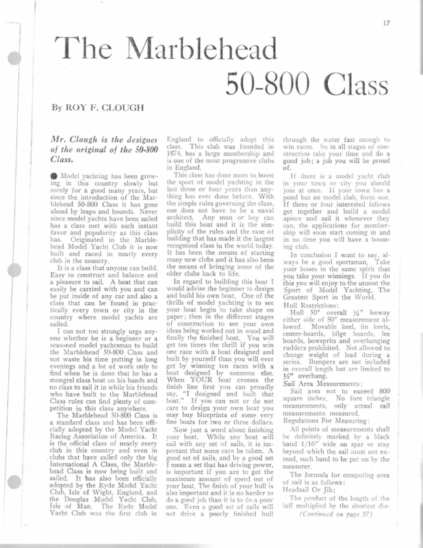
17 ~ “The Marblehead | 50-800 Class By ROY F. CLOUGH Mr. Clough is the designer of the original of the 50-800 Class. @ Model yachting has been growing in this country slowly but surely for a good many years, but since the introduction of the Marblehead 50-800 Class it has gone ahead by leaps and bounds. Never since model yachts have been sailed has a class met with such instant favor and popularity as this class has. Originated in the Marblehead Model -Yacht Club it is now built and .raced in nearly every club in the country, It is a class that anyone can build. Easy to construct and balance and a pleasure to sail. A boat that can easily be carried with you and can be put inside of any car and also a class that can be found in practically every town or city in the country where model yachts are sailed. I can not too strongly urge anyone whether he is a beginner or a seasoned model yachtsman to build the Marblehead 50-800 Class and not waste his time putting in long evenings and a lot of work only to find when he is done that he has a mongrel class boat on his hands and no class to sail it in while his friends who have built to the Marblehead Class rules can find plenty of com- petition in this class anywhere. England to officially adopt this class. This club was founded in 1874, has a large membership and is one of the most progressive clubs in England. This class has done more to boost the sport of model yachting in the last three or four years than anything has ever done before. With the simple rules governing the class, one does not have to be a naval architect. Any man or boy can build this boat and it is the simplicity of the rules and the ease of building that has made it the largest recognized class in the world today. It has been the means of starting many new clubs and it has also been the means of bringing some of the older clubs back to life. In regard to building this boat I would advise the beginner to design and build his own boat. One of the thrills of model yachting is to see your boat begin to take shape on paper; then in the different stages of construction to see your own ideas being worked out in wood and finally the finished boat. You will get ten times the thrill if you win one race with a boat designed and built by yourself than you will ever get by winning ten races with a boat designed by someone else. When YOUR boat crosses the finish line first you can proudly say, “I designed and built that boat.” If you can not or do not care to design your own boat you The Marblehead 50-800 Class is a standard class and has been offi- may buy blueprints of some very fine boats for two or three dollars. cially adopted by the Model Yacht Now just a word about finishing your boat. While any boat will sail with any set of sails, it is 1mportant that some care be taken. A good set of sails, and by a good set I mean a set that has driving power, is important if you are to get the maximum amount of speed out of your boat, The finish of your hull is also important and it is no harder to do a good job than it is to do a poor Racing Association of America. It is the official class of nearly every club in this country and even in clubs that have sailed only the big International A Class, the Marblehead Class is now being built and sailed. It thas also been officially adopted by the Ryde Model Yacht Club, Isle of Wight, England, and the Douglas Model Yacht Club, Isle of Man, The Ryde Model Yacht Club was the first club in one. not Even a good set of sails will drive a poorly finished hull through the water fast enough to win races. So in all stages of construction take your time and do a good job; a job you will be proud of. If there is a model yacht club in your town or city you should join at once. If your town has a pond but no model club, form one. If three or four interested fellows get together and build a model apiece and sail it whenever they can, the applications for membership will soon start coming in and in no time you will have a booming club. In conclusion I want to say, always be a good sportsman, Take your losses in the same spirit that you take your winnings. If you do this you will enjoy to the utmost the Sport of Model Yachting, The Greatest Sport in the World. Hull Restrictions: Hull 50” overall %4” leeway either side of 50” measurement allowed. Movable keel, fin keels, center-boards, bilge boards, lee boards, bowsprits and overhanging rudders prohibited. Not allowed to change weight of lead during a series. Bumpers are not included in overall length but are limited to 4” overhang. Sail Area Measurements: Sail area not to exceed 800 square inches, No fore triangle measurements, measurements only actual sail measured. Regulations For Measuring: All points of measurements shall be definitely marked by a black band 1/16” wide on spar or stay beyond which the sail must not extend, such band to be put on by the measurer. The formula for computing area of sail is as follows: Headsail Or Jib; The product of the length of the luff multiplied by the shortest dis(Continued on page 57)
SCENIC MODELING their shape depending upon the re- [Xvery model railroader at one time or another wishes a tunnel on his line, for they add to its attrac tiveness. Frequently there is one As stated before, the usual model railroad is built on a flat baseb oard. and at its best is uninterest ing. Un- dulating scenery always adds to its attractiveness, and the easiest terrain is of Fig. 5. ot to build false way that is best hidden. as shown in an effective concealment. It will be noticed that part the baseboard has been …It’s one of the 20 FREE CASCO PROJECTS This may be a drain pipe ar some other obstr uction, and a tunnel at this point offer s up an embank. work, ESKIMO CANOE particular spot on every mode l line to give the illusion of an undul ating ment Build wild this quirement of the constructo r. (Continued from preceding page) The Eskimo word for this light, one-man boat is “Kayak.” The woodworker of average ability can build it easily and econom- In Fig. 6 is shown how this can be accomplished in the simplest way by fastening cardboard templates to sawed away and L shaped batte ns are run cally. And it’s lots of fun! HOW YOU GET FREE PLANS The green ticket in every 25¢ (or larger) can of CASCO entitles you to any one plan of these 20 projects, absolutely free. The plan comes to you complete in every detail. No extras to buy… you get exact working direc- tions, plans, and list of materials necessary to build, in your own projects workshop, you select. the This free project service is designed for you…sta rt to use ° , Ub _ Lee wor -7 fi oop tt FRAM it. Buy your can of CASCO today, at any Hardware, Paint or Lumber Dealer. t FOLDER HELPS YOU SELECT YOUR FREE PLAN L–.. ; ests i} A woos i | Stick the coupon we J, @ FIG.G other strip of wood is run the length of the embankment. Either cardboard or wood templates are fashioned and nailed to the edge of the baseboard and the strip of wood extending at the edge of the L battens. Over these templates cloth or screen is stretched, and the “gess o” spread over the whole and painte d. Any number of types of embank- ments may be modelled in this way, describes TEMPLATES TEMPLATES 50-800 CLASS tance between luff vided by two (2). Mainsail and clew secured to the framework. LOOK Here! Wouldn’t you like a twin cylinder gas engine that When this sail is of a triangular shape the area is found by multiplying the length of the luff by the shortest distance between measuring mark at end of boom and the mast and the two (2). product divided by Battens Four battens not more than 4” ‘ong in mainsail and three (3) not more than 2” long in jib are al- lowed. Headboards , ; : – Prac- tically the same method heretofo re described is used in building up the tunnel, but one must be certa in to leave space enough above the rails to clear locomotives and cars, Construction of tunnel mouths will be described later on in these articles. a oS ares of area Hollow spars are allowed. Models must always sail measured, Spars is limited to 34”, R. flywheel and M. CHURCH Dumont, N. J. ig Profits ASSEMBLE YOUR of Send \\ ‘ 10c. No experience required. 16 new models, 10 to 20 ft.—1 to 4 per- sons. Safe, aseemtalicn sinkable. : plan & bid catalog Complete Back The gaff rig may be used on the Marblehead Class, with sail area limited to 800 inches. There is no limit to heig ht of to non- Guarantee, fit as- Ask for “Mt oney application blank. KAYAK BOAT Co. Dept. C 147 East 84th St. N. Y. City with the light, Best matertals, cut sombling kits. agent’s There are no restrictions as to Scantlings or materials. of in Delaware Ave. ob- Spars not to be included in the sail measurement. The greatest diameter spar. timer WN KAYAK :–/75 easy sail be measured as a bow and included in the sail area. as * Weight 2! Ibs., Bore 1”, Stroke 34” two cycle, 20 cc displacement. Complete set of castings, blue print and parts to build this motor, as shown for only Castings and blue prints less sundries ….$ 9.00 Send five cents for price list of products. tained by the use of bent spars will spars , could be started as a single cylinder unit and be converted at will into a twin? Well here it is. An outstanding feature of this motor is the gearless, bearingless distributor that allows this twin to be run with ONE spark coil. The lightest, most compact and powerful motor of its size. Headboards are allowed, not exceeding 34” across base. increase the Please send folder about Free Project Service, wood uprights. The framework at the tunnel mouth should be of wood, so that after the “gesso” has been spread on, the tunnel mout h can be Any di- pictures CASEIN COMPANY OF AMERICA, Ine. 350 Madison Ave.. New York, N.Y., Dept. M.C.526 Spars (Continued from page 17) and 20 CASCO prize projects. 160 THE MARBLEHEAD belowonapenny postcard. The mailman will bring you the folder that CARD CARD from the edge and secured to the legs of same. Then from these an- ; ILLUSTRATED MODELS Boucher since 1905 The complete fine for Ship Model Builders. These two new books with 96 fully illustrated pages, on SCALE SHIP MODELS, R YACHTS, SPEED BOAT S, MINIATURE ENGINES, suppli es and accessories. Send 25c¢ stamps or coin for your copies. BOUCHER PLAY THINGS Mfg. Corp. Dept. H-5, 126 Street, New York, N. Y. MOTORS & GEARS 17 Lafayette types of motors for rail- road and experimental use. Motor dimension sheet and gear list 5c. PEA LAMPS |[5c¢ up. Complete line from 4mm. up. List 5c. MODEL RAILROAD Catalog, giving above data in addition to many other items, lic. THE FIXEN LINE, 871! {ith Street, Dept. MC5, Richmo nd Hill, N.Y.
m one – then Sting ‘The Marblehead 50-800 By GARAMOND CASI JON that nters own the tock ock This Class is the result of a call for a simplified method of rating model yachts. ape as red nd @ Though the International and other racing rules may have the advantage of being scientific and sufficiently analytical to prevent a design from defeating the measure- ments of its particular class, at the same time it is rather too involved to permit the amateur yachtsman to attempt to design his own boat. Consequently, as only the published designs of others were available, the sport found itself losing supporters every year, and was fast becoming extinct, with the exception of those who had a sufficient grasp of the principles involved to permit them to design their boats. The rank and file, who are the chief supporters in every sport, found themselves so outclassed by the scientific few, that they turned to other forms of amusement, where they had at least a sporting chance of winning. (Continued on page 51) or See other ings on and draw- puyes 31. 30
——. \ \ \ \ \ AE \ ae Z/ fi) ba cod T I CRAFTSMAN MODEL THE LW LAS — ew LZ aN \ | LL “SS ROSES ed A iL ; 0)
<—] ie LTH EAD NVWSLAVAO ALL Ca}, WT_OF BOAT |LESS SPARS 1/24 Lbs I¢ TOMO TAGOW ZHI AIS kn TS
LONG LIFE FOR LUMBER A Big If lumber is to be used in damp Or exposed positions, its life may $1 Book be prolonged indefinitely by giving it a treatment beforehand. In many cases, this treatment prevents the use of paint or varnish afterwards. fie oe = Authorised by Makers of Stanley Tools If, however, the lumber is laid on If you work with wood at all— whether it’s making models or furniture —you'll find this book valuable and helpful to you. A book you will use all the time. the direct rays of the sun, being painted with boiled linseed oil un- til thoroughly impregnated, it will be found that any of the ordinary finishes may be applied after the oil has dried thoroughly. Gordon Wesslund. Gives complete information on how to select woods for particular job you have on hand, tells how to use and care for tools, how to use materials best. Also contains drawings and instructions for things to make. Tells how to plan your own projects. All kinds of practical hints and helps for the home craftsman and woodworker. Over 150 illustrations. 185 pages, durably bound in blue eloth. 50-800 (Continued from page 29) Finally, a member of the Marblehead Model Yacht Club decided that a simpler rule was needed, if the sport was to continue to exist. Thus was the Marblehead 50- This book sells for $1. You may have it absolutely free of charge. Read special offer below. SPECIAL Send 800 Class started. The conditions were simple—not over 50” overall; no fin keels, no’ Model is quite It is at expiration practical, is the of lead weight, cannot present valuable subscription. book S j - month uly-Aug. g gy gy is Mail gy book, P| g Start FREE! How to Work subseription a G NaMO P| getting Model you'll get this a ‘combined: Craftsman is tasue; published y , Enclosed is $2.50. Enter yearly subseription for Model Craftsman for address given below, and send me FREE eopy of the $1 @ Street: With Tools and Wood. with............ issue. sicresccrs so 56 wesnase ws 5 3 5 wMIEEGOMEIEErEYS spss & 5 ss 6 SLRS FES 5 SRR ae | City .........--.0000-. State ........ MODEL RAILROADERS observation, solarium, ten, twelve and sixteen section sleepers. Also baggage, postal cars, diners part you need. Send 25¢ for our 84 page most helpful book ever Data published. 1564 W. Pierce St. Book and Catalog. It will help you in planning W. K, WALTHERS and 9” x 30”—36”-48” PRECISION METAL LATHE 3 i price-range of the small shop by “AMERICAN” engineen Lathe guaranteed accurate within .001”: hollow spindle ? lever-action tail-spindle, types for all @ SEND . tionally . 10c for it’s the PARTS AND ne trades available at corresponding FOR AUTO-FEED bushed bearings; hand-feed entin length of bed; hed eroune and polished steel ; ae of all bullding. Milwaukee, Wisconsin ® Precision heavy-duty professional equipment has finally been brought within the the ow rca gues peas us Sek — Aeee chuc -25; 8” face-plate -75; too holder $1; countershaft $6.75. 30” overa. Jength; for 36” length add $1.50; for 48”. add $3.50. ATTACHMENTS FOR GEARED AUTOMATIC REVERSIBLE POWER FEED 003” per rey. and gears for cutting 12, 13, 24, 26, 48, 52 and other threads, $9.85. Additional GHAK-TKAIN to cut ALL threads 7 to 84, $5.20. Send 25%, shipped COD for balance, FOB, N. Y., Wt., 80 lbs24-page Catalog low-priced power tools and ‘72 WORKSHOP AMERICAN POWER TOOL CORP., of other accessories and PROJECTS AND PLANS.’’ 80-C-4th Ave., New York. N. entire line of sensa- Y. The method of building is identical with that given for the 36” yacht a few months ago, and so will not be repeated here. The hull should be not over 3/16” thick and %” would be better, if the skill of the builder permits it. and coaches for N.Y.C. Pennsylvania and Southern Pacific. We can supply the parts, construction sets or comolets oor Our contract department will build and install a complete model railroad system—or any deter- mined until the hull has been built and weighed. This boat may be built either in lifts or planked. About two Ibs. is left to be supplied as loose ballast—in ‘the shape of small weights, fastened to the frames—so that the trim of the model may be changed to that which is found by experiment to be best. of N évake BO ircinl Moder this The largest, most complete line of 1%” scale Model Railroad Equipment ever offered. Everything you need for building track, signals, freight and passenger cars and scenic accessories. Also a full line of control accessories and many hard to get materials. The highest quality merchandise at production prices—All made in our plant and carried in stock. 20 different styles of freight cars including flat cars, gondolas, reefers, box cars, cabooses, hopper and tank cars. Seven different Pullman cars including club, parlor, This and be subscription ATTENTION rather shorter on the finished regular i MODEL CRAFTSMAN, Dept. W-115 ; 330 W. 42nd St, N. Y. C. to (In Canada & Foreign Countries $3.00) L.W.L. than the average, has a little more beam and should be a fine light weather boat. The long overhanging bow, with its rounded sections, gives an extended waterline when heeled, thus enabling the boat to use the added drive of the sails to the best advantage. The straight-sided keel should be made of whatever thickness is required to bring the total weight—less amount at subscription NOW. You'll be sure of Craftsman avery month and sufficient mast and sails—to 12% lbs. Craftsman OFFER yearly coupon today. We'll take care of subscription and rush book to you promptly. Hurry! Take advantage of this great offer to keep the boats fairly similar in design, without preventing the man with ideas of his own from testing them out in club racing. The design shown is from the board of a British model yachtsman. one A year’s subscription to MODEL CRAFTSMAN is an excellent Instead of wondering your problem. what to give your brother craftsman gift for to the model builder. Christmas—let us solve Send us his name and address, together with $2.50, and we will send him a gift card notifying him that a subscription is coming from you. This gift card will reach him the day before Christmas. ACT NOW, and avoid the RUSH. MODEL CRAFTSMAN Cn rule only Subscription may be your own or a friend's, and ean start with next issue or sail area. May the best sailor win, instead of the best mathematician! Probably over 1000 of these boats have been built since the rule first came into being a few years The us price of $2.50, and we will send you $1 book, absolutely free of charge. outboard rudders, not over 800 sq.” ago. “How to Work With Tools and Wood” blocks or trestles and exposed to MARBLEHEAD FREE! l Subscription Dept. C-115, McGraw-Hill Bldg., New York, N. Y.
Aaa rg Me, CE SRO ~~ By E.. J.‘HESS splintered The cabin and sail hatch are “cut lihood of there being .Thisache“pelongioggn the In-A small holes. the of some on the edges to glued and y, of. from mahogan / ae ees ternational 6 meter Class, is one ieee shen ai a Hae i deck before the mast is rigged. The.disc ofbluish paper should be at placed iin the hole, about 1/64” from - model, . though only 9% long, is fore or sail hatch is set in place the edge, to simulate the reflection kept” be “strictly to scale, and, ‘having lead the same time, and should is set. on the glass of the port. glue the ballast, may be sailed”in smooth under pressure until rudder is cut out separately, lead, ‘The from cast is which The keel, ee z aaa ee ee 3 Be. best known of her ‘type. The - The hullis built up saith regular water. x fu: jeslayer system, from thin pieces of » me mahogany, with a slightly thinner © piece of white wood inserted to form the waterline. This method obviates painting, the cause ofmine out of ten small models lacking that “pro- _ fessional” touch, which goes so far towards© reproducing the (original E aeappearance. “All that is necessary is = 2f0 ‘sand down the. block as received, . “andgivea couple of | coats of goed -yarnish, = Thelifts are shownin the full size drawing, for the benefit of those who wish to cut out their own model, the deck being made of white wood to show the planking, which is drawn upon itif desired. It is not advised a “that too-muchssmallidetail-be. shown ‘inSo- small a model, soyall“pulley” caghtge blocks have been omitted, as they pipulcepa teat be.‘too, small, for, ac- | case. The curate’ finishing. in” afty Aa “riggingis from two different colors OF thread, black for ‘the standing, 2 and: grayfor the running. rigging. +. Thearrangement, of the; cordage is Telit shown in.‘both the ‘drawing and it photographs, iit is®the conventional suchiat close replica of the. eo einal “Tanai? that it takes This little inadelsie ing tion to see oe difference. It is probably the smallest sail close observa MEE gt Shs pm Ae ay scale model made,moet holes drilled and glued in place with waterproof - Marconi rig; and should give no par- should have two fine then set in position glue. It is for appearance. made ticular trouble to rig. The fore and ‘through it, andis The mast and boom are fine headless back stays should be rigged first, and and fastened with small slivers of wood, with a from Itis sanded down the braces, from: the, foot of the brads and cement. ly straight grain. The best perfect h finis th a smoo _mast to the crosstree and back to the with the hull to give tiller is bent from method.of rounding and taperingg “mast, rigged next. The shrouds are to the joint. The it in a drillin fine wire, and set in a the mast it to mount rigged last, after the sails shave been a piece, ofdeck. spinning while it sand and e, . It should overhang machin holein the a ” fastened in. position. modern the of is boom The . rapidly t 14”. The cabin The mainsail is held tothe mast the cockpit by abou of coat one both Give type. flat ng by bori by.thread, stitched through the sail portholes are best made block, before it has varnish. and,round?the mast, gray thread be- small holesin'the its final size, _ ing) used.»The~jibstay_ is ‘black been trimmeddown to be taken oft ais one, great care shouldbe taken to /32" thread. The“boom is held to the leaving’about1 made, as to keep the knots as small as possible. mast bya ‘single thread,.passed after the holes have been s sharp.. (Working drawings for this model - edge ake‘fine hole and‘then round thiswill leave ‘thevery erentlike- on me 3 two pages.) rwise ere is a In rigging a small Zaadlel such as Othe
F”se L||PN rU. —Nn xra a x) S 9 CRAFTSMAN MODEL THE y, A \ NY + ETN t. 6S su sail ng 1”from \
MODEL THE CRAFTSMAN ff x / / = ol Q a 2 SA a & FollSize - Rx 6 Diam ee eS SSS SS TSS Drawn Dy UW JS Creer
as can be obtained in almost any locality and the tools those possessed by any model craftsman of average means. The directions, though quite concise, have not omitted any of the necessary steps and the builder will find that by following them in the order given, work will progress rapidly and easily and nothing will have to be HIS size and rating of a model yacht is probably the most generally popular of any of the com=. moner classes. It is neither too small to be raced in rough weather nor is it so large as to be cumbersome and un©) handy to carry home after a day’s 4ie sailing is over. The construction is of the conventional layer system, consisting of a done over again, because of having et number of lifts glued together after been done too soon in the first place. The most important thing to remem- The “~~ having been sawed to shape. lines of this boat closely follow those -of the larger Long Island Sound ber is that, due to the fact that this boat is of light construction, the materials must be of the best, though not Yacht Club vessels, and for this reason a fleet of these boats has a most realistic appearance when racing on a necessarily of the most expensive kind. Any good dry lumber to be found in the lumber yard will answer the purpose, provided the grain is not of the lake. | _. The list of tools, materials and hardware is herewith given, and it will hard, upstanding variety, and_ that there is no gum or resin in the wood to seep out afterwards and cause the be seen that there is nothing special --. called for. The materials all are such SHEER SHEER ie, al “s - DATA: LeaAo BALLAST RATING = 18 es if it \\ \_ Bosy \ AFTE —— Pes 200z Weignt pF HuteSAILS, FITTINGS -/6 02 RS, WeicnT of SPA LINE SE raat a fh S TOTAL WeigHT— 4& oz 2S ZF xX 24.5 = 2 20 Pa LEAS sr HALF BR WATERLINES R CentTeR LINE
TH E cht painting. ost any loyossessed by % 2 ct that this on, the ma, though not. yvensive kind. be found in s not of the. ~ -, and that in the wood ? id cause the © SHEER plan on stock, pricking through where water-line station marked. fore pricking through. ro osran proren | >> Draw outline of lift using thin leaneea at seocs BS FOR DECK. TESTING wire Bean Momo taken to see that the knots and resinous spots are still completely covered after the sanding is finished. crosses Check all lines and marks closely be- Tea Way To Proromrion Sain Torcness Plane working-face on each lift. ~ Mark for recognition. Plane working-edge on each lift. ~ Mark for recognition. Gauge thickness 44” on edges and splint to strike curve. Fasten two halves of each lift together with 114” wire brads. Match working-face and working-edge. : Locate fore and aft points and point at station No. 9 for curve denoting ’ inside waste wood line. Draw curve. Square marks across working edges’ of both halves fore and aft. Check to see that all ends of lifts. Dress each lift to thickness with plane. Make sure they are perfectly smooth and free from wind. Mark each lift for recognition, four above load-water-line, and nine below lifts are marked for recognition. Saw cut lifts to shape, inside and out. This may. be done on band-saw, if one is convenient; or with a turning saw, saving outline marks. ¥ – Nee FH. Scae wey BEANS FASTEN load-water-line. Wasnen Lay out each station, 1 to 17, by superposing lift on plan. Mark all Remove brads. Twe War To ESS wang No 0-32 UNOLm Lay two halves of glue. ready to apply HEADS lifts. each lift out Square station lines on faces and Apply a water-proof glue, paper under joints fore and aft. Mark stations for recognition.- two parts of lift firmly together and + edges with try-square. using Press PLAN im r to remem- ; It should then be sanded ING nem in the ress rapidly | have to be . of having . first place. 9 Lay out water-lines on one-half of we —— ; | FORE Boor Lwl. i a builder will ® * _ each lift by superposing half-breadth off until entirely smooth, care being average 10ugh quite any of the ver the pur- CRAFTSMAN paint to peel off. If the builder is so -& situated or so unfortunate as to be unable to obtain a wood free from resin the finished boat should be given sal © at least two coats of shellac before of MODEL . leer Line 2 tTraATITit Lirtitil 3 i ; SeeOFINCHES.g 2 # ) 2 I biti | FADTH PLAN ty‘ % ‘< t oF : ews oyteary ee Fey + wes UN
THE MODEL CRAFTSMAN 10 BILL OF MATERIAL FOR LUMBER DEALER OR MILL AND DIAGRAM OF SIZES Item Hull -- Hull Hull Hull Hull Hull Hull Hull “Hull Hull Hull Hull Hull No. of Pieces Thickness Width Name of Part Lift No. 2 above L. W. L. Lift No. 3 above L. W L. Lift No. 4 above L. W. L. Lift No. 1 below L. W. L. Lift No. 2 below L. W. L. Lift No. 3 below L. W. L. Lift No. 4 below L. W. L. Lift No. 5 below L. W. L. Lift No. 6 below L. W. L. Lift No. 7 below L. W. L. Lift No. 8 below L. W. L. Lift No. 9 below L. W. L. 2 2 2 Z 2 2 2 2 * 2 2 2 2 Rudder Deck Beams 1 3 4” 34" 2 Lift No. 1 above L. W. E. Length 2976" 3336" 3518” 1518” 25" 2175” 1814” 1544" 1316” 1154” 97%," 733” 354" 4” 4” 4” 3%" 314" 244" 14" 3," 4" te" 5” yy" 34” 34" 4” 34" 4" 4” 3" 34" i" 4" 44" to” Note: Each Lift consists of two pieces, one on each side of center-line. Hull Hull 1 iy" 8” 38” Vy" 34" 7 2214" 10” 12” 3” 3” 24" 2,” 16” 16” 16” 2! Hull Deck Spars Spars Cradle Boom Club Bottom 1 1 1 yy," 32" 34” Top Bottom Sides Ends 1 1 2 2 4" 4” i" yy" Cradle Mould Mould Mould Mould Box Box Box Box 4,” 5 44” 2 Shores 4614" 34" 4" 1 Mast Spars 6” 8” 134” 114" Wy" in" 1. White pine used for hull lifts, deck, deck beams, rudder, mast, boom, club, and mould-box. 2. White pine, mahogany or white-wood used for cradle parts. 3. The sizes given for hull lifts are exact for lengths, vs” is allowed on ofthicklifts nesses of lift stock for hand dressing of faces, 44” is allowed on widths to prevent flat spots when laying out waterlines. 4. Watch for end checks. Cut lifts out in a way to eliminate these. 5. The sizes given for mould-box are exact. 6. Spar sizes allow for waste. After smoothing. hull with cuttin: tools, start sandpapering, using No. 114 paper at first, and finishing wit! No. 00. Rub across grain to fair ou any unevenness, and going with grain to smooth finally. Bore holes for kee! bolts at stations 8-9-10-11-12, using Y%" augur bit. Locate lead line, and mark, allow- ing for a saw-cut. Whatever you remove with saw and plane must be re placed by addition of a thin piece 01 top of lead. Dress bottom of keel. Secure block to keel for holding “in vise. Remove block from deck-line. Mark sheer-line at each station wit! wing dividers from water-line. La) off line with a thin spline. Rough down. to line with drawin; Dress wit! knife or paring-chisel. plane. Gauge a line around deck at shee: using marking-gauge, 5” from edgc Gauge 134” in from transom or sta tion No. 17. Start hollowing inside of hull usin; Skin thickness when com gouges. pletely dug out is 1%”. Sand gouge marks out with No. . sandpaper. 7. Cradle sizes are exact. drive a 1” brad at each end to insure parts staying in right relation to each other. Make sure surface where work is assembled is a true plane. Remove all glue squeezed out of joints before it sets. Allow twelve hours for drying. When glue has set dress joints smooth with plane. Assemble lifts, in sections of four, and | then clamp sections Pe ie together. T ar ~ pointcurvéfore waste Afterwood Check all station marks carefully be- ere The way toformark one reco el Secure block at deck-line for holding boat in vise as shown. Start removing arrises (corners) of lifts using chisel, spoke-shave, and plane, continuing operation until all waste-wood is removed and waterlines present a fair appearance. Be careful not to under-cut waterlines. 212 1 14 = ~. SS fore allowing glue to set. ASTEN CALAT “Sroce TOR ATAPS wirn Two 3"-Na/0FH Wooo peat Ni Aaa ASTEMOLED BLOCKS FA Woo Screws. TO MULL 10 wirn Six &$°-No é Buscn 242 srock Fasven To svc. wirn rwe 3°-No/0 F-Woeo Scare Ae Al - LF 42 3 Vy. os NS ~ % 6 Nt . stations ths for each lift given in bill Leng of material for mill. sions for fore and aft points Dimen of waste wood curves given here. 5 \is 4 = T . 1/4 7 €L 7 10“9 9/16" ba 7 3-8 7/8" 3/16" 4+8 5) £4, {2} (6: is ta & Pore nee oor” a leck at sheer, “ from edge. msom or sta- ‘of hull using ; when comt with No. 1, CRAFTSMAN 11 Fit deck-beams ‘at point where fore-stay touches deck, at center of mast, and where rudder post comes The beams are rethrough deck. holes for keel © mark, allowThatever you | MODEL testing with “Beam Mould” frequently. Apply deck and test to insure a tight fit. Give inside of hull two coats of spar varnish. Smooth pattern for lead ballast carefully. Give two coats of orange SCREWS, BOLTS, HARDWARE, CLOTH AND PAINT Name of Part Washers Brass, Description Quantity 14” Screws Nuts Machine, Y,”.2-56 Hexagon Brass, Nuts Hexagon Brass, Bolts Wire Wire Rod Rod Rod Sheet Tubing Tubing Screws Screws No. 10-32 No. 3-48 Brass stock, No. 10-32 Brass stock, No.37 Galvonized iron, 10 2 12” 24” 1 spool No. 22 Brass, 16” diameter 3” Brass, 3%” diameter 1,” Brass, No. 18 10” Brass vs” thick 3” x 8” Brass, Seamless 14” 12” Brass, Seamless x0″ 14” Wood, Flat Head, Brass 14” No. 2 1 gross Wood, Round Head Brass 4” No.2 18 Screws Wood, Glue Paint Paint Varnish For underbody Spar Lead Lead Cambric 5 3 Flat Head, Brass 144” No. 10 3 Waterproof 4 |b. For topsides White 4 pint Y, pint 4 pint 4 Ib. Plumbers 4% and ¥% 5 Lonsdale Ibs. 14 yds. Fastin Te nee p Ste KE Mee 5 3 4 14 9/16″ 12 . 3/4″ ese < Un Be: Pa pa pa = 3) els rs, 5 Forward point for waste wood curve. Thickness at keel. Keel line, at as oe By
12 THE MODEL CRAFTSMAN shellac, rubbing down .between coats THE hay bb MAKE SAlbeS . EeAoN with fine oiled sandpaper. FoLoInG Make mould-box, fastening sides to ends with brads, and have top and bottom secured with 14%” No. 8 flat- head wood-screws. Remove top from box. STITCHING Aras aig last mould the 14” “ « face and auger-bit through holes in mould the proper angle will be obtained. Feical = Place bal- under bore holes through top. By running iN a against Push 4” maple dowels through ballast mould and top holding them together. Screw top of box in place =" with mould ¥ out screws. in position. Allow dowels to project 3¢” through mould at bottom. Remove bottom of box by backing Main sare ' Give ballast mould a thin coat of 2 machine oil. Prepare moulders sand, dampening it so it will pack, and ram up mould. + ( Ao ay CLew Tack Refer to sail and spar plan for dimensions. Lay cloth over outline. double. be Tack bottom of box, setting Remove top of box. Tap ballast Layout shapes on heavy paper. Cut edges with allowances for folding. Turn corners in. Replace screws home. mould lightly Edges to be to loosen Take mould out Stitching to be doubled from head to tack and from tack to clew. from sand. ; , Replace top of box, and secure with THe War To Mane FITTINGS Bows cr TRaveccen wt. CO)» aa Tr ee es Me2 fap hk Toknee i —, Ce Lacing = py ni , eZ | No aT Wine <——_— aia Eves No. 24 Wine y uy { Mypoen Sroce a “toe Twe -2ourco PR Dany amo Tat rom o7 Mare wire Gawwanizeg "APART OH FAST AND IZ” APART ww z Ne Mast BA os Two Raquinco.onwe & vgs. on sa |es / —Si-—— i ~ aot m3 jp [cA SS © Howe For ze t=-3-7+ C= HARK: E-CENTCRIPUNCHT 2-BoRE USING TWIST DAULL J TURING Fd sLtowL.y a> lO I EAS srocn.2-HoLo =o iN SMOorTrm JAWED VISE, BENDING WITH LIGHT EVEN or 1d land Nedaseapecte MEAYY BLOWS Front HAMNMEA Fermnvuce ; yee it =O oa voIne0.e-APPLY FLUX. Sevetee END TOES NER — Ses 4 2 Wold Datei wien Boning Fem Fone Stay Hook r > =} Cc Bone 4 \Ve <= So.osnco wane ast STEP fenove : MESe BEtihe “ie re pay «it Woo Senew Et, 4 ———— on Po) 4 Ane Yo] ToOLne ’ Owe Raqune G MOL dD: * LranTaening —, “Co 7 S.oT uw“Meet of flaer Te FITSTe Sie a, 2ae 44 AN® TA 2-56 ron £°NE No. SCREWS ‘ 3 ¢/ Tt . ron Neo 3° Bs lH deisel 3 8ne0 4 iie if a nar ial eno “ene a i r rin Foxe YOTANE Ticcens Re 1 pean Sir aaroine rie 4 Drs nencmvest®) recs 4-6 | pet eS tne Housing iy is) wits 3-48 RH THREAD . Lt Ss f=... Joroer mere CATCHING No IT wine THREADLO Ea ie 3-68 LM. Twneae Dace ron & Ojeve re rane No 37 Wine z:~Ned Weeo Use No. t# 2eouintn. TAPPING OnesTweexronn prey Coe Bar aie =a fya Te vaKxe Ne 37 Wirt MoIT Wire. THAEADLED ASR foareMNENaan. etre needt-He Seas [avant Rvucoen Heno YANO YGHLE ©, im = No 48 Dane 2 — Use eerone TArhiNG 7 Ti CLEAN USING FILE. © Ticen re BS so0.ocR. 5- DRESS JOINT i as .; ° at” » JOLcEaing I-CLEAN PARTS TO BE Seat tesa aa : Owe nequinets. Sowoaen riange TO rvee Cur ceaut Or Tupe Away DAL AND CounTEA- Sih ALLow Ye Paova ABOVE COCK. MARE FLANGE PLATE FIT BOSS tm mee. Posie Tor or rusk FLUSH wire CCR mare ‘Ne.io Wooo Scaew TOUCHING wiITe wiREe : ° 5 He L woow scaews TwooFAcqunmco BorG 10.8 SCREW. HEAcon. w3-DRESS SOLDERING-IRON. Pon SOLDER SHAPED 4-AppLly IRON TO WORK, Hoon IN Owe REQUIRED .Watt OF | FOO Teame wirw maave wees Sey wane Semaw CATICG | Usa FoR merac.3- TAP FOR THREAD £2. FONG LIE me RANEEES ‘ MAKE oF 4 O No 10Wooo Senew ORLLING ANO TarriNG— One FEQUIFAED. Wace : Tw on £quimeo CLOTH AND STEEL WOOL -j————_ } — PORT . Fic €.4-POLisH WITH EMERY Seoener Sie Ween Sne weceive 3-44 Twnean TO OUTLINE.WITH SNIPS, 4. F3.GAVGE HACK SAW OR JEWELLERS saw.3-DRESS EOGES wiTH IN ; No 2- 2° RW No ST WARK FIN I-Lay ouT SHAPE 2“Cur TyRN Ponr Generac ~ San ae _Direcrions - No STW. Ona equines fAMLESS. Denne Batt Saee. HAPIN' Wo 2-56 Cincmime om Reo gixao re | Sng Bo.r ex Rusecn Crain Peare a of fi Coy mm OREN To macatve oa Two Requnto . - LOG. LONG ANO Owe #” MOLES Ts Ane Prace ween Temnene T Net — Feces ve rane Tian Ban _ Firregs ro se mace NOLE-Ace or BRASS.
THE etw tween coats { THE les to | nin ave ww)P and : Ad Pad f 5 ; m No. 8flat- § |.ale. CRAFTSMAN Way To MaKe % SPARS Pi % : : Place bal- 465 ; PLANE STOCK STRAIGHT AND SQUARE. GAUGE CENTER-LINE ON A SURFACE AND ENDS : er face and , me a By running igh holes in | eal } through 3 ;L Vee ‘ ee sof | = - will be ob- els. MODEL LAyouT CuRVED TAPER on Bano D SURFACES FROM X TO MASTHEAD. PLANE TO TAPER NARKS holding them box in place Allow” tion. rough mould © LayrouT cvRvED TAPER on A and C SURFACES. PLANE To TAPER MARKS x by backing | thin coat of 2 oa d, dampening am up mould. + box, B \ 53 = Boor ot ‘ L 6 PLANE STOCK STRAIGHT AND SQUARE. GAUGE CENTER-LINE ON A SURFACE Tap ballast _ AND ENDS 5 n from sand. : : e Fh jae TO i be + f ;By nd secure with —+. 7£" + Layour CURVED TAPERS FROM x ToENOS ON Band D suRFACES. PLANE TAPER MARKS ae fe Tocn A Dare ann Tar eal 3 eo 2-56 Pacmime ie a4 2azt ‘ Weis setting ' = ‘ Soman 4 Layout CURVED TAPERS oN A ano B SURFACES. PLANE TO TAPER MARKS aoe vt f SX so) Nore: Use sane (leTHOD WHEN MAKING CLUB AS FOR Boon. RErFer To Salk AND Io Sear PLAN FOR THE LENGTHS AND OF TAPERS DIANETERS. _Bacn surrace or Masr ANDO. TOP SURFACES OF Boom Ano Crus To ec at| ©) ae) @ STRAIGHT ©) LAYOUT AN OCTAGON ON ENDS OF SPAR BY MEASURING HALF OF THE EACH USING CORNER screws. CONNECTING wiFH SANDPAPER Push dowels into place, mak- ing sure they reach sand at bottom of mould. Melt lead, testing heat with a pine When stick chars, pour metal. Smooth casting using a spoke-shave, _ Stick. TINGS -u0 BE MADE _ f@ i ACROSS PENCIL. AND FINGER. PLANE RouND. Finish ; AND file and sandpaper. THE CORNERS. GAUGE OFF CORNERS. LENGTH YNTIL face two coats of spar varnish. and secure rudder port using white lead between flange and hull. re Place and secure ballast with nuts and washers on inside of hull. Remove white lead Place | Coat top edge of sheer or deck line of hull with white lead or varnish, if squeezed out brass ~ Counter-bore for bolt-heads. of keel. Sandpaper smooth. Dress top face of stock for deck, Place and sandpaper smooth. 10-32 WHOLE CORNERS Coat top face of ballast with white lead, applying same to face of keel. threaded using EACH SIDE OF and solder them into casting. and dress casting to conform to shape bolts THE ConTINVE To REMOVE Make five keel E. Stock. DIAGONAL LINES Give under hull is to be finished bright, and set. deck. 3 Bore for 1%” No. 2 flat-head screws using No. 50 twist drill. Ream holes (Continued on page 78)
THE MODEL CRAFTSMAN Bettendorf Trucks 20 Rater Boat (Continued from page 7) (Continued from page 13) size she will rate in the ““R” boat class of the Model Yacht Racing Association of America. x ~. come from.the possession of a really in .. efficient Counter-sink cquipment of rolling stock. No. Arrange screws deck to hull. + than those which are merely equalized -. by means of a screw in the centre. ~ Besides which, they cannot, even -under the roughest conditions, fall ‘apart in operation; which is an ever present danger with any sort of small __ rolling stock held toge ther by screws. - After the castings have had the - roughness filed off the outside, so that they present a fairly smooth appear= ance, the centres of the axle bearings -are laid off, being 44” on each side of ‘a vertical centre line. These holes are ~~ then drilled about two drill sizes larger than the axle to permit it to operate freely when the frame rocks. The cross bolster is then marked with a centre line on the top surface and the ~~ centre is punched. With this as a centre, and a distance of 3/64” more ~ than half the outside dimension of the wheels as a radius, a scratch is made -.across each end of the bolster for the inside edge of the slot in which the |. frame rides. Another mark is made the thickness of the frame outside this and the metal removed with a file. When both ends have been worked on the lower opening in the side frames is filed out square until it is just large enough for the end of the bolster to be pushed through. Then the upper half of the opening is filed to fit the groove in the bolster, with only enough play to allow the frame to rock about he 14". Two small holes are drilled through the upper and lower bars of ~ the side frame and through the bolster, *-after which those in the bolster are enlarged about three drill sizes. Small springs are wound up from hard brass “wire and are inserted, after which the retaining wires are soldered in place and the truck is ready for the test. In my latest trucks I use a strip of ~ thin sheet brass below the springs and - on top of the lower part of the side frame, as this stiffens the construction a lot. The ends of the brass are bent - down on the outside for about =”, as shown in the photograph of the as- ~-sembled truck. This type of truck § is well adapted to the ready made = . wheels now on the market. 43 heads —- car does not have to be lifted over ~ every small “hump” in the rail, these ) with ~~’ Probably because the weight of the ~ trucks pull very much more easily Wy deck twist below drill. surface. 1” apart, and secure Wipe away white lead class of the M. Y. R.A. A. Born in the Wind-Tunnel (Continued from page 16) squeezed out. Trim deck to conform to contour of hull at deck. | Sand deck absolutely clean using oiled No. 00 sandpaper. Give thin coat of white shellac. Lay out deck planking with India drawing ink. Sand again. Give three thin coats of spar varnish rubbing down between coats with fine oiled sandpaper. Secure projecting half-section of rudder-post to after edge of keel or sternpost with %” No. 2 flat-head brass wood-screws. File heads flush The model when en- larged will also rate high in the “D” consisting of a-supervisory line and a control line. The supervisory line distributes the air to the reservoirs under each car and-charges to the maximum pressure at all times. In conventional brakes it is not possible to charge the reservoirs during brake application. The purpose of the control line is to apply and release the brakes by admitting air to the pneumatic relay valve under each car, this valve controlling communication between each brake cylinder and its adjacent reser- with surface of tubing. voir, Paint hull, applying same in thin coats, rubbing down between applica- atmosphere. This control line passes from the engineer’s brake through the tions until a satisfactory surface is and from the cylinder to the decelerometer valve to the relay valve. obtained. This briefly describes the pneumatic Make spars, watching direction of grain, as it will determine the future straightness of these parts. Bore 7%” operation. Parallel to this pneumatic circuit lies an electric circuit actuated hole for corners of sails. Give spars three coats of spar varnish. Make fittings. nickel-plated, If these are to be hard solder must be used in making joints, as the softer alloy will not hold under plating heat. by contact points on the engineer’s brake valve, which operates a magnetic control feature on each pneumatic relay valve. This not only synchronizes but accelerates all brake applications and releases. of The result is a brake exceptionally quick and sensitive Place and secure all fittings. The main-traveller goes 3” aft of center of rudder-head, the jib traveller 214” for- response so desirable on a train travel- ward of the center of the mast. The chain-plates are placed 134” aft of completely existence, as with all windows‘and out- center of mast. Locate and place forestay-hook. Bore hole large enough to permit passage of screw at bot- side tom of same, and cover with a brass plate directly over traveller aft. Bore for and place a 1%” brass screw- depends upon the air conditioning sys- eye in boom directly over traveller aft. Do the same in club over jib traveller. Make sails. Be watchful that Lonsdale Cambric is not distorted when ing at the rate of 146 ft. per second. We believe that this will be the most doors air conditioned entirely sealed train there in is practically no air infiltration so that complete control of inside conditions tem whether under heating or cooling. This will be accomplished by distributing filtered, heated or cooled air through a system of ducts by means of power driven blowers. These ducts smoothed out preparatory to marking. extend the full length of both coaches, and have flexible insulated connections Seize or sew sails to spars, drawing between the two coaches. This permits them out to correct dimensions care- of the use of a single electric driven fully. compressor cooling plant as well as a Use No. 24 thread, waxing same, Rig shrouds and forestay. Step mast, set up on turn buckles, and rig sheets. No. 22 galvanized wire is used for shrouds and forestay. The lightest silk fishing line for sheets. Note: This is a model “R” boat designed to a scale of 1”—1’-0”. If the dimensions are increased one-half single oil burner heating plant, both located in the baggage space of the power or front car. The heating and cooling ducts are so arranged that when either is used for delivery of air to the cars, the other is used as a power driven exhaust; thus positively controlling both input and output of. air at all times. Temperatures are ss 78


