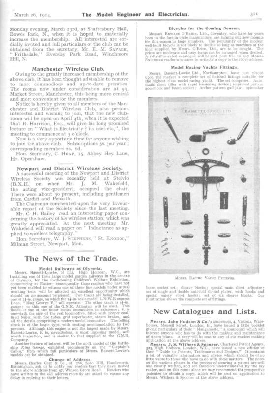
- Racing Yacht Innovation: To cater to the “highest class” of model racing, Bassett-Lowke Ltd. introduced a complete set of finished yacht fittings. The set featured advanced mechanical aids, including an automatic sheet tiller with a rapid tensioning device, “Archer” pattern gaff jaws, and anti-fold shroud plates.

March 26, 1914. The Model Engineer and Electrician. Monday evening, March 23rd, at Shaftesbury Hall, Bowes Park, N., when it is hoped to materially increase the membership. All interested are cordially invited and full particulars of the club can be obtained from the secretary, Mr. E. M. SavaceE, “ Frithsdale,’’ Eversley Park Road, Winchmore Hill, N. Manchester Wireless Club. Owing to the greatly increased membership ot the above club, it has been thought advisable to remove to more commodious and up-to-date premises. The rooms now under consideration are at 93, Market Street, Manchester, this being more.central and more convenient for the members. Notice is hereby given to all members of the Manchester and District Wireless Club, also persons interested and wishing to join, that the new clubroom will be open on April 4th, when it is expected that R. Harrison, Esq., will give his long promised Bicycles for the Coming Season, Messrs. Epwarp O’BriEN, Ltp., Coventry, who have for years been to the fore in cycle manutacture, are turning out new mounts for this season in large numbers. The popularity of the modern well-built bicycle is not likely to decline so long as machines of the kind supplied by Messrs. O’Brien, Ltd., are to be bought. The prices are moderate and easy terms can be arranged when desired. A fully-illustrated catalogue will be sent post free to any MopEL ENGINEER reader who cares to write for a copy to the above address. Model Racing Yachts Fittings. Messrs. Bassett-Lowke Ltd., Northampton, have just placed upon the market a complete set of finished fittings suitable for the highest class model racing yacht. The set comprises: Automatic sheet tiller with rapid tensioning device; improved pattern gooseneck and boom socket; Archer pattern gaff jaw; spinnaker lecture on ‘‘ What is Electricity? its uses etc,”’, the meeting to commence at 3 o’clock. Now is a very opportune time for anyone wishing to join the above club. Subscriptions 5s. per year ; corresponding members 2s. 6d. Hon. Secretary, C. Heap, 15, Abbey Hey Lane, Hr. Openshaw. Newport and District Wireless Society. A successful meeting of the Newport and District Wireless Society was recently held at Stelvio Wakefield, M. J. Mr. (B.X.H.) on when the acting vice-president, occupied the chair. There were about 30 present, including gentlemen from Cardiff and Penarth. The Chairman commented upon the very favour- able report of the Society since the last meeting. Mr. C. H. Bailey read an interesting paper concerning the history of his wireless station, which was greatly appreciated. At the next meeting Mr. Wakefield will read a paper on “‘ Inductance as applied to wireless telegraphy.”’ Hon. Secretary, W. J. STEPHENS, ‘‘ St. ENoDoc,”’ Milman Street, Newport, Mon. The News of the Trade. Model Railways at Olympia. Messrs. Bassett-Lowke, of 112, High Holborn, W.C., are installing one of their large model garden railways in the annexe of Olympia, for the forthcoming Children’s Welfare Exhibition, commencing at Easter; consequently those readers who have not yet been enabled to witness one of these fine models under actual working tests will be afforded an excellent opportunity which should on no account be missed. Two tracks are being installed, one of 7}-in. gauge, on which the 14-in. scale model, L.N.W.R express Loco, “King George V,” will operate. The other track is 9$-in. gauge; on this one of the G.N.R. Atlantics will be used. This model is one of the finest model locomotives in existence; it is one-sixth the size of the real locomotive, fitted with proper coalfired boiler, with fire tubes, grid superheater, steam brakes, and all the details comprising a modern model locomotive. _The rolling stock is of the bogie type, with seating accommodation for two persons. Although this engine is not the largest made by Messrs. Bassett-Lowke, it is, nevertheless, a most imposing model, well worth inspection, and is similar to that supplied to the G.N.R. Company. Another feature of interest will be the 21-ft. model of the battleship King George, exhibited prominently on the ‘“ Captain’s Cabin,” from which full particulars of Messrs. Bassett-Lowke’s models can be obtained. Change of Address. Messrs. Charles Carr & Co., of 166, Soho Hill, Handsworth, Birmingham, ask us to notify our readers that they have moved to the above address from 97, Winson Green Road. Readers who have written to the old address recently are asked to excuse any delay in replying to their letters. Move. Racine Yacur Fittincs. boom socket set; sheave blocks; special main sheet adjuster ; set of single and double anti-fold shroud plates, with hooks and special safety sheet hooks; set of six illustration shows the complete set of fittings. sheave blocks. Our New Catalogues and Lists. Messrs. John Hudson & Co,’s successors, 4, Victoria Warehouses, Mansell Street, London, E., have issued a little booklet giving particulars of their ‘‘ Manganesite,” a compound which will interest anyone who has to do with the making and maintenance of steam joints. A copy will be sent to any of our readers making application at the above address. Messrs. J. S. Withers & Spooner, Chartered Patent Agents, 323, High Holborn, London, W.C., have issued a new edition of their ‘Guide to Patents, Trademarks and Designs.” It contains a lot of valuable information and advice which should be of no little value to those who have to do with these matters. The notes on the various phases in the process of securing a patent are well and clearly written, and are therefore understandable by the lay reader, and on this count alone we may recommend the prospective patentee to obtain a copy, which will be sent on application to Messrs. Withers & Spooner at the above address.
442 The Model Engineer and Electrician, mentioned as some o fthe most important items are not of the best, and apparatus by the same firm bought separately would give better results. You would require an entirely different set of apparatus for sending, if you take that up later, but the receiving apparatus will still be required. A better name for a ‘‘ Loose Coupler ”’ is ‘‘ Variable inductive jigger’’ or ‘‘ Variable coupled jigger.”’ _ W.G.S. (London, E.C.).—(1) Yes. See Junior Mechanics for April and Junerg13. (2) A 30-watt motor would hardly do the job. (3) Run motor _in series with two 16-c.-p. 210-volt lamps, the lamps connected in parallel. E. E. (Petrocochins, London).—Flexible cables are usually expressed as equivalent sizes of solid conductors for current carrying capacity. You will find this information in wire-makers’ lists, and some particulars are given in “ The Practical Engineer Electrical Pocket Book and Diary.” “Five Cuums’”’ (Hampton-on-Thames).—Your present engines could be used quite well with superheated steam, but you would have to look well after the lubrication. The recent articles on flash steam hydroplanes should give you a lot of information worth having. We don’t quite see what your precise difficulties are. Start building, and-get your engines running. Don’t meet trouble half way ! R. D. H. (Penlan Lledrod).—Cement should make a sound rendering for a tank, if properly applied to properly-built walls. If the construction of the dam is not sound, no rendering that we know will render it tight. The design of dams and tanks is a special branch of civil engineering, and requires considerable technical ‘skill. The walls must be strong, and heavy enough to resist the pressure of the water without any appreciable spring, or the cement rendering will crack and leak. Even the floor may be at fault, as, unless it has been thoroughly concreted to a depth of 9 ins. to 1 ft., it will probably settle and crack. To explain fully the design and construction of masonry tank walls would take a large volume. When your tank is full there will bea turning moment of over $ ton per foot of length of wall (probably much more, depending on the design of the wall), and if this is not properly and suitably balanced, nothing will prevent it leaking. : W. B. (Marlborough College).—Your connections are quite wrong, and to begin with you have no telephone (sometimes called blocking) condenser. As shown, you are trying to send your high frequency oscillations through the coils of your ’phones, and the only way in which they can reach the detector is by the self-capacity between the of wite on the ’phones. turns Read up the subject ; there are any number of books which you can study, from our 6d. handbook to Dr. Erskine Murray’s ‘‘ Wireless Telegraphy,’ at ros. 6d. The connections have been illustrated time atter time in the M.E., and we cannot spare the space to publish them again. The single-slide coil mentioned is quite obsolete and most inefficient. From. your sketch, it is probably very long and small diameter, also very inefficient. Of course, the brass should be in contact with the silicon. Dentists’ amalgam or Woods metal are the best materials for mounting crystals. They can also -be set like a diamond in a claw mount or, in fact, fixed in any convenient method. “ Tinol’”’ is not suitable, as the flux combined therewith will mess up the crystal. ; May 7, 1914. A Novel Method of Model Yacht Building. By W. J.. DANIzLs. = HE Design of 80 Centimetre Model,’’ published T in this issue on pages 444-5, isa boat which should do well under almost any conditions. As is always the case in boats of restricted draught, it is necessary to get a large proportion of lead to displacement, and it is, therefore, proposed to build to this design by a method which, while not being perhaps original, is a new idea to many. While by this method it is possible to build an exceedingly light hull, at the same time it will be of equal, if not greater, strength, weight for weight, than the better-known methods of bread and butter and rib and plank ; also itis, if anything, a more simple method of getting the’correct shape, and has a still further advantage inasmuch as it does not require special or elaborate tools. We will, therefore, go through the process in the exact order in which each part should be taken, and the first thing to do is to enlarge the design to full size. All that is necessary is the body plan and the profile. It is optional whether you have a backbone running throughout the boat, or whether you simply have a wood keel on which to bolt the lead keel and astern-post. It is difficult to sav whether the former is necessary or superfluous, but as the aim of this method is excessive lightness of hull, we will construct her with a shell reinforced in no manner whatever, and readers who adopt this method will find, if they carry it out correctly, a very strong job. Having enlarged the design to full size you must now determine the thickness the shell of the hull is going to be—in this case 3-32nds in. By the use of tracing paper, or by pricking through, transfer the shapes of the cross sections to pieces of fret wood # in. in thickness, and after drawing a line inside the section parallel, 3-32nds in., which represents the thickness of skin, cut out to the reduced line with a fretsaw. In order to erect the cross section, a cross tie that will form.a base must be made froma piece of pine or deal. This should be 1 in. thick, and 4 ins. deep. The illustration will show how the deck sheer is laid off upon it, after having drawn lines square to it representing the position of the cross sections. Before erecting the cross section the wood keel must be prepared and suitable openings made in cross-sections in the region of wood keel for it to drop into its correct position. The wood keel should be made of pine or Honduras mahogany, as fancied, % in. in thickness and of suitable width. Plane both faces true, and place it upon the drawing in the position it will be in the boat. It will be seen that the cross-section lines are not square to the wood keel,so mark off the positions on each face afterwards drawing square lines across each face at each section. From the body plan you will find the width of wood keel on the top face of it, which, of course, is wider than the under face. Having marked off the breadth of each section—a central. line having been drawn down each face of keel piece—a curve should be drawn through these points ;- in the same of the underside of keel on manner draw the shape.
The Model Engineer and Electrician. May 7, -19f4. i 10 15 14. 10 fo) 5 12 TreetLi | Se |__| | | -EADTH AND BODY PLAN. 10 it 12 en gee = E [ la N OF 80-cm. MODEL YACHT. —_ iz = By W. J. DANIELS. 15 16 7 17 445
is, of course, the lightest ; but cedar is preferable, if a good piece can be obtained. Take a board of whichever you may choose % in. thick, and about the length of the boat, and, having set the trying or jack plane, which should be nicely sharpened, plane off sufficient shavings to cover the shell about five times. The shavings should be about the thickness of ordinary newspaper or paper veneer, which can be purchased from firms supplying cabinet makers. This is ; made from mahogany, oak, cedar and walnut thick shavings that are brittle are no use. Make a waterproof glue from } lb. gelatine, dissolved in hot water until of workable consistency, adding about a teaspoonful of acetic acid to each shavings e Starting at the keel rebate, glue the until the int. strip by strip, letting each edge overlap whole shell is covered up to the top of the inwhale. When this is set hard, take No. o glass paper, and rub off the edges lightly. 447 The Model Engineer and Electrician. May 7, 1914. Now cover the whole with chiffon, the same glue being used. This may be put on in strips about 3 ins. wide, and the edges overlapped, rubbing down lightly when set, with the inside of the shell. It is not necessary to remove this as a coat of French polish will bind it; afterwards applying about three coats of good varnish. Before varnishing, however, the stern tube should be fitted by the same method as in the No. 4 Manual, the tube being cut away down the stern post sufficient hollow being made to take it by means of a rat-tail file. The deck beams, which should be square in section $in by } in., should now be fitted, care being taken to check the beam at each point. A piece should be screwed on to wood keel to take the mast step, and the mast step fitted. During the period of putting on the skin of the hull, the deck should be prepared. This should be of pine r-1oth in. in thickness. Glue pieces on the underside where the fittings are to be screwed, also at mast and hatchway. Three coats of varnish should be applied to the underside, and if you intend to represent planks with Indian ink lines, the upper face must be sized, clear size applied with a sponge being used and rubbed down after each coat has dried thoroughly with very fine glass paper. Anything further that could be said would only repeating the instructions in the Manual, fine glass paper, as before. be have three layers of wood shavings and two of chiffon. The last layer of wood should be put on carefully and left till quite hard. The wrinkles in the wood may be pressed down with a hot flat-iron. It can then be rubbed down lightly and a coat of French polish should be applied with a camel’s hair The rig chosen for this design is a gunter, which has been found more suitable for these shallow draught boats than the gaff mainsail. The writer guarantees that if this design is carried out correctly and the fore and aft trim is carefully observed, that this model will be free from all vicessuch as bolting or griping, and as far as sailing length and power is concerned, is very near the limit, if not quite, under These processes should be repeated until you “ Model Sailing Yachts.” the rule to which she was designed. Electrical Steering for Motor Cars. WHETHER the steering column and wheel as we know it will be seen on the cars of ten years hence is, at least, an open question, says The Motor. The possible application of electrical steering control to cars is already forming a subject for consideration by automobile engineers, and that more SHOWING THE LAy-ouUT OF INWHALES. brush, which when properly dry will paper up to a fine surface ready for painting or varnishing, as required. It will be seen that the lead keel is in the region of the four lowest water lines, and to make the pattern for this, it is necessary to adopt the breadand-butter method. On pieces of pine 4-5ths in. in thickness lay off each water line in the keel and after glueing up and shaping, shoot the top face to the correct angle, but leave it about # in. fuller than the finished keel, after casting the lead the shrinkage will probably have absorbed this margin ; if not, smooth down the lead until it fits the wood keel. Before removing the shell from the mould, as a safeguard, it is advisable to drive small copper pins through the skin along the rebate in keel and stern post, and along the inwhales. . The pattern may now be removed and the plaster should come out easily, leaving the tissue paper-on will be heard of it in future is certain. To the lay mind it may seem impossible to steer a car except by hand control, as, of course, it becomes a matter more or less of instinct to turn a car by a hand wheel. On paper there is, however, no difficulty in doing the manual work of steering electrically, and all that would remain for the driver to do would be simply to control a miniature hand wheel or a lever moving across a dial, this action operating the electrical control gear, which would take the place of the existing steering gearbox. This would contain an electro-magnet or solenoid, or perhaps several, which would act directly on the ordinary steering segment or rack and pinion. The appli- cation of this principle would mean that the steering column and wheel would disappear, and increased space and easier access to the front seats from the driver’s side would thus be obtained. Any M.E. readers who have perhaps had diti- culty in understanding some scale drawings, will find a useful article on the subject in the forthcoming issue of Junior. Mechanies for May 15th; price 2d., from all newsagents. –
The Model Engineer and Electrician. September 17, 1914. An Australian-Built Model 273 Yacht. By Kerr D. James (Tasmania). N these pages I propose to describe an easy and [ inexpensive method of constructing a model yacht, which I am sure will hold its own with any other model of its size. A cutter-rigged yacht is much easier to handle than any other kind of boat, and is a lot cheaper to build. The chief dimensions are :— Length over-all, 474 ins. Length on water line, 32 ins. Beam (extreme), 11} ins. Draught (extreme), 63 ins. Overhangs fore, 7 ins. Overhangs aft, 8} ins. Area of jib, 290 sq. ins. Area of mainsail, 925 sq. ins. Area of topsail, 125 sq. ins. Area of (xo) A coil of twisted brass picture wire for stay s* etc, (tr) A hank of white cord or fishing tackle for halyards, sheets, runners, etc. (12) Some thin white twine for lacing sails to spars and for various other things that require binding. (13) One or two dozen small brass screw-eyes for rigging, etc. (14) A piece of sheet brass about 12 ins. long, 9 ins. wide, and 4 in. thick for fittings. (15) If you prefer to use screws you will require a gross or two of No. o #-in. brass countersink; or if nails are to be used, about } lb. of $-in. thin copper. (16) Two or three dozen of No. 0 3-in’ round-head brass screws for fastening the fittings in their places. (17) 2 ft. of round brass wire, 10 gauge, for horses. cross-trees, and spreaders. (18) 9 ins. or 12 ins. of round brass wire, about #; in. thick, for shroud strainers, etc. (19) A piece of brass, spinnaker, 825 sq. ins. Total sail area, 2,175 sq. ins. Materials required are :— (1) A piece of baywood or some other kind of wood—which should be fairly hard—4 ft. 6 ins. long, I in. wide, and } in. about 3 ins. by 3 ins. by 4 in. for swivels, etc. (20) 2 yards of 36-in. thick, for keel. (2) A piece of yellow wellcedar, or pine seasoned, and free from knots, for planking—4 ft. 6 ins. long, 12 ins. wide, Planks to be 1 in. thick. draughtsmen’s tracing draughtsmen’s tracing linen for mainsail, jib, and topsail. (21) 1% yards of 42-in. linen for-the spinnaker. (22) A pint of ‘ Valspar ’’ or any other marine varnish. (23) Some marine glue. (24) 4 or 5 lb. of plasterof-Paris for mould. (25) About 12 Ib. of lead for the fin. The first thing to make is the building ladder on which the boat is to be finished off to 5-32nds in. thick. (3) A piece of baywood, 6 ft. long, 12 ins. wide, for bent, thick, + in. built-up frames and deck beams. . (4) A piece of yellow pine, 18 ins. long, 7 ins. wide, and # in. thick, is . required for the fin and built. When making this mould for lead. be must care great (5) A piece of wood or THE Mopet YaAcut witH WIND ABEAM. exercised, as all the joints moulds, 5 ft. long, 12 ins. must fit perfectly and wide, and } in. thick. square (see Fig. 23). (6) A naturally-bent piece of wood, same as used When this is done make the moulds for stations for keel if possible, for the bow. 3, 7, 10, 13, 15, 19, and 24, and fix them in position. (7) A piece of cedar for stern-piece, g ins. long, The method of constructing the moulds is shown 3 ins. wide, and 1} ins. thick. The moulds Nos. 7, 13, and 19 are to in Fig. 21. (8) If you prefer to build the deck with planks, be permanently fixed in the boat, and the others a piece of dark coloured wood, 4 ft. 3 ins. long, are to be taken out when the planking is completed 3 ins. wide, and } in. thick, and a piece of light (see Fig. 23). coloured wood, the same dimensions as the dark Next cut the slots in the moulds just deep enough coloured wood, are required. To save a lot of trouble, and yet make a neat job, you can make the deck out of a solid piece of wood and then mark the lines of the supposed planks on with a gauge. For this get a piece of . wood 4 ft. 3 ins. long, 12 ins. wide, and # in. thick. (9) A piece of spruce or bay wood for spars, 4 ft. long, 6 ins. wide, and # in. thick, to receive the top of the keel. Be very careful to see that the rabbeted part is clear. The method employed for securing the keel to the moulds is clearly shown in Fig. 30. Cut out and shape the bow out of wood No. 6 and put it in position. The stern-piece should next be put in place. The ribs Nos. 20, 21, 22, 23, 24, 25, 26 are the
274 The next to be made. Model Engineer These are cut from wood No. 3. The ribs should be steam bent, as shown in Figs. 22 and 24. When the ribs are thoroughly dry, mark a line round them at A, A, and B, and then screw them home in the keel, but before putting them in place saw the ribs in halves at B, and then cut off } in. of the halves at this point. Cut a notch in the keel the width of the rabbet and the depth of the rib for the ribs to be housed in. and September 17, 1914. Electrician. the ends. The reason for fastening the edges is te avoid, if possible, making holes in the finished plank. It is important that the grain of all the planks, should run towards the bow. Cut from wood No. 2 a strip } in. wide and + in. thick. This is for a guide when marking the shape on the planks. Draw the shape of the planks with the guide, and Cut | \ 1 Slot for Keel | ; y! 5 Mould out the inwales and temporarily fix them in their places while you mark on them where the slots for the ribs are to be cut; remove them and cut out the slots; when done, screw the inwales home. The next procedure is to carefully rivet the ribs in their respective slots. Be very careful about getting a) 21 23 25 \\\ + (2) (7) E plane down to the line. These planks will be about 25 ins. long and 1 in. wide in the middle, tapering These planks will be placed one on either side of the keel and mid-way between bow and stern. Before putting the planks in their final positions smear the edge that comes o , & & 6 &) S10 N12 13 WIN & —- rt Base board go — ~ \ 27 ; T off towards the bow and stern. I—is 1S 1719 7 Figa2e Figet. pa 1a|20} 22 | 24] 26 Je Check to keep rib in place? Bopy PLAN oF THE MopDEL YACHT. the lines A A in line with the top of the inwales. Cut out the slots for the rest of the ribs, spacing them 1, ins. on centres cross-wise. Next proceed with the planking. Cut off two strips at a time about } in. thick from wood No. 2, and plane them down to ¥ in. Fasten the strips together with very fine brads, on one edge and at in contact with the keel or other planks with marine glue or varnish, and do not fasten to the temporary moulds. “The next plank should be about } in. wide in the middle and tapering off towards each end ; the stern end should be slightly wider than the other end. This plank ought to be 2 or 3 ins. longer
4 —— Fi = | th — OS ies eae ptt cae + i eee a ee py wae a ia = WT 25 = 24. 23. 22, 21 20 18 = 17 6. DT 4 15. 14. ==] ——— By THE yea | t z : | EE OF AUSTRALIAN-BUILT KEITH D. JAMES os — | ‘ yf 8 Y 10. 4 ;| La er | 1 Ft |] i LINES Ee 12. 12. —— ze = | = 12 PT MODEL an Po 4 2 wa =e an aemw, ae SS = ess ee A) 26 ~ 27 n a cory Diagonal A ‘UBIDIAIDEF puke sooulSuy JOpow oy,L a ee YACHT. (TASMANIA). Glz { | i + — a ~~ + 2 t af 2 ‘br6r ‘Lt saquieydag Deck Line i . —<—| Spin Boom iN } <¢ 7 . y |} rem l Uy (ANC \ oe f Finished Shape Brass piate ready fo | (c be bent to sh pasjenea here Vice . Fig 29 Edge of centre piece Edge of centre piece Sketch showing half of Planking only ZZ Rabber 2 2. “Washer DETAILS & B Fig26 Square Nut 7 q jan 3 OC se ; , Projecting a) Rabbet een be peed Groov End beaten =] Over /| Fig27. OF CONSTRUCTION edge to way Wire Keel String Mould > \ Mainsail FigRr8 aiefien | 4 inshed Shapé Fi | IG RS. ee — ap A a Pr Fig.30 ‘URL; pue ssoulsuyq Jopow eyL Clamp End ay wire fastened Boat on Stern piece Figs. AND FITTINGS OF MODEL PLANKED YACHT. Lbe —,, *b161 ‘LI 41a quieydag ry ee/
October 8, 1914. 335 The Model Engineer and Electrician. coming out of place. The two legs should next be made from 3,-in. sheet brass, as shown in drawing. After the flanges are bent, drill the holes for the spindle, and then solder the round stops over the holes on the outsides of the legs. Put the spring case cover in place, and then solder a leg on the case. Be sure that you solder the cover and the case properly to the leg, because if that is not done the cover will revolve in the case. Next put a screw-eye or hook in the drum for the sheet to be fastened to. Varnish the wooden part of the winder, and when dry it will be ready to be installed. The mainsheet is fastened to the eyebolt in the pivot-spar catch, and then _reeved through the block on the mainsail boom, then through the block on the pivot spar, then to the clip on the pivot spar, and then to the winder. ; To set the mainsail you pull out the required length of sheet, and then take a few turns around the clip, and then press the sheet into the clip ; the winder will take up the rest of the string. Ii there is a breeze sufficiently strong enough to counteract the pulling strength of the winder you need not fasten the sheet in the clip, and then you will have an automatic steering gear, because when a stiff puff of wind comes along the winder will give way and ease off the sheet, so that the boat will come up to the wind again. If there is a steady breeze you need not let the sheet loose. For fine adjustment of the sheet the pivot spar is moved backwards or forward and then held in place by pressing the cam lever of the catch down. The jib-sheet is much shorter than the main-sheet, and therefore does not require a winder. The topsail is fastened to the gaff by a piece of string bound in the manner shown in Fig. 12. If there is any hardship encountered during the process of building this boat the writer will be pleased to deal with the matter through the medium of the Editor. Later on I will give a description of my model, which was built from the same lines as this boat, but was fitted out as a cabin cruiser. A Model of H.M.S. “ Birmingham.” A BEAUTIFUL and perfect model of H.M.S. Birmingham is now on view in the Birmingham Art Gallery. It was made by the firm of Sir W. G. Arm- strong, Whitworth, Ltd., the builders of the ship, and presented by them to Master Joseph Chamberlain, son of the Right Hon. Austen Chamberlain. The Birmingham reaped the first naval success of the war by sinking the German submarine U15 in the North Sea, and also distinguished herself in the battle of the Bight of Heligoland. The model, which is lent by Master Joseph Chamberlain, is exhibited in the Round Gallery, where it is attracting much attention. In hardening dies and punches, in which there are screw and dowel-pin holes, it is commen practice to plug the holes with asbestos, either the wick or granulated. When this is done, trouble is often experienced in cleaning out the holes inasmuch as the asbestos sometimes becomes baked on. To avoid this trouble, the asbestos should be mixed with graphite and oil, inasmuch as holes plugged with this mixture can be readily cleaned and will be found entirely free from scale and the like. Electrical Recording Instruments. By R. E. NEALE. F the pointer of an ordinary electrical instrument—or, for that matter, of any indicating instrument—be provided with a tiny inkwell and a pen which rests lightly on a strip of paper fed forward at a uniform rate by clockwork, there is obtained a continuous record of the deflections of the pointer. If the paper moves forward 2 ins. per hour, each inch of its length corresponds to 30 minutes, and so on. Similarly, each point in the path of travel of the pen across the paper corresponds to a certain pointer deflection, and hence to a definite magnitude—known in each case—of the quantity measured. By consulting such a record it is possible to see at once what was the instrument reading at any past time, what was the maximum deflection obtained, and when. If a curve or graph be plotted on ordinary squared paper to show the variations in, say, electric power (watts) indicated by a wattmeter during a certain period, the area underneath this curve is propor- tional to the product (watts x time), 7.e., the watthouts or units of electrical energy supplied during the period considered. An ordinary recording instrument does not produce a curve with “ rectangular co-ordinates ”’ since the tracing pen moves on the arc of a circle instead of in a straight line perpendicular to the direction of motion of the paper. It is, therefore, necessary to replot the curve on ordinary graph paper before the area beneath it can be measured and the total amount of energy supplied during any time interval determined. To avoid the labour of replotting curves, special instruments have been built to give “ rectangular ”’ records. Anyone who has worked with ciectric instruments will know how sensitive these are to friction. Even a piece of fluff scarcely visible to the eye may introduce appreciable error, hence it will readily be appreciated that the friction of a recording pen must be reduced to a minimum by using a special pen and paper. The instrument, too, must yield greater deflecting forces than would be necessary in a purely indicating instrument. One method of eliminating possible error due to this cause is to arrange the instrument to produce a dot record. The construction is exactly the same as in a continuously recording instrument except that the recording pen normally swings clear of the paper and is brought down on to it momentarily at regular intervals by an automatic electro-magnet. Dots are made so frequently that the record is prac- tically continuous. Another alternative is to pass high-tension sparks from the pointer through the paper on to a metal drum or bar. The paper is thus punctured by a series of tiny holes which trace out a record of the pointer deflections, but there isa risk, particularly if the paper is not very thin and uniform, of several successive sparks passing through one hole or of sparks taking a devious route through a weak point in the paper. It the paper is: suitably treated, it is possible to obtain by electrolytic action a coloured trace of the pointer motion, and for high class work instruments are available in which the pointer movement is tinuously by photographic means. recorded, con-


