- Real Yachts vs. Model Yachts. C. Stansfield Hicks provided a historical analysis of how “Real Yacht” evolution directly influenced model design, focusing on the transition from heavy, deep-keel boats to light-displacement “skimming dishes.”
- The Jullanar Revolution (1875): Hicks identified the yacht Jullanar (the “Mussel Shell”) as the turning point. It abandoned the traditional straight stem and heavy deadwood for a convex body and a dropped keel amidships, proving that lateral resistance didn’t require a massive, deep hull throughout.
- The Evolution of the Fin Keel:
- Evolution (1880): Built by Mr. Bentall, this was the first true fin-keel boat, a 10-tonner that took extreme advantage of the 94 Rule, which only measured length on the LWL.
- Wee Win (1892): Designed by Herreshoff, this half-rater “eviscerated” the later 1730 Rule. It featured a “canoe body” meant to run over the water rather than through it, utilizing a metal fin with a torpedo-shaped lead bulb at the lowest point for maximum leverage.
- The Impact of Rating Rules: Hicks argued that the 1730 Rule [(L+B)² x B / 1730] unfortunately encouraged designers to sacrifice beam for extreme length and depth, leading to narrow, “knife-like” hulls like the Oona before the more balanced International Rules were adopted.

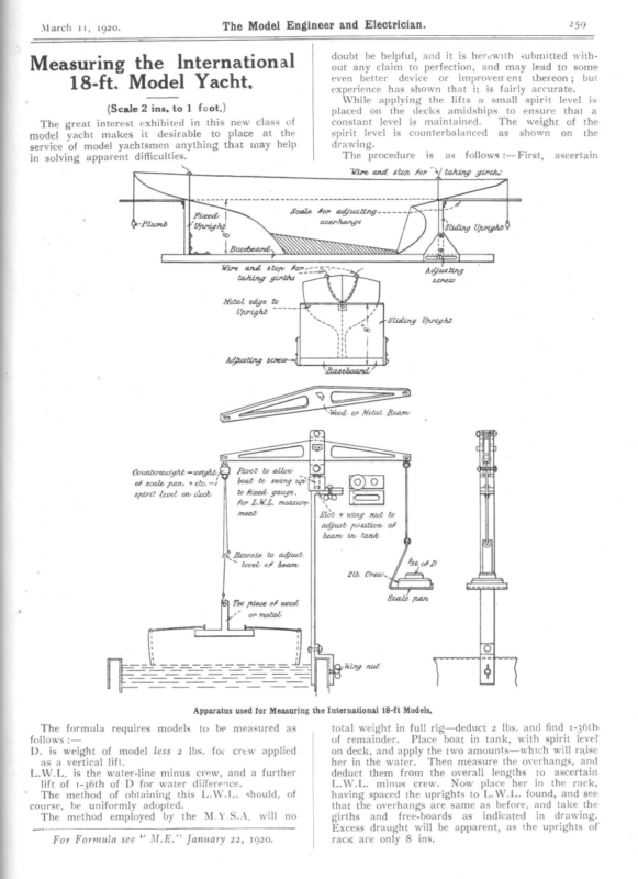
March 11, The Model Engineer and Electrician. 1920. Measuring the International 259 doubt be helpful, and it is herewith submitted without any claim to perfection, and may lead to some even better device or improvement thereon; but experience has shown that it is fairly accurate. 18-ft. Model Yacht. While applying the lifts a small spirit level is placed on the decks amidships to ensure that a (Scale 2 ins, to 1 fcot,) The great interest exhibited in this new class of model yacht makes it desirable to place at the service of model yachtsmen anything that may help in solving apparent difficulties. constant level is maintained. The weight of the spirit level is counterbalanced as shown on_ the drawing. The procedure is as follows :—First, ascertain Wire and ston for) taking girth> cosrns prcasnanenaweeian> f -Plumb Pt L | Scale for adjusiing—— <7 7H Uris Ae overhangs WA | pascboand:, { lay i ua Wire j Upright =0=) and stop for---5->~~- Adjusting taking girths sonew Heal edge lo Upwighe ~~~ SS | a“ stating: trom A Sliding Upright Counterwetght = weight, of scale pan, + ec. -) [oid spirit level or heck Apparatus used for Measuring the International 18-ft Models, The formula requires models to be measured as follows :— D. is weight of model less 2 lbs. for as a vertical L.W.L,. is the lift of 1-36th The method crew applied lift. water-line minus crew, and a further of D for water difference. of obtaining this L.W.L. should, of course, be uniformly adopted. The method employed by the For Formula see M.E.”’ M.Y.S.A. will January y 22, 2 , 1920. 19 no total weight in full rig—deduct 2 lbs. and find 1-36th of remainder. Place boat in tank, with spirit level on deck, and apply the two amounts—which will raise her in the water. Then measure the overhangs, and deduct them from the overall lengths to ascertain L.W.L. minus crew. Now place her in the rack, having spaced the uprights to L.W.L. found, and see that the overhangs are same as before, and take the girths and free-boards as indicated in drawing. Excess draught will be apparent, as the uprights of rack are only 8 ins.
522 The Model Engineer and Electrician, – ‘tangent of an angle of 813 degrees (taken from any ‘table of tangents or from a table of cone angles) and is the angle of rake of the worm thread to the vaxis of the worm. The worm wheel axis stands normally at right angles to the worm shaft, hence it is only set over the difference between 813 and go, or 83 degrees as described. Referring to Fig. 1, it will be noticed that the “cutter is run in the lathe on an arbor, which is chucked, but supported by the tail centre. Assuming the cutter is running true, this method is perhaps rather better than by driver and carrier on a live centre, although that mounting will be all in order. Referring to the size cutter. It will be best to ‘choose the nearest regular size, erring, if anything, on the large size. The apparent pitch or tooth pitch of the wheel is 1-6th in. or .167, say. The nearest diametral pitch to this is 19, which is .1653 circular. “This, however, is cutting it too fine; say, use 18 D.P. having a circular pitch of .174, but we used 16 D.P., which is .196, and it answered fairly well, “excepting that cutter was rather too large in diameter. No. 6 shape is correct, as it will cut from 17 to 20 teeth, and it is important that the hob will gear before starting to hob the wheel. The. method described is regular workshop practice, excepting that the gashing is usually done son a Universal milling machine. In this case the workman knows from practice what cutter to use .and exactly how far to gash a wheel. When only -one wheel is required, however, there is a better, but much longer method of gashing a wheel, involving the use of a taper hob in a screw-cutting lathe. ‘This has been described years ago in the M.E., but further reference will be made on this matter in ‘future notes on this almost inexhaustable subject of wheel cutting. Real Yachts and Model Yachts. By C. STansFIELD Hicks, Author of ‘‘ The Merchant Service,’’ Boats and Canoes,”’ etc. MEMORABLE year in yachting ‘‘ Yachts, June 3, 1920. ‘L.W.L. xX 6 ft. 6 ins. beam. I saw one at Wivem hoe 60 ft. x 6 ft. beam, but she was never launched as a racer, as the rule came to an end. Thistle, afterwards Meteor, was cut away much as Jullomer forward, and Mr. Watson handsomely acknowledge@ that this was done from data obtained Bentall’s experiment. Thistle, though fast, a success to windward, being outpointed by defender; Jullanar, on the other hand, was a by Me was net the Cap splend vessel Americg close hauled. The lesson which TT” See Fig. 1.—-Straight Stem Cutter, 94 Rule. gave in 1854 had not been learnt, and the bad it» America was fluence of the old Rule continued. a craft of light displacement and large over water body, while our boats were of heavy displacemes=. The America long hollow bow had been copied TM many cases, but the English midship sections @ heavy displacement remained practically unaltered: Fig. 2.—Sheer Outline of B “Jullanar.’”’ An iron yacht, Mosquito, built in 1848, had a mie ship section much like America, and also a long” hollow bow. Her straight stem, however, prevented the extreme flare forward so pronounced a feature the America’s bow, and she had less beam in pew portion and heavier displacement. – The 94 Ret Hewett, o® Mr. 1897, about altered being amateur, in Buttercup, 1880, was one of the first take advantage of the new rule, whereby lenge® was measured on the L.W.L. was that of A 1875, for tt was then that Jullanar was brought out by an amateur, and originated an :absolutely new departure in the form of yachts. Before 1878 all the celebrated yachts from the old Arrow to the Bloodhound, Fiona, Irex, May, Vanduara and Formosa, as well as the America Cup challenger Genesta were all straight stem boats with more or less the regular orthodox sheer plan of the type given, Fig.°1. Mr. Bentall, in Jullanar, cut away all the deadwood possible, leaving convex body, lines in bow and stern, and dropping the keel amidships to secure the wequisite lateral resistance. Among the yacht hands tailing from the district, Brightlingsea, Tollesbury, etc., she was generally known as the ‘‘ Mussel Shell.’? There is a very good model of this epochmaking yacht in South Kensington Museum, also of America. The curious stern of Jullanar was the outcome of the racing rule of the time, as was also the depth, which under that rule was untaxed. Later on Mr. Bentall built the first fin keel boat, Evolution. She ‘was a 1o-tonner, and one of the most extreme of the many extreme boats of the time, being 51 ft. a Fig. 4.—American type Pilot Schooner, culminating in “America”? Water line should be shown slightly lower. Fig, 3—The fut fin keel boat “Evolution.” I remember seeing her when she first came and all on board thought her a_ small sch rigged as a cutter. She was the first cutter seen § the London river with a clipper bow. Butter was 42 ft. L.W.L., beam 11 ft., draft 8 ft., placement 22 tons, rating 1o tons, lead 14 mast 30 ft. deck to hounds, masthead 6 ft., to 29 ft., boom 4o ft., gaff 28, bowsprit outboard 19 © S.A. 23400 ft,
The Model Engineer and Electrician, June 3, 1920. (L + B)? x B In 1882 a new Rule came in force ————————— 1730 monly called the 1730 Rule under which length depth were used at the expense of beam even re than under the 94 Rule. 523 The first great departure under this rule was with the advent in this country of the half-rater Wee Win, in 1892. Herreshoff, in his usual way, eviscerated the rule and took those elements and those only that counted. A canoe body to run over the water—the exact amount of lateral resistance needed for the S.A. in the form of a metal fin—the lead disposed in the most effective form at the lowest point in the forms _ ee = el Fig. 6.—Sheer Outline of “ Buttercup.’”” of a torpedo halved and bolted on the bottom of the fin. Fig. 5.—English Cutter in the fifties, A more extreme example produced by the 1730 le was Oona, unfortunately lost off Malahide. She 5 tons, 33 ft. L.W.L., beam 5.6, draft 8, 12 tons lacement and 2,000 ft. S.A. When the L.S.A. rule came in about 1886, beam \) Such was the Wee Win. Under this rating rule how much in principle have: we advanced since then? This was the boat andi the only type that was the correct solution of the rule to produce speed. Wet and uncomfortable, but fast. In real yachts, even small ones, the English designer likes to get in a little more displacement, a little more beauty of design, and to make a sweeter curve at the junction of the body and the appendage, fin, keel, or whatever it is called, but these nice: curves mean displacement, and that, too, where it is. not wanted—I mean for speed, and Herreshoff’s design has no other end. The 1-raters had practically the same form of fim as the model rater to-day, but had no fin aft, using: instead a metal rudder with a stem working through: 7.—“ Oona,’’ English Yacht of about 1885, produced by the 1730 Rule. Fig. 8.—Sheer Outline of “Creole’’ immediateiy taken advantage of in the small es, and with a shallow body long overhang could given, which was not the case in the rule that uced the clipper bow. The early boats of the small classes under this 1890. Built under the L. & S.A. Rule. For extreme speed with small sail area there has nothing to touch the form then introduced, and which is now continued in the model raters. These boats are machines, that must be allowed— still they are most effective so far as speed is conbeen O Fig. 9.—Sheer Outline of “ Wee Win.” were rigged with a big lug and a small jib, and e a handful in a breeze, at all events compared the deeper craft previously produced, which e very sweet and casy in a seaway. he design of some well-known large yachts built ler the L. and S.A. rule would rather astonish model builder under the sarne rule. ance, Queen Mab or Creole. Take, for Fig. 10.—Sheer Outline of the early small Rater. cerned, combining easy form and lightness of hull, effective lateral resistance, low ballast, and small and easily managed sails. For real craft they are wet, and have no accommodation, but that does not apply to models. While we must concede their speed, there remains the fact
that a certain number of even model yachtsmen have a liking for something more wholesome and sea~ worthy, something that partakes more of the nature and carries with it something of the romance of real sea craft—that, fast for its type, is a home to its crew and is able to battle with and overcome the elements even in their greatest fury. To drop anchor in a snug harbour after a wild night and a hard thrash against opposing wind and sea is a delightful experience in real yachting, and the repose so earned has an enjoyment which is very real. So in a measure is the interest which some model men are inclined to take in a model built from the lines of such an able and seaworthy craft. The same kind of difference is shown in steam and power. Some. Crop in deck not to exceed 3 in. Sheer. A fair sheer must be given, and for ¢ purpose freeboard is untaxed, except at lowest poimTM, where it must not exceed 24 ins. Beam, untaxed, as in some designs it might & used with advantage. Cabin space. The special point in the design & that it has to contain a cuboid behind the mast 12 ins. long, 6 ins. wide, and 5 ins. high. No fin or bulb keel to be allowed. Under lower sail the model must Rating. measure up as a to-rater, under the rule Deck Line of Yacht at 241%. go in for the racer pure and simple, which scoots up the lake in a few seconds, flying over the water in a cascade of foam and spray. Others prefer the model of the real steamer with all its fittings, which with less speed presents a perfect picture of a real liner or vessel of war. It was with this knowledge that I mentioned to the Editor an idea for a r1o-rater fast cabin cruiser, to be taken as nearly as possible ENGINEER. Freeboaré Midships dS § Cuboid RN from an able small seagoing yacht, worked out on a to-rater basis and without any mathematical formula—in fact as simple as a rater. The Editor accepted the idea in the most sportsmanlike way, and an arrangement has been made by which the Editor of the Yachting Monthly will organise a competition for the best designs for-such a model, based on the data obtained from the actual dimensions, sail area and weights of an existing yacht of about 16 tons. The prize of £5 is being put up by Tue MopeL 1920. June 3, ? & WL. 5 { 3 Ft. kK Fast Cabin Cruiser Competition (10-rater). The idea of this suggested class is to get a design that, while being suitable for a real yacht, can with certain restrictions be successfully produced as ‘a model on the scale of 1 in. to a foot. It is obvious that on the:design 6 ft. headroom in a real yacht could be easily given by cabin top or increased freeboard. The midship section of an actual yacht of ee | Wood Keel (Yacht) (Yacht) ad Keel Le fH 6Ft. Lead 4 Fig. 11.—Two Rough Sheers Plans: Real Yacht shown in Outline ; and Model Design containing Cuboid in Black. about 16 tons yacht measurement is given. This vessel has practically 6 ft. headroom, and the general idea is based on this boat of good seagoing qualities. A designer, however, is free section, but the design must going craft. Cut down to 5 the cuboid, this yacht works an approximate displacement to use any midship produce a good seaft. headroom, as in out proportionally at of 19 lbs. which is distributed for the model, about 5 lbs. hull, 2 Ibs. spars and sails, and 12 lbs. lead—giving in a good design ample stability to carry the requisite sail the in This distribution will appear area. ““ Yachting Monthly’s ’’ particulars for designers. Dimensions not to be exceeded for the model :— 1 1 J 7 — 8Ft. Fig. 12.—Midship Section of Real Yacht. LWL x SA —_—_—_—— = Rating. 6,000 Mainsail not to exceed 75 per cent. of lower canvas. Rating, only calculated on lower canvas. This is for model racing, but topsails can provided for cruising, not exceeding 25 per cent lower sail area. L.O.A. §4 inches. The above is simply a suggestion. So long as i cuboid is retained other dimensions might be alteret Draught 6 ft.—for model two feet extra, 8 ins. Displacement of model not to exceed 19 Ibs. Model yachtsmen will be glad to know that i editor of the Yachting Monthly is kindly giving: Water line 37.4 inches. ST The Model Engineer and Electrician. 524 if generally desired. |
June 3, The Model Engineer and Electrician, 19207 special attention to this competition, and I trust it may be of service in bringing new interest into the Sport. What I think specially desirable is that new builders should come forward. I am sure there must be a large number of readers of THE MOopeEL ENGINEER well able to build this model. It is not more difficult than building an ordinary rater, and there will be no trouble as to design, as blue prints of the winning design, scale 1 in. to 1 foot, will be supplied at a small charge by THE MopEL ENGINEER. As the editor of the Yachting Monthly said, “We will find the designers, let THx MopeL ENGINEER find the builders.”’ The greatest departure from all previous yachts in design was made by an amateur, Mr. Bentall, in jJullanar. The American shipbuilders who built the famous Yankee clippers believed in and experimented with models. When one thinks of the expense of trying new forms in real vessels, and the small expense of models it is obvious that much might be done in this direction, particularly by experiments untrammelied by rules which cnly pro- duce one type. Note—MEasurEMENT.—It this design was built to, measurements of cabin space would be made by depth rods passed through four small holes in the deck ; they could afterwards be plugged up. No timber or rib should be left in the wake of such dimension, so that the rod can come on to the skin of the boat. The other measurements are those of an ordinary to-rater with draft restricted to 8 inches, the lower sails only being used as a io-rater. 1,600 S.A. x 3774 water line. = 9°97 Rating. 6,000 For the present I have not dealt with any of the two-masted vessels: lowances for the this I propose to discuss later. Practical Letters from our Readers. ‘““The Model Engineer ’’ Telescope. To tHe Epitor oF The Model Engineer. Dear Sir,—In a recent issue of the M.E., Mr. eath concludes a valuable series of articles on the mstruction of a small refracting telescope. He omises to give further directions for the conuction of accessories, alternative mountings, etc., r this instrument. No doubt for all-round use for th terrestrial and celestial objects the instrument scribed is quite the best and likely to appeal to the eatest number of readers. I should be interested know, however, whether a reflecting telescope, as stinct from a refractor, would be of sufficient meral interest to warrant the publication of a scriptive article—perhaps from the pen of Mr. eath—such as the one just completed. Short icles relating to astronomical reflectors made by ders have appeared in the M.E. on one or two asions since 1908, but. so far as I remember the thors have been too modest regarding their ievements to give much enlightenment to others o might be thinking of constructing similar . truments. The light-grasping power of a reflecting telescope said to be somewhat inferior to that of a refractor 525 of equal size, but it has the enormous advantage for astronomical purposes of giving an image absolutely free from chromatic aberration, whereas the most carefully corrected—and correspondingly expensive —object glass of a refractory telescope can never more than approximate to this ideal. But what I venture to think would appeal to many contemplating the construction of a telescope is the reduced cost of the glasses—which they would, no doubt, purchase—of the reflector as compared with the refracting instrument. From a book by a rather famous professional optician I understand that a reflecting telescope with a §-in. speculum can be made as efficient as a 43-in. refractor at one-third the cost of the latter. If this be so, I consider it a very strong point in favour of the reflector, and I venture an to suggest, Sir, that you consider whether article dealing with the construction of such an instrument is called for. The mounting, as already described 3-in. telescope, wuold probably do for for the the reflector or perhaps Mr. Heath would describe an equatorial stand suitable for cither instrument.— Yours truly, C. BLAzpDELL. Curdridge, Hants. Running Solid Fuel Locos. To tHe Eprror or The Model Engineer. Sir,—No doubt a great many of your readers will much appreciate the recent articles on model solid fuel boilers. Personally I have given a lot of time to the study of this subject in regard to the smallest gauge, the idea being to find the smallest space in which a charcoal fire may be made to burn with satisfactory results. From various experiments made with solid fuel in Gauge O, I am convinced that for realism and safety there is nothing to beat it. For those who run their locomotives for the sole purpose of giving movement to a model railway perhaps methylated spirit is the most convenient method of firing, but to the model engineer whose interests are bound up in the locomotive and who aspires to become the driver of a minature railway engine, he cannot do better than adopt charcoal firing. Its added attractions of smoke and sparks, and a fire which answers the least touch of the blower, makes a properly designed solid fuel boiler hard to equal.—I am, yours faithfully, ApRIAN F. BRowuGH. An Ornamental Turners’ Society. To tHe Epiror or The Model Engineer. Dear Sir,—In your issue of March 4th last a correspondent suggests the formation of an ornamental turners’ society and invites criticism. In the first place, I do not think such a society would ever be as popular as, say, the model engineering, model yachting, or wireless clubs at present running. Then, again, its members would probably be very widely scattered, making the cost of meeting prohibitive in these days to the humbler members, while the post-war cost of the rare woods and ivory generally used in the higher branches of the art would be out of all proportion to the value of the finished article. And how about the post-war price of some of the more elaborate pieces of apparatus? Also those who think of taking up this work should remember that the practical utility of the finished work is very small, the finest and most delicate pieces shown by most writers on the subject, from


