- Vane Steering for Models (by H. Hamley Tregoning). Following the display of a prototype at the Model Engineer Exhibition in January 1923, Tregoning detailed the construction and principles of this “departure from generally accepted methods.”
- Scientific Principle: The system harnesses a vane (or “stiffened flag”) mounted at the masthead and geared to the rudder. When the boat swerves from its course, the wind hits the side of the vane, forcing it to rotate. This movement is transmitted to the rudder in the opposite direction, steering the boat back to its original heading until the vane is again “streaming” directly with the wind.
- Unique Advantages:
- All-Weather Performance: Unlike the popular Braine gear, which typically must be disconnected for close-hauled sailing, vane steering remains efficient on all points of sail. It allows models to be “pinched” closer than the standard four points off the wind without falling into irons.
- Proportional Correction: The gear provides gentle, delicate corrections. If the boat swerves slightly, the helm response is equally slight, preventing the “over-correction” common in rubber-cord systems.
- Power Boat Application: Tregoning suggests the gear could even steer power models in a breeze, provided the boat’s speed does not exceed the true wind speed, thereby countering the natural tendency of vessels to turn head-to-wind.
- Design Freedom: Because the gear can manage both “lee” and “weather” helm automatically, designers can take more liberties with the center of effort in the sail plan.

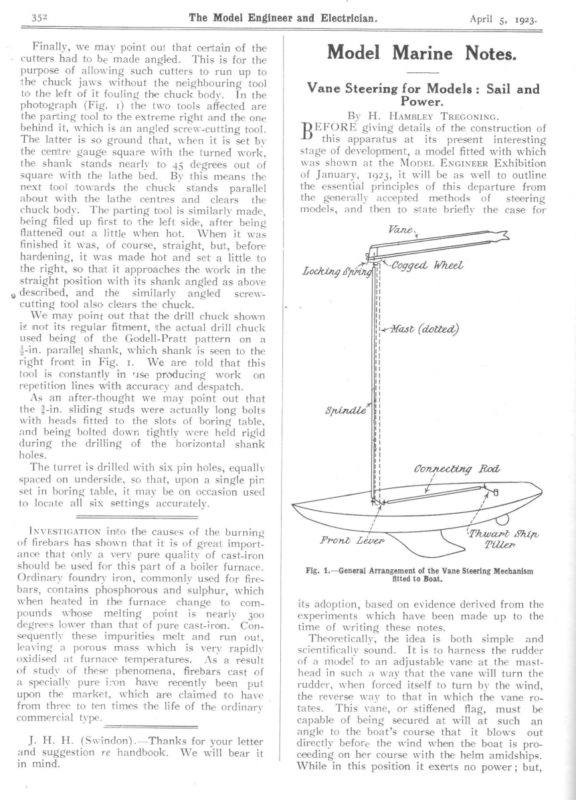
352 The Model Engineer and Electrician. Finally, we may point out that certain of the cutters had to be made angled. This is for the purpose of allowing such cutters to run up to the chuck jaws without the neighbouring to the left of it fouling the chuck body. In photograph (Fig. 1) the two tools affected the parting tool to the extreme right and the tool the are one behind it, which is an angled screw-cutting tool. The latter is so ground that, when it is set by the centre gauge square with the turned work, the shank stands nearly to 45 degrees out of square with the lathe bed. By this means the next tool towards the chuck stands parallel about with the lathe centres and clears the chuck body. The parting tool is similarly made, being filed up first to the left side, after being April 5, 1923. Model Marine Notes. Vane Steering for Models: Sail and Power. By H. Hampiey TrEGONING. BEORE giving details of the construction of this apparatus at its present interesting stage of development, a model fitted with which was shown at the MopeL ENGINEER Exhibition of January, 1923, it will be as well to outline the essential principles of this departure from the generally accepted methods of _ steering models, and then to state briefly the case for flattened out a little when hot. When it was finished it was, of course, straight, but, before hardening, it was made hot and set a little to the right, so that it approaches the work in the straight position with its shank angled as above described, and the similarly angled screwcutting tool also clears the chuck. We may point out that the drill chuck shown ig not its regular fitment, ‘the actual drill chuck used being of the Godell-Pratt pattern on a 3-in. paralle] shank, which shank is seen to the right front in Fig. 1. We are told that this tool is constantly in “ise producing work on repetition lines with accuracy and despatch. As an after-thought we may point out that the 3-in. sliding studs were actually long bolts with heads fitted to the slots of boring table, and being bolted down tightly were held rigid during the drilling of the horizontal shank holes. The turret is drilled with six pin holes, equally spaced on underside, so that, upon a single pin set in boring table, it may be on occasion used to locate all six settings accurately. INVESTIGATION inito the causes of the burning of firebars has shown that it is of great import- ance that only a very pure quality of cast-iron should be used for this part of a boiler furnace. Ordinary foundry iron, commonly used for firebars, contains phosphorous and sulphur, which when heated in the furnace change to compounds whose melting point is nearly degrees lower than that of pure cast-iron. sequently leaving these impurities melt and run 300 Conout, a porous mass which is very rapidly oxidised at furnace temperatures. As a result of study of these phenomena, firebars cast of a specially pure ivon have recently been put upon the market, which are claimed ito have from three to ten times the life of the ordinary commercial type. J. H. H. (Swindon).—Thanks for your letter and suggestion re handbook. We will bear it in mind. Fig. 1.—General Arrangement of the Vane Steering Mechanism fitted to Boat. its adoption, based on evidence derived from the which have been made up to the time of writing these notes. experiments Theoretically, the idea is scientifically sound. It is to of a model to an adjustable head in such a way that the both simple and harness the rudder vane at the mastvane will turn the rudder, when forced itself to turn by the wind, the reverse way to that in which the vane rotates. This vane, or stiffened flag, must be capable of being secured at will at such an angle to the boat’s course that it blows out directly before the wind when the boat is proceeding on her course with the helm amidships. While in this position it exerts no power; but,
April 5, 1923. The Model Engineer and Electrician. immediately the boat swerves, -bringing a current of wind to bear on one side or the other of the vane, the latter will tend to resume its original position with regard to the wind, and, in doing this, brings the rudder round in such a way that the boat is steered back to its proper course; where the vane resumes its original angle to the boat’s course, and the rudder is steadied. Projecting guides for @ Brass Shoe with Hole es ~ t Wire Locking Spring — Bult “on j ‘ © of amma is that-a single-sailed model can be sailed satis. factorily, There is littie doubt that such a ric is advantageous to windward. It may be la down as a certainty, in the case of a manned tageous is – of Vane | perienced men when it would be very usefu Then, with this means of cont: designer may begin to take liberties with h centres of effort, knowing that he can lee helm as well as weather. An impor: point in connection with this complete cont: indeed. boat, that the smaller the boat ithe more advan- iy Locking Clipy View of Butt | 353 Ribbon ‘logged Wheel = Top Bearer the undivided sail-plan. If this ruk holds in the case of models—and I see no reason why it should not—vane steering is indeed worthy the attention of the model’ yacht designer. Secondly, the vane is equally efficient, equally delicate and equally powerful in correcting deflections on either side of the correct course, in any direction, and under all circumstances. There can be no such thing as over-correction, and under-correction is only possible when too smali a vane is used. The delicate operations of altering the tension of rubber cords, lengthening and shortening levers and sheets, involving endless, experiments and occasionally a bad mistake, are all done away with, and ithe whole question fines down to judging correctly the direction of the wind in relation to the boat’s course, and handling the sheets properly, The vane’s action is governed by the direction of the wind. If the boat swerves slightly, the helm given to correct it is slight and gentle. With front lever and tiller of equal length (Fig. 1), the correcting angle taken by the rudder should be about equal to the angle of the boat’s deviation from her course. FE Fig. 2.—Detallof s Vane Steering Mechanism. Thirdly, this gear is capable of being used to It may be asked by those familiar with the wonderfully accurate steering that can be accomplished with the gears (or rather gear, for there is only one worth considering—the Braine), what particular advantages has this new gear, un- familiar to them in principle and practice, over others? I will try to state the case for it as fairly and moderately as I can. Firstly, it is equaily efficient in correcting deviations on all points of sailing. This is a unique claim to make for a model steering gear, but fully justified in this case. Every other gear has to be thrown out of action when it comes to real close-hauled sailing, but the model exhibited in January was pinched up to a course considerably closer than the usual four points off the wind a few days ago, and held a steady course at an angle which would, in the great majority of cases, have meant shivering in irons most of the time. I am far from asserting that the power to accomplish such a feat is of great practical use in model racing, but conditions will suggest themselves to ex- steer a power model at any time when a breeze is blowing on the course, unless, with a following wind, the boat is as fast, or faster, than the wind. I know little of power models practically, but it is a scientific fact that all boats in motion tend to turn head to wind. The use of this gear will prevent this, and a strong and steady breeze will be as good as a man at the helm. It must be borne in mind, however, than the vane must be set for the apparent breeze, which, in ‘the case more of a fast ahead model, than stationary object. blows apparently from the true breeze as felt by a This, briefly outlined, is the case for vane Experiments have been made, not only with the 18-footer exhibited at the Horticultural Hall, which was specially selected steering. as a hard boat to steer, but with a model to-rater built to the well-known lines of Mr. Daniell’s XPDNC. This beautifully balanced model gave excellent results at the first trial, sailing long distances—about half a mile—on a large sheet of water in practically straight lines in any required direction, except, of course, the
The Model Engineer and Electrician. 354 45 degrees, more or less, on either side of the wind’s eye, which is closed to direct progress by any sailing craft. The vane gave results of equal merit on ali these courses, I will close by giving such details of construction as will enable anyone to fit this gear to any sailing or power craft where the’ mastapproximately clear of other spars. The reader must bear in mind that all parts are simplified to suit the use of limited tools and head rises materials by an amateur workman. But any- one who foliows the same methods will find the results strong, light and efficient. They have also the merit of being inexpensive. First the vane itself. This I make long and narrow, 18 in. Bauduin, of to 20 in. by 2 the Royal in. Dutch Vice-Admiral Navy, who has April 5, 1923. two bearers projecting obliquely forward from the mast at top and bottom to avoid touching fore-stay (Figs. 1 and 2). The spindle itself may be made of wood, wire, or inetal tube. Mine is of wood, with top and bottom ends of brass wire, but this was merely a matter of convenience and ease of construction with available tools and materials. The wires are flattened at their ends and driven into the ends of the wooden rod, which has first been whipped with stout thread. If considered necessary, a small hole may be drilled through flattened wire and wooden spindle, and the whole riveted together with a brass or copper na‘l. The lower piece of wire is tapered toa point, which may rest on a brass thrust-plate on the deck. This bears the of the whole fitment and gives the minimum of friction. weight been experimenting independently with a similar gear for some years, uses a short, almost square vane, which he finds efficient and satisfactory. portion of the spindle, is now soldered a brass sideration, cogged wheel (Fig. 2) of 32, 40, 48, 56, or 64 teeth. Sixty-four is the ideal number, as it But I have retained the long one, after due confor the sake of the presumably greater sensitiveness to small changes of direction, and, therefore, probably finer steering. The framework is of three pieces of pine, shaped, when joined, like a hair-pin (Fig. 1). Top and bottom pieces are about 3-16th in. square, tapered to 3-32nd in. at the ends. The Fig. 3.—The Cogged Wheel Lettered and Painted. butt (Fig. 2) is about 3-16th in. by 3 in. I generally saw the top and bottom frames open at the butt (see Fig. 2), and insert the upright portion in the opening. The three parts are then secured by giueing and pinning (3-in. copper pins). This frame has a piece otf silk ribbon (colour to taste) laced into it with cotton or thread. This is finished off with a free inch or two, The butt of the vane is now shod with a brass plate (Fig. 2), which projects level with the cogs of the wheel below, and has a slot sawn into it as a guide for the wire locking spring (Fig. 2). Into the plate and extending up into the butt of the vane is now drilled a hole to receive the top end of the steering spindle, which is the centre of the vane’s rotation, when the adjustment is being made, by dropping the wire locking spring into a cog of the toothed wheel below. The spindle above mentioned forms the first stage of ‘the vane’s connection with the rudder. This may be piaced inside the mast, if hollow ; or, if the mast is solid, the spindle revolves on Just clear above the mast-head, on makes half-point possible in the (5% degrees) adjustment of the wire differences the vane. The vane can now be pushed down on ‘the projection (Fig. 2, dotted), and locked between any two cogs at will by means of the brass wire locking spring, as above described. Fig. gives a method of painting and numbering the top of the cogged wheel, painting the port side red and the starboard green. The arrow shows ‘the boat’s direction with the helm amidships. It is important to note that star points and arrow points must end in slots, not cogs. At the bottom of the spindie, near the deck, a wire rod projects, horizontally, about three inches, fitted as shown (Fig. 2), with a shoulder and nut. I improvised this portion of the gear with a cycle spoke nipple sawn in two, the head forming the shoulder and the rest the nut. Its proper position is at right angles, or thereabouts, to the boat’s length (Fig. 1) Between the shoulder and nut is fitted the end of the connecting rod (Fig. 1). The rudder, ordinary if yoke or not already quadrant, fitted when it with is the only necessary to pivot the rod to the extreme hole in yoke on the opposite side of the boat from that on which the spindle lever projects, has to be fitted with a thwart-ship tiller, which is an exact replica of the spindle lever, but fastened to the rudder stem on the opposite side from the spindle lever, as above. The connecting wire, metal rod itself may be made tube, or of wood and wire, same way as the upright steering spindle. of in the This is fitted over the projecting portions of lever and tiller, and the nuts screwed on. In the case of a yoke being already fitted, it is pivoted into it by means of the usual bayonet-shaped hook, just like those on the already existing steering sheets.
‘gz61 “gt yore Mr, Weaver and his Celebrated Pipe. NEW YORK, GIVING A GLIMPSE OF FLUSHING BAY SOME VIEWS FROM MR. GEORGE BENDER,EAGLE CUP RACE LAST YEAR, AT THE TIME OF THE [see page 305 £o0€ Turning the Mark. Close Quarters. Watching the Boats Get Ready.. For description] ‘moJAoy AAQUTMOVW URI pus qgoulsugq [epom PL Getting Ready. Mr, Weaver holding his boat high in the air.
December 16, 1926. The Pz 9 alo \ ah ene ae i a and Light R® Machinery SS \ a Review. 589 * \ \ al | | Engineer “2 | = Model ii as\ —\ i a : | —_— [oe el DESIGN FOR L.O;A. Plans . mesi LW ese Draught is: Beam Se BIG DISPLACEMENT. For description see page 593. Body Plan. ee ees wes es «=O TS, «6420 Epes. ges | aes ~ Lcd Sins, «< sw: eee ... eee vee ... ... ... 0 0. we) eee S.A. see see Displacement Lead... 10-RATER ‘‘ ALLEGRO.” Dimensions. wee eee, ca 9:0 dis. ©: 1426 88q. ins, 24.4 Ibs. 15.5 Ibs.


