- Model Yacht Designing: The Keel (by “Kappa”). Writing on August 11, “Kappa” explored the hydrodynamics of the keel, using a clever “orange pip” analogy to explain how a boat moves against the wind.
- The “Squeeze” Effect: He likened a yacht to an orange pip squeezed between a finger (wind pressure on sails) and a thumb (lateral resistance of the keel in water). Because water is 850 times heavier than air, the keel provides the necessary “grip” for the boat to “slip” forward rather than simply drifting to leeward.
- Slippery vs. Gritty:
- Light Weather: The boat is “slippery” like a fresh pip. Resistance is low, allowing for tighter sail sheeting angles.
- Hard Wind: The boat encounters more resistance and behaves like a “dried pea.” In these conditions, the sails must be eased to a wider angle to prevent the boat from becoming “dead and lifeless.”
- Keel Duties: The keel must provide maximum sail-carrying power (leverage) and lateral resistance without disrupting the hull balance or interfering with the boat’s ability to “respond to the action of the sails” (maneuverability).

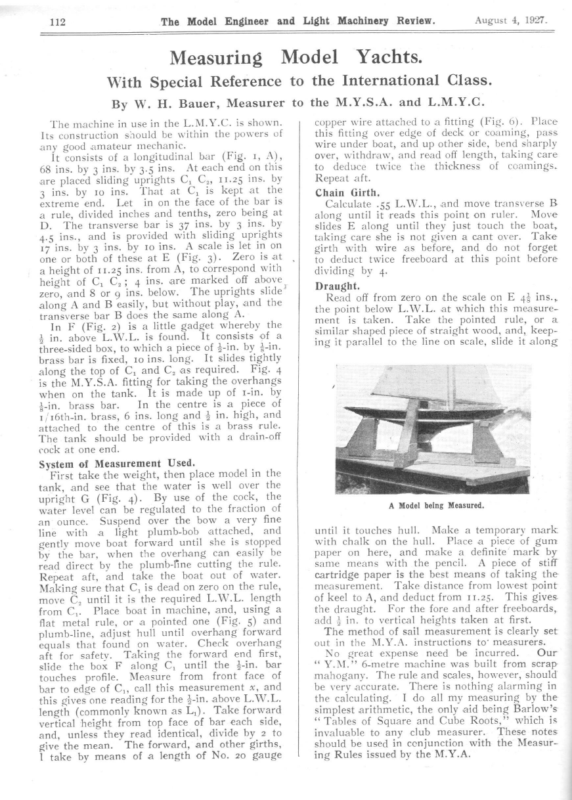
The Model Engineer and Light Machinery Review. 112 Measuring Model August 4, 1927. Yachts. With Special Reference to the International Class. By W. H. Bauer, Measurer to the M.Y.S.A. and L.M.Y.C. The machine in use in the L.M.Y.C. is shown. Its construction should be within the powers of any good amateur mechanic. It consists of a longitudinal bar (Fig. 1, A), 68 ins. by 3 ins. by 3.5 ins. At each end on this are placed sliding uprights C, C,, 11.25 ins. by 3 ins. by 10 ins. That at C, is kept at the extreme end. Let in on the face of the bar is a rule, divided inches and tenths, zero being at D. The transverse bar is 37 ins. by 3 ins. by 4.5 ins., and is provided with sliding uprights 17 ins. by 3 ins. by 10 ins. A scale is let in on one or both of these at E (Fig. 3). Zero is at a height of 11.25 ins. from A, to correspond with height of C, C,; 4 ins. are marked off above| zero, and 8 or 9 ins. below. The uprights slide” along A and B easily, but without play, and the transverse bar B does the same along A. In F (Fig. 2) is a little gadget whereby the 2 in. above L.W.L. is found. It consists of a three-sided box, to which a piece of $-in. by 4-in. copper wire attached to a fitting (Fig. 6). Place this fitting over edge of deck or coaming, pass wire under boat, and up other side, bend sharply over, withdraw, and read off length, taking care to deduce twice the thickness of coamings. Repeat aft. Chain Girth. Calculate .55 L.W.L., and move transverse B along until it reads this point on ruler. Move slides E along until they just touch the boat, taking care she is not given a cant over. Take girth with wire as before, and do not forget to deduct twice freeboard at this point before dividing by 4. Draught. Read off from zero on the scale on E 4} ins., the point below L.W.L. at which this measurement is taken. Take the pointed rule, or a similar shaped piece of straight wood, and, keep- ing it parallel to the line on scale, slide it along brass bar is fixed, ro ins. long. It slides tightly along the top of C, and C, as required. Fig. 4 is the M.Y.S.A. fitting for taking the overhangs when on the tank. It is made up of 1-in. by In the centre is a piece of tin. brass bar. 1/16th-in. brass, 6 ins. long and 3 in. high, and attached to the centre of this is a brass rule. The tank should be provided with a drain-off cock at one end. System of Measurement Used. First take the weight, then place model in the tank, and see that the water is well over the upright G (Fig. 4). By use of the cock, the water level can be regulated to the fraction of an ounce. Suspend over the bow a very fine line with a light plumb-bob attached, and gently move boat forward until she is stopped by the bar, when the overhang can easily be read direct by the plumb-fine cutting the rule. Repeat aft, and take the boat out of water. Making sure that C, is dead on zero on the rule, move C, until it is the required L.W.L. length from C,. Place boat in machine, and, using a flat metal rule, or a pointed one (Fig. 5) and plumb-line, adjust hull until! overhang forward equals that found on water. Check overhang aft for safety. Taking the forward end first, slide the box F along C, until the 3-in. bar touches profile. Measure from front face of bar to edge of C,, call this measurement x, and this gives one reading for the 3-in. above L.W.L. length (commonly known as L,). Take forward vertical height from top face of bar each side, and, unless they read identical, divide by 2 to give the mean. The forward, and other girths, 1 take by means of a length of No. 20 gauge A Model being Measured. until it touches hull. Make a temporary mark with chalk on the hull. Place a piece of gum paper on here, and make a definite mark by same means with the pencil. A piece of stiff cartridge paper is the best means of taking the measurement. Take distance from lowest point of keel to A, and deduct from 11.25. This gives. the draught. For the fore and after freeboards, add 3 in. to vertical heights taken at first. The method of sail measurement is clearly set out in the M.Y.A. instructions to’ measurers. No great expense need be incurred. Our “Y.M.”’ 6-metre machine was built from scrap mahogany. The rule and scales, however, should be very accurate. There is nothing alarming in the calculating. I do all my measuring by the simplest arithmetic, the only aid being Barlow’s “Tables of Square and Cube Roots,’’ which is invaluable to any club measurer. These notes should be used in conjunction with the Measuring Rules issued by the M.Y.A.
113 The Model Engineer and Light Machinery Review. August 4, 1927. Liglrs po lreretereer Fo i 70 PLAN. F;—_| anes a = a er a BA 1A pe) beer \ d iF be t9 GIRTH ,WIRES. #196. |S. . ee ELEVATION. 452 ~F¢ Rule POINTED RULE. S OF APPARATUS USED FOR MEASURING MODEL YACHTS GENERAL ARRANGEMENT AND DETAIL OF THE INTERNATIONAL CLASS.
The Model Engineer and Light Machinery Review. 138 NN WS NX Rew ee NNAATN <= August 11, 1927. SSW SSAA EES Ww Model Yacht Designing. 1l1i—The Keel. By ‘‘ Kappa.”’ The duties of the keel can perhaps be regarded as four in number. It must provide the model with as much sail-carrying power as possible, and it must provide ample lateral resistance from the the water. It must not interfere with hull balance of the model, which rests in the form as indicated in the last article, neither must its length interfere with the free movement of the model in responding to the action of the sails. In order that these duties may be fully appre- ciated, it is advisable to visualise clearly how the model sails against the wind. It will be found be that if she behaves well to windward, she cannot does it but well, reach and run to made follow that a model that runs and reaches well, can be made to do well to windward. Further ‘+t can be stated with a fair amount of confidence that if she is powerful and well balanced on the wind, she will make a good all-round boat. It can be seen clearly what the keel really does by studying the squeezing of an orange pip between the fore finger and thumb of the left hand as in Fig. 1. If AB in Fig. 2 represents the direction of the wind, and CD represents the average angle at which the sails are sheeted, EF being the line of keel, the motion can be reproduced by Figs ‘Ts The forefinger reproduces the total wind pressure and the thumb the lateral resistance. If the model were a balloon with sails and keel, it would simply drift to leeward, as there would be nothing that can be represented by the thumb, but in reality the keel is pressed upon by the water, which happens to be about 850 times heavier than air, and therefore the thumb comes into play. The boat then slips between the two pressures in the same way as the orange pip, except that the model is being continuously squeezed as it projectile—and a very instructive one, too. If travels, whereas the pip escapes and becomes a the pip is fresh and slippery, it can be projected at high speed by a slow movement of finger and the sails and line of keel. Try the effect of a dried pea instead, the angle must be wider and thumb, and by the use of a fine angle between the speed of the projectile slower. Now in light weather the resistance to motion is very small as the model is not travelling in full career, she is relatively more slippery then, and the sails can with advantage be sheeted in to an angle smaller than usual. In a hard wind there is much more resistance to the passage of the boat, she becomes more like the pea, and wider angles are desirable for the sails; in other words, the sheets require easing. Yachts sailing in the same weather as the model may be sailing under light weather conditions with sheets hard home, whereas the model is pressed with the rail well down with sheets eased, and for this reason a model would be killed—dead and lifeless—if the sails were sheeted in as hard as in the case of the yacht. Again, the speed of the pip is governed by the pressure. its way through heavy water which creates too great a resistance. If it were on skates on ice, the skates providing the lateral resistance, then the model too would in all probability sail faster than the wind. Returning to realities, it at once becomes evident that the model must be easy to drive through the water. We shall see later that it eee: F ——~s taterat DOS It has nothing to do with what causes it (i.e., the strength and weight of the wind), and if the resistance to its motion be small, there is nothing to prevent it travelling faster than the wind itself. The model, however, has to force B Y _ “= FO E pressure Fig. 1. Diagrams explaining Hew ee c Fig. 2. Motion of a Sailing Yacht.
August 11, 1927. The Model Engineer and Light Machinery Review. 139 ee Fig. 3.—Diagram showing Why Stern Wave is Formed when Boat is Traveliing Heeled. Fig. 4.—Types of Keels. must be as long as circumstances permit, the of the long keel is that the lead is distributed surface dead smooth, and lines as easy as possible, and yet the hull must be powerful enough to hold the sails up against the wind, in order that the strongest squeeze between finger and thumb may be exerted. ; as low as it can be arranged conveniently, and It is not sufficient to have a large sail area; it is essential that the sail plan be held up against the wind and the power of the boat tells When the model is heeled rail under, as in Fig. 3, the water, after passing under the body of the boat, wants to rise to the surface, and it enormously in windward work, though it is less important in running. The area of the keel must be large enough to deflect a sufficient amount of the heavy water by as small an angle as possible to minimise leeway, and yet provide the essential thumb pressure. The finger pressure is useless thumb pressure and vice versa. without the We then reach two more conditions which have to be aimed at in the design. The resistance to ahead motion must be as small as possible, and the boat must be as stiff as possible. If the keel is too small, it is as though the thumb were cramped and the pip loses not only its speed but direction. If the keel be too large, then there is at once a grave risk of its disturbing the balance of the boat by steering her off or into the wind as she heels. It may appear to be paradoxical and absurd, but the steadiest model may be one with the firmest shelf on which to lean or swing and the shortest keel. In order to appreciate this, swing a square sheet of cardboard by its two upper corners, the cardboard being stretched between the two hands seizing it at the corners. First tie or fix a heavy rule to the bottom edge of the cardboard and swing it like a pendulum. Then attach something of same approximate weight (say, a paper weight) to the centre of the bottom edge. Then swing it and judge for yourself. Does a model swing like this? She may do on the run when she may roll heavily and a concentrated weight will give less disturbing effect to the ends of the boat than a distributed one such as a long bar of lead. “The model then becomes very sensitive, and many owners prefer long keels. The advantage then the squeeze between finger and thumb is as hard as possible. So far very good, but it appears to work well for moderate angles of heel only. does so with sufficient rush to overrun the surface when it reaches it, it continues to rise forming the crest of the stern wave abc. If the streams mno, etc., which are proceeding towards the weather corner of the transom are impeded by after deadwood in the line KL, the effect on the model is as though weather helm had been applied and the model must bear up and sheer off the wind to some extent. Some of the old 80 cm. class of models with unusually long keels were bad offenders in this respect. A slight falling off may be a blessing in disguise in pond sailing, as the wind is usually broken at the weather end of the pond by bushes, spectators, or what not, and the boat is not so apt to be teased and bye. if she is sailing outside a good full The tendency is checked by placing the leading edge of the fin farther forward, but, nevertheless, when sailing upright, the weather helm has vanished, both sides being practically alike, and she fidgets and probably stops by luffing and spilling the headsails. If the keel is long as well, she is longer than she need be in feeling her head and paying-off again. Models of types A and B in Fig. 4 do undoubtedly sail very well when reasonably upright. In fact, with the ballast as low as possible, they should beat the under these conditions. short fin craft The latter have the advantage of being able to put their rails in the water and to go on unruffled with no alteration to the trim of the sails, and under these conditions can be trimmed closer to the wind without fear of the sails spilling every time they came upright. Tt is sometimes claimed that the long-keeled craft make less leeway than the short-fin craft,
140 The Model Engineer and Light Machinery Review. and each type has its adherents, yet it is neverof theless very noticeable that in many partsetc., England, America, Scandinavia, Germany, been where the old International Rule has ty of largely abandoned, that, in the great majori the cases, the keels are cut away aft so that water, after striking the fore part of the fin and being brushed sligitly aside, can rise without interference. Perhaps the best example from the point of view of the survival of the fittest is the Scandinavian class of models. They are taxed August 11, 1927. true by his own observation whether they areclever. or false. He must also not try and be too g edge When the water has done all the leadin alone, of the keel requires of it, leave that water preventing as there is nothing to be gained in after deadit from going its own way, and the wood should be avoided like the devil. The keels shown in Fig. 5 are by designers not personally known to me. Type F is preferred as being the most rational. with the Before the young designer proceeds studied he if ps perha better be would it , design Tape & = ZA Tope F Fig. 5.—Various Types of Keels. r or designer on sail area alone, and theasowne can be gathered, can do as he likes. As farin Fig. 5, no others the keels are as sketched or 12 years un- the the nature of the resistances which limit speed and size of his model, and that will be wood is very The influence of the after deadcular ly on the parti wave, stern e in.th ent appar this very s make aft wood Dead er. quart er weath wave smooth; when it is cut away, the stern sharp and steep a has er quart er weath on the seems to be appearance. Yet a short-fin model the wind is when e breez stiff a in at her best blowing the froth off the tip of the weather Yacht Races at Gosport. t As we go to press the final report from Gospor ate having survived tae last Io restricted competition. quarter wave. to the young designer is to The advice given us types of keels, study the behaviour of the vario particularly as the models become a little over- powered. He will find plenty of people who disagree with these remarks, but he must satisfy himself only touched upon in the next article. The International 6-Metre Model has reached us, and we are pleased and fortun in being able to announce that the championship Junr., remains with a British craft. Mr. ngJurd, boat, put the owner of Gertrude the winni final day up a remarkable fight, and on the just 1 point managed to come out on top byboat, and h Both Bostonia, the American pair owner Mr. Black were a formidable full accou defeat, and we are sure when the will of the racing is published—as it story be,of nt week—the reader will find the Gosport week a more than fascinating one.
September 29, 1927. l Engineer and Light Machinery Review. The Mode Koil EA “September 2, 1927. The 303 ~— ral Model Yacht Designing." 1V—The Question of Resistance. By ‘“ Kappa.” to the passage of The water offers resistance ways, viz., by rent diffe three in l the mode surface, by the on ng rubbi onal fricti ordinary sary power calling upon the model for the necesalso for the s, and for the production of eddie motion, such driving generation of the wavesails, leaving, of course, power coming from the the model. less for the actual propulsiont ofbeing important, The first two losses, whils can be treated rather summarily.h forms pracThe frictional resistance, whicing or ghosting all the resistance at drift tically dly as the speed of speeds, increases very wrapi the speed is doubled the model increases. y Ifquad rupled, and so on. the resistance is nearl designer is helpless the and at, d aime is Speed time, the fricsame the at but, r, matte in this on two other considera- tional losses depend quality of the wetted tions—the amount and ner can do something : desig the Here surface. ss wetted surface is he can see that no usele find that unreasonwill he ugh altho provided, , from the sole away it ng cutti in able extremes are unproion, frict ding avoi point of view of important—most fitable, and, what is far more quality of the important, in fact—thatobtaithe nable as regards surface is the best smoothness. d In the ultra-expensive racing yachts burnishe provided for antibronze at, say, £200es,perastonit iswork s so smoothly frictional advantag smoothest finish is In a model perhaps ntthe rubb ing down, and patie the by ined obta again of hard down ng rubbi and , down ng rubbi application of pumice water with sea water. vanish by the light the gloss worn off being and felt-—a surface with than a_ glossy surface. ved, belie is it , better The three previous articles appeared iff issues of June 2 and 30 and August IT. Fig. 1.—Showing Pressures on Keel. better, but Burnished black lead may sbeoneven white sails, it would lead to thumb markraged.the The young and should not be encou th the excellent smoo builder should study best racing models, and finishes obtained in the It can only be lay himself out to beat them. patien ce. done by care, skill and much ded or minimised Eddy losses can only be avoi ; the run of the main by stream-lining everything as long and easy as be d shoul hull the of body of the fin and possible, and the after edges g more imporbein as rded rega be ld shou er rudd runs being the , edges ng leadi the than tant al rule. gener a as es entri the than r longe made through on secti ontal horiz a sents Fig. 1 repre of tne in ng closi the of t effec the fin, and the ion of pressures Pp stream-lines is the exert the after portion and Q on the after portion. theIf finge r-and-thumb were cut off abruptly, then on the run effect of the converging streae mslosse s are very would be lost. The stream-lin P and Q practically small, and the pressures B, cancel the pressures A and which are tending to stop the model. Cut off P and Q, then A and B still remain, and then these constitute a very serious loss, which is avoided by stream-lining. s tor As regards the shapes of the curve than the stream-lining, keep the entry shorter—the entry run and strike a full convex curve must be the tail may have a round nose, but have been highly s shape fancy Many . sharp they possess any spoken of, but it is doubtful if e curves, as material advantage over the simpl d be glad woul r write The 1. Fig. ated in indic of information on this point. the extent shown in Fig. z Stream-lining to at the bottom of the has been tried for the lead venience, fin with no indications of anyincreincon ase of resistand it would appear that any ance caused by so bulging the fin is swamped by Fig. 2.—Stream-Lined Keel.
304 The Model Engineer and Light the increase of driving power so obtained. In ghosting weather the driving power is not available, but under these condition the resistance is very small in any case, and any ill-effects have not been noticed. Sharp corners and sudden changes of curvature should be avoided as much as possible in a fore and aft direction. In a transverse direction sharp corners in the garboard, as in Fig. 3, are advantageous if the rule under which the appear to run faster than the following wave, by getting out of the water to some extent and planing at high speeds. Models of displacement type sometimes give the appearance of planing, but the speed is then more apparent than real, it is believed, and in either case it will be noticed that the following wave alters its character by lengthening out and perhaps flattening itself somewhat as it recedes a little from the extreme end of the counter, as in Fig. 5. It Fig. 3.—Bulb Fin Section with Unpadded Garboards. Fig. 4.—Wave-Making when Sailing at Good Speed. stiffness of the fin allow of same. We are indebted to an Englishman named Froude for our ideas on the resistance, as until his time the art was muddled by many unsound theories. As models spend most of their time travelling at relatively high speeds in anything of the nature of a breeze—say at all times when the September 29, 1927. Machinery Review. then allows the stern to settle, and up go the bows. It is necessary, nature of therefore, the following to consider the wave. A family of waves, as in Fig. 6, of which only two are indicated, has a speed dependent solely on the distance between the crests, provided the J i 1 ) ———— i if se ceeniemnemeE oe oe i ee =f) pal ce ea a Ye ee ee GE I ' 1 Still Water Fig. 6.—Normal Wave. model is built or the constructional strength and sails are drawing—the question of wave-making becomes of the first importance. The speed of the model is limited in the long run almost entirely by the speed of the waves it drags up behind it. A model in full career sails on its full single wave-length, and makes waves somewhat as in Fig. 4, the speed at which the waves can travel depending principally on the wave-length L. Models of skimming-disc type do at times water is reasonably deep. The water itself moves very slightly, the surface particles moving around in distorted circles, inclined to be pear shaped, with the stem at the bottom. The di turbance known as the wave travels forw not the water itself. A wave 6ft. in leng travels, regardless of its height within rea at a speed approaching four miles per h (7 knots=8 miles per hour, very closely), a 12-ft. wave does not travel twice as fast only about 4o per cent. faster. A wave ni —
September 29, 1927. ew. The Model Engineer and Light Machinery Revi three times times as long as a short one goesThis explains on. so and , slower the as fast as rs to appea cutter racing go-ft. a that is it how ling travel as imes somet sman yacht model the the times -five twenty about is She . slowly so five goes only and , model tre 12-me a of length e time to sail appreciabl times as fast, taking an model can do 3 knots, her own length; if the , and so on. It then the yacht does 15 knotsita’ did 17 knots has been stated that “ Satan spond- corre once on the broad reach off Ryde, l—both would be ing to 3.4 knots in the mode g clippers of doing remarkably well. Sailin recorded 21 knots perhaps 200 ft. length ithave for an hour or so, but was rarely they did so. ow the leading As the water becomes shall waves of the family slow down, and eventually ate one, a 36-in. wave speed is quite a moder boat prac‘t can be understood that the longover a short tically always has the advantage the extra As models get larger the effect ofmuch . very by not but less, mes beco inch to secs. 44 mins. 2 res requi A 4g-in. wave one. travel 750 ft., and is beaten by a s5o-in. wave by about 9 ft. a 6-ft. wave it would If the model could make 16 secs., travelling at mins. 2 in e cours the do per hour. miles 4 about or , knots 33 about s is gener- As the water in model yacht pond ally shallow, the waves would travel more slowly than this. to consider the It is necessary, however,these wave systems. ate gener to red power requi = capsize themselves on the beach, spinning 305 ase ce £o+ ig ae ae \ = > —— | \ H ; i \ | \ ee = LLL DEO \ j i} ) —~ a ea \ um ( eo | between Crests Travel at same Speed though Depth Fig. 7.—Wave Systems of same Length of Trough may Differ. = pse. In such a towards the beach as they colla without that objeccase the motion is destroyed cal concrete walls tionable rebound from verti l yacht ponds. _ one encounters in many mode water waves can be The speed of these deep-accuracy, and it may calculated with reasonable wave a_ natural be taken that a 36-in. taking 3has mins. If secs. speed of about 2.3 knots, travels A 37-in. wave to traverse a 750-ft. lake. nearl ft. ahead if slightly faster, arriving andy it10may be stated time, same the at ed it start has this l mode . 37-in a that s term al in gener It may not seem advantage over a 36-in. one. s present, and as to be much, but it is alway the breeze which will propel a 36-in. model at Cheaters; Profiles of Wanhill Fig. 8.—Early Rule Bentall’s Designs. and e If the height of one wave systemedisto doubl create requir power the then r, anothe of that times it is four times that of the latter; if three ore the height, nine times, and so toon;be theref avoided. steep, high following waves are as those in It must be realised that waves such ength Fig. 7 travel at the same speed, the wave-l driven and being the same. One model is easily . the other has the necessary driving power Long wave systems also require power, but is only if the wave-length is doubled the power But speed doubled, not increased four times. long waves, so, like cannot be obtained withoutincre rapidly with the frictional loss, which with ases them and regard speed, we must put up Fig. 9.—Turn of Bilge Carried Out to Overhanging Bow.
306 ~ The Model Engineer-and Light Machinery Review. these losses as unavoidable natural phenomena which limit the speed of our models. All that the designer can do is to make sure that his model makes a wave as long as possible and as shallow or as flat as possible; the height of the wave system being to some extent within his control. Now, much has been said in the past about fancy hull forms, fancy displacement curves, etc. Observation appears to show that the profile of a smooth wave is trochoidal in shape, the trochoid being a curve a point on the shaft of a wheel makes as the wheel itself rolls on a straight rail. From this it is sometimes argued that the displacement curve of the model should be also trochoidal, or ‘‘ wave form.’’ This is mathematical nonsense, or, at any rate, the writer will regard it as such until such time as he comes across a rigid proof of such a statement. It is not sufficient to say that So-and-So says so in such-and-such a text-book; the text- books contain much about exploded theories that the young designer is well advised to learn for himself. Similarly, history has shown the fallacy of following the advice of those who advocated special sine curve entrances—theories based on ideas rather than on natural laws. In the struggle for speed it shows us time and time again, however, that it becomes to a large extent a struggle for length. Newton, a man from Lincolnshire—perhaps the greatest mathematical genius of all time— enabled us to visualise the nature of the wave, among many, many other things. Leibnitz, a German, simplified his methods of reasoning on paper, and Bouguer, a Frenchman, using the German methods, gave us the metacentre. Wanhill, a Dorset man, kicked over the traces, and obtained more length by raking the stern post, as in Fig. 8. And Bentall, of Essex, obtained length in ‘‘Jullanar ” by putting his stern post more or less amidships, whilst retain- ing no more wetted surface than he considered to be necessary, dead contrary to the notions of the day. These two examples are perhaps of the nature of length cheating, but the next advance—a revolutionary change—was made by Herreschoff, an American, in about 1889, by completely disregarding the advice of the theorists, in the face of considerable editorial ridicule, by carrying the turn of the bilge right out to the overhanging stem head, as in Fig. 9, the advantage of the extra length obtained as regards wave-making completely swamping any extra resistance, if any, due to the bluff entry on the water line. A rapid change then came over the shapes of racing yachts, since when improvements appear to have been developed in details only in the hulls, a tendency to greater height in sails, and evidence of a much closer study of the physical laws governing the action of the sails, but there appear to be none due to the development of new principles in the hull. September 29, 1927. The resistance to motion must not be confounded with the actual weight of the hull. The effect of a heavy displacement is to retard the rate at which a model changes its speed. A 4o-pounder does not gather way so quickly as @ 36-pounder, but neither does it lose its way so quickly. This is more a matter of nimbleness than resistance. If the two models are of the same length it may be an easy matter for the more nimble one to get away from a calm patch with several lengths lead. Now, as we have seen, it is a difficult matter for one model sailing well to recover those several lengths from the nimble craft also sailing well. In a race the advantage is with the leading boat on the wind almost always, and, whilst on the run the following boat may blanket the other, it is obvious that it is generally best to be the leader. In pond sailing, with so many obstructions to the wind—which, after all is said and done, may only come in puffs—the winning of a race may depend much more on nimbleness than on actual speed of sailing. Nimbleness becomes a factor, therefore that must be com sidered very seriously in the design. One must not be severe on or intolerant with many of the old theories. At one time w was the principal material used in constructi and the old men who stuck to notions based the cod’s head and mackerel tail were soun in their ideas than the mid-Victorian writer who dubbed such work as pure rule-of-thu whilst raising absurd theories on displa ment curves, etc., which have no justificatie The advent of ‘‘ America ”’ in 1851 gave rise many theories, but it is believed her great a lay in her light construction, and in this res she had been anticipated by the ‘‘ Mosquite, built of iron in the East End of London s three years previously—‘‘ Mosquito ”’ beati “ America’’ the first, and I believe the time they met. So far the works of a Greek, French several Englishmen, a German and an Ameri have been touched upon, but before the d can be really started with any certainty reasonable success, it will be necessary to s the work of a Scot and a Yorkshireman. A TINY PRACTICAL MOTOR. A motor so small its rotor could be wra in a postage stamp is used by the Westing? Electric and Manufacturing Co. for timing OB watt-hour meter demand register. It is smallest synchronous motor ever manufa for practical use. Four million of these plete motors, together with their reduction ¢ would be required to balance an 8,o00-h.p. recently built in the Westinghouse shops. diameters of their shafts are in the rati 512 to 1. The rotor of this motor cou worn, set in a ring, on a man’s little finger.
November 24, 1927. The Model Engineer and Light Machinery Review. DESIGNING. MODEL YACHT (Continued from page 306.) V.—The Interpretation of Square Roots and Cube Roots. By ‘“‘ Kappa.” A common mistake which a youth might be expected to make in the event of his model weighing 10 Ibs. whilst spreading 600 sq. ins. of sail, is to declare that she has 60 sq. ins. per Ib. of displacement. This may perhaps be a fair proportion and his arithmetic is correct ; nevertheless, it is quite- wrong to reckon in such a way, as it is compar ing two unlike things, viz., a surface and a volume—the displacement being a volume of so much weight of water. The largest sail spread ever carried by a racing cutter was, it is believed, about 16,000 sq. ft. (about a quarter of an acre), in the case of “ Reliance ’—an American of go ft. L.W.L. with a displacement of the order of 155 tons, perhaps more, the actual figure being unknown to the writer. By a similar reckoning this is about 6 sq. ins. per Ib. of displacement, a yacht like ‘ Britannia’? having still less, between 4 and 5 sq ins. In order to compare such unlike quantities as to length, sail and displacement, it is advisable be reduce them all to such a form that they can represented by simple lengths. If one wishes to compare ‘ Reliance ’’ with, say, an average Y.M. 6-metre model, they w appear to the eye as in Fig. 1 if scaled same waterline, but they can be compared © directly as in Fig. 2. If S is the sail area is square inches, then t quantity represented by /S, its square root, the side of the square. Similar if D is the ¢’– placement in cubic inches JD; its cube r is the side of the cube in inches, and as now | the L.W.L in this case, ./S. ./D. are lens we can compare them. The young designer need not be frighten he is not going to be worried with figureNeither must he be thin-skinned if the boys, whether very old or very young, laug him for studying such things, because if 1 »don’t do so, and he masters the subject, models will beat theirs in time. What is mo: he will be designing intelligently, whereas scoffers are more likely groping in the dark merely copying one another. It will be noticed that /S is 40 per cent greater than L in the yacht and less than L the model, and, furthermore 2/D gets larg~ compared with L the smaller the model become fr A —= Typical YA 6 metre, Reliance ynode/, Fig. 1.
496 The Model Engineer and Light Machinery Review. This can be taken as a general rule both for small yachts and models—the smaller they are the more bulky and sturdy they are in form— the large yachts being longer and leaner in shape. It is necessarily so—there is no help for it. It turns on the question of stability or’sailcarrying power—i.e., ability to hold the sails up against the wind, and it can be demonstrated that if the model and the yacht are exactly similar, and one is one-twentieth the size of the other, then the small one will only stand up to one-twentieth the wind pressure acting on the big one if they are heeling to the same amount. In other words, the exact model—the replica —is very, very crank. Racing models are not Proportions ” Of « Vechl ona an Mede/ Walter Line (8 the Same th each Case, F | | S = Sail Aree 10 59. Ins, IS inches | | D = Lrsplacement in cub. ns, | It can be shown November 24, 1927. however that if an exact replica model can be arranged to sail under a very faint breath of wind of the correct strength, then she not only heels to the correct angle, but will sail with the correct wave formation with, it is believed, the same sheeting of the sails and even the same bending of the spars. Yet whilst these similarities may be real, there is little doubt that yachts and racing models behave differently. The principles governing the design are probably the same, yet in matters of detail there are believed to be important differences which no doubt can be allowed for by those with the necessary experience. Yet it can be said with confidence that models of many successful yachts, even if their sail plans were cut down to give them the requisite stiffness, would be useless as racing models, and it is the latter with which these articles are concerne d. In their methods of measurement and also in their design, square roots and cube roots continually crop up, and they cannot be ignored. The Chinaman of to-day does his calculations by an arrangement of beads on wires—his fingers moving with the rapidity of a lady typist’s, and he merely reads off the result of the calculation. In the times up to Queen Elizabeth’s, very few people could multiply, and division was one of the utmost difficulty. Napier of Merchiston, a famous Scot, invented things called logarithms in 1614, and beat the Chinaman, who were then ahead of us at calculating. He showed that if the logarithms of two numbers were added together, his tables gave the result of multiplying the numbers together. By subtracting them instead, division could be done. It is as well to note that Napier’s invention | was not so much to help us multiply and divide complicated numbers, but to do simple multipli- Inches Fig. 2. so crank as this, as they must be proportioned differently. When the scale is 2 ins. to 1 ft., i.e., I in 6, the models are sometimes allowed to carry the crew in the lead keel as compensa- tion, the weight of the crew playing an important part in small craft. In the rather extreme example of “ Reliance,”’ a replica model would be something like a 36-in. L.W.L. 1o-rater of the type so common on the London ponds, with about 2,500 to 2,600 sq. ins. up. A Y.M. 6-metre with 1,800 to 2,000 sq. ins. up has all the canvas she requires if there is any wind at all, and she is generally more than double the weight of the 1o-rater, which would be unmanageable with so much sail. cation and division—long division as we know it to-day being known then only to a few students. That came from the Arabs through the Moors of Spain. Then an Englishman, Oughtred (who was not a Yorkshireman as the writer thought —he lived in Surrey), reckoned that if he put Napier’s things on two sticks, he could multiply and divide by sliding them under one another— hence the slide-rule. If he slid one under the other so that 2 was added to 3, the answer was not 5 but 6. Similarly, if he took 2 away from 10, the answer was not 8 but 5. Square roots and cube roots can be read off on the modern forms. Is a slide-rule necessary for a youth? Not absolutely, but it will repay him to learn how to use it as, as his work improves, he may find the calculations tedious. Later on a planimeter, used for reading off the areas of surfaces of any shape, would similarly be useful—this was invented by a Swiss called Amsler.
The paper should be of two qualities—an Diagram A Lispla cements tr Cobre lachés, & | yw > SSF >. 400 8 500 360 2 x u 200 93 /00 38 Ro aa: S Oo 1 18 20 2 4+ 6 & 0 I2′ 14Poun ds Displacement in Seale finch = / pound yacht clubs instead of presenting prizes Model , cruet in the form of the everlasting butter dishesyoung er stands, etc., might think of their members and help them if necessary, with technical drawing instruments, slide-rules, certai of books, etc., and thus become more other nside the on live who rivals their g beatin of the channel, firth, harbour, or river, as the case may be. underStill, it is advisable to proceed on thesliderule standing that the reader has neither amentio ned nor a planimeter—the bare necessities in the second article only. als. It is as well to discuss the drawing materi ry good The drawing-board should be of ordinadrawi ng- quality, preferably of soft pine, as the being pins stick in easily—the 23-in. by 16-in. are a convenient size for a beginner. The T-squ drawing-board and 45° set-square should suit thelarge as funds which, however, should be as for permit. The set-square should be rtested line with squareness by drawing a perpendicula paper. first one and then the other side of the If the two lines taper, have the square corrected by a joiner or the makers. Diagram 8 P/PIS Lobe fools of Ousplacernents From (000 cube inches. CO = YIP 497 The Model Engineer and Light Machinery Review. ordinary piece of cheap drawing should be pinned to the board and over it thin cartridge drawingpaper should be stretched. This will be used in fairly large quantities, and can be bought most economically in long rolls or in lengths of, say, a dozen yards at a time. Tracing paper or cloth is not required until the drawing has been ary as photoperfected, and they are not necessfrom the thin graphs, if so wished, can be made cartridge paper in the event of a friend wanting to build from the same design. A batten of pine or lancewood should be purchased, the first one being rather flexible. He should first of all make for himself a few notes to which he can always refer, and he may ing diapractice his draughtsmanship by prepardrawi ngs grams suchas A, B, etc., making neat 2a00 | 2200: 2000 4 1800 m DiagraC Sovare Roots of Sai . Plans from 2500 217.108 7600 4 /400 4 1206 4 S a 1000 8 G00 \ | | | C06 November 24, 1927. l | re) /o 20 Scale { 40 30 Jin. = 10 1 SC : of them so that they will last in his note-book for ready reference. A cubic foot or 1,728 cubic inches of fresh water weighs 62.3 Ibs.—in other words, 1 Ib. of water occupies 27-7 cubic inches (27 cubic inches in the case of salt water). A beginner should not contemplate building a model of over 20 Ibs. weight—perhaps 12 lbs. or so if it is his first attempt. A 20-lb. boat will displace 20 x 27-7 cubic inches, or 554. Now he doesn’t want to be always multiplying by 27.7, so he should construct for himself diagram A to the scale mentioned or larger scales if desired. Then if at any time he calculates that the displacement is say, AB cubic inches, then OB is simply read off as being the weight of the boat. Conversely, if he knows the weight he can read off the displacement in cubic inches. Diagram B will give him the cube roots of all numbers he is likely to require, and it may just –
The Model Engineer and Light Machinery Review. as well be remembered that deadly accuracy in such matters is not of vital importance—if the boy works to the thickness of a pencil line and reads off the scale as well as he can that is A RADIAL-TYPE With Some Novel Features. If he wants the cube root of any number PQ, it is represented by OQ on the diagram, i.e., chart and read off the answers. Diagram C will help him with squares and square roots—again, he does not calculate them —PQ is the square of OQ and OQ is repre- sented by PQ, and there is nothing difficult about it. The scale or rule should be a plain one 12 ins. long in decimals, not in eighths and sixteenths, and should have the following scales on it: 3 ins., 14 ins., 2 in., 8 in., 1 in., $ im., 3 im., § in. By J. and W. Phillips. A general description of the model depicted in the annexed photographs, which the writers have just completed and given an extensive trial, may prove of interest to readers who may contemplate the building of a similar engine. As will readily be seen, it is of the radial type having four cylinders which are made from 1-in. diameter brass rod, bored and reamered so as to give a bore of 8 in. The cylinders are secured to the crankcase by plates of 3-in. brass, which There is a danger, however, that with so many scales on the four edges of the ruler that dis- y tances are misread by momentarily confusing the scale, but, nevertheless, such rules, if proYet, if perly used, are all that is required. LIEN funds allow of same, the young designer should obtain a set of scales with one plain face and no more than two very distinctive scales on the working side. The scales are then easy to read, and it is almost impossible to confuse the scale. Now that he is ready to proceed with the design, the question arises as to what to design in view of the number of types and classes, and it is desirable, therefore, to discuss the various No fo.LyziyDoee Enos Fugl [There was a misprint in the last article on ay “ Model Yacht Design.’? On page 304, lefthand column, the eleventh line was misplaced and appeared eight lines lower down the page.] 9 Reading Model Engineers. At the annual exhibition of model work held by the Reading Society of Model Engineers at Palmer Hall, Reading, recently, the quality of the exhibits were excellent. The exhibits, which was ably carried out by Mr. Stevenson and Mr. Couzens. The awards were as follows: 1, Mr. D. Gardiner, petrol engined speed boat, 64 points; 2, Mr. R. O. Porter, four-cylinder petrol engine, 63 points ; 3, Mr. P. J. Palmer (the hon. secretary), an unfinished model cf H.M.S. Effingham, 60 points; 4, Mr. Allen, slide-valve steam engine, 55 points ; Mr. Starkey, coal-fired locomotive boiler and test pump, 50 points. | & SWEATED DPUN OVER rules—a rather dry but very important subject. were entered for the competition, included a steam launch and a yacht hull by Mr. Bland, boiler fittings by Mr. Hill, a model of T.B.D. Tilbury by Mr. Jolly, two unfinished locomotives by Mr. Newbury, and a pair of ship’s boats with fittings by Mr. Freemantle. The judging STEAM ENGINE “quite near enough.”’ 0Q = +*/PQ. Similarly, in one calculation he will have to cube a lot of numbers—he will simply look at his November 24, 1927. Z 498 oO Sectional Elevation, and Plan of Cylinder. are spun and sweated on to the ends of the cylinders as may be gathered from Fig. 1. The valves are of the piston type and are worked off one cam, whilst a ball-bearing is mounted in the end of each valve stem which reduces friction and helps considerably to the exceptional general smooth-running of the engine. The pistons are of the usual gudgeon-pin type, each being provided with two packing rings, and the connecting-rods consist of 3/16th-in. bright steel rod, these being secured to the crank by means of screw pins which pass through the This, of two discs, as illustrated in Fig 2. course, does not apply to the master connecting-


