- Sail Materials and Maintenance. Kappa warns against using light materials for large models, as the strain will quickly cause them to become “baggy.”
- The “Treasure Island” Standard: Referencing Robert Louis Stevenson’s classic, the author notes that high-quality sails should neither stretch nor shrink under the effects of sun or moisture.
- Fabric Choices: For beginners, cheap Egyptian cotton (often called “Pollam”) is sufficient. However, for longevity and performance, Union Silk is recommended. A critical tip for home-making: ensure no oil from the sewing machine touches the fabric, as it will create dark, permanent blobs when the sails get wet.
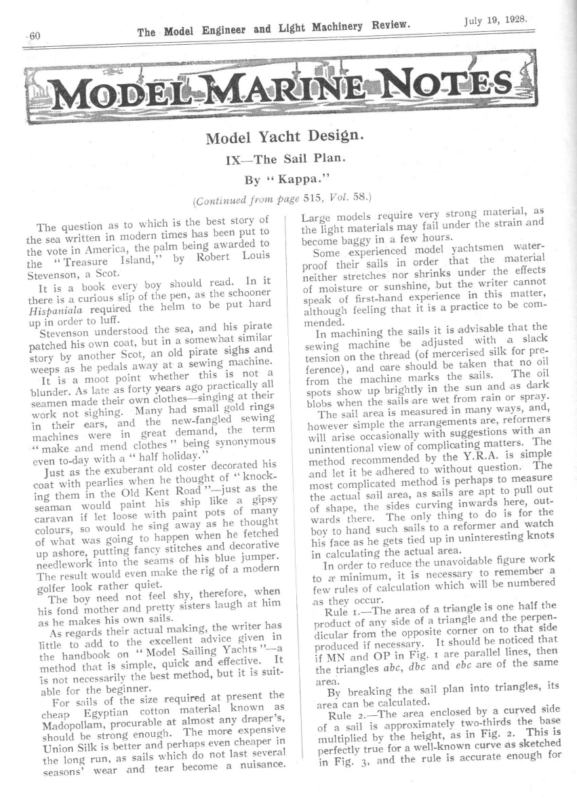
- The Geometry of Sail Measurement. The article breaks down the complex Y.R.A. (Yacht Racing Association) measurement rules into simplified geometric principles for the amateur builder.
- Triangulation: Since actual sail area is difficult to measure due to curving edges, Kappa recommends breaking the sail plan into triangles. The area is calculated as half the product of any side and its perpendicular height.
- Curved Edges: To account for “roach” (the curve of the sail), the area of the curved segment is roughly two-thirds of the product of the base and the height [Rule 2].
- The Fore Triangle: The Y.R.A. simplifies head sail measurement by rating them at 85% of the fore triangle (the area between the mast and the forestay). This is calculated by taking the triangle area and subtracting 10% and then another 5%.

60 ew. The Model Engineer and Light Machinery Revi July 19, 1928. Model Yacht Design. 1X—The Sail Plan. By ‘‘ Kappa.” (Continued from page 515, Vol. 58.) strong material, as Large models require very r the strain and unde fail may s rial the light mate s. hour few a become baggy in yachtsmen waterSome experienced model that the material Isla in order sails the ‘Treasaure their f proo r the effects unde nks Scot. shri nor ches Stevenson, stret er neith should read. In it the writer cannot but , hine suns or ture It is a book every ofboy mois of pen, as the schooner || speak of first-hand experience in this matter, there is a curious slip thethehelm be comto be put hard ired although feeling that it is a practice to Hispaniala requ d. mende up in order to luff. and his pirate is advisable that the Stevenson understoodbutthein sea, In machining the sails it sted with a slack a somewhat similar , adju be ine mach ng patched his own coat sewi and s sigh te silk for prepira ed old eris an , merc (of Scot ad her thre anot the by on y ion stor tens ine. mach ng that no oil n sewi a take at be y ld awa shou ls peda care he and as , s nce) weep fere not a is The oil this . sails her the whet s t mark poin ine t moo mach a the is It from in the sun and as dark y years ago practically all y of which is the best stor The question as to ern to put been has s time mod in ten writ the sea to ded awar g bein palm the ica, Amer in the vote nd,” by Robert Louis | plunder. As latetheiasr fort ng at their own Gothes—singi seamen made gold rings l smal had y Man ing. sigh not k wor sewing led fang newthe and , ears r thei in in great demand, the term machines were hes ” being synonymous ‘make and mend clot holiday.” half “ a with ay even to-d his rated t old coster deco Just as the exuberan kof ght thou he n whe lies coat with pearthe Old Kent Road ’’—just“ knoc the as ing them in like a gipsy paint his ship pots seaman would loos of many t pain with e caravan if let d he sing away as he thought colours, SO woul g to happen when he fetched of what was goin decorative ing fancy stitofcheshisand up ashore, putt jumper. blue ms sea the needlework into even make the rig of a modern The result woulder quiet. golfer look rath when The boy need not feel shy, therefore, him his fond mother and pretty sisters laugh at . as he makes his own sailsmaki ng, the writer has al As regards their actuexce n in llent advice give jittle to add toonthe‘‘ Mod el Sailing Yachts ’—aIt the handbook le, quick and effective. method that isilysimp the best method, but it is suitis not necessarbegi nner. able for the ent the size required at pres For sails of the cott wn as kno rial mate on tian Egyp p chea er’s, drap any st almo at le urab proc am, poll Mado nsive expe more The gh. enou ng stro be ld shou in perhaps even cheaperral Union Silk is better andwhic seve last not do h sails as run, long the tear become a nuisance. seasons’ wear and spots show up brightly wet from rain or spray. blobs when the sails areured and, in many ways,rmer meas is area sail The s refo are, ents ngem arra the le simp ver howe an with ons esti sugg with ly ional occas arise will licating matters. The unintentional view of comp le the Y.R.A. is simp by ded mmen method reco red to with The . tion ques out and let it be adhe is perhaps to measure most complicated methodsails are apt to pull out the actual sail area, as inwards here, outof shape, the sides curving to do is for the wards there. The onlytothing h boy to hand such sails a reformer and watc tied up in uninteresting knots his face as he gets actua l area. in calculating the unavoidable figure worka In order to reduce thenece ssary to remember to a minimum, it is n whic h will be numbered few rules of calculatio triangle is one half the Rule 1.—The area of a trian gle and the perpena of side any of uct prod er on to that side dicular from the oppositeIt corn ld be noticed that shou sary. neces if uced prod lel lines, then paral are 1 Fig. in OP and MN if of the same are ebc and dbc abc, gles trian the By breaking the sail plan into triangles, its area can be calculated. by a curved side Rule 2.—The area encloy sed hirds the base two-t atel oxim appr of a sail is 2. This is Fig. in as t, heigh the multiplied by sketched as e curv wn -kno well a for perfectly true for in Fig. 3, and the rule is accurate enough as they occur. area.
July 19, 1928. The Model Engineer the curves dealt with in actual practice, and Light Machinery which may differ from it slightly. The Y.R.A. measures and marks the spars at A, B and C for the mainsail and E, F and D for the fore triangle, as in Fig. 4. It then fixes the area of the head sails at 85 per cent. of the deduct ro per cent. of the fore triangle and then half of this (5 per cent.), a matter of subtracti on only. M yachtsmen have x T experienced a e Io X mast, N the 61 area of the mainsail is . 125 sq: ins; 2 | triangle—a normal proportion. To calculate this percentage it is only necessary to model the 25 “TOF fore Several with Review. : Pe et 6G, The area of the fore triangle is — 2 71-5 sq. ins. Deduct 10 per cent. or 7.15 or sq. ins. Also deduct half this or 3.57 sq. ins. Then 85 per cent. of the fore triangle becomes 60.7 sq. ins. and the rated sail area 185.7 sq. ins. It is always better to over-estimate the sail area rather than under-estimate it, so make it 186 sq. ins., and it is desired to redraw it at 800 sq. ins. From article V it will be remembered that lengths can only be compared with lengths, P&P b c Fig. 1.—Measurement of Area of Triangle. Se. Height ay —_— base —__—__——_—__> Fig. 2.—Measurement of Curved Edges of Sail. Fig. 4.—Sail Measurement. areas with areas, etc., and a length can. only be compared with the square root of an area, Fig. 3.—Measurement of Area having a Curved Side. difficulty in laying off a sail plan of a given area and a desired shape. A smart-looking sail plan is seen in a book, say, and it is desired to put it on a model. A simple method is to proceed as follows: ro) ia 7 a aa v —_— ai ——- 3 i ‘*¢ i 7 plan sailf~of the sail plan small* words “‘large’’ large sail area small sail area sail plan, the and ‘small’? should changed in the rule. be inter- From diagram C the ./8o0 is 28.2 and \/186 is 13.6, so that each dimension has to be multi- plied by a or 2.07, and this means eight or SIE in large Sat; ( CASEIN ryiil) SHE large 3. the corresponding dimensions If it is desired to scale down a In this case the rated sail area of the model is to be 800 sq. ins., and it is desired to lay off a plan to this area and of the proportions sketched in Fig. 1, article VIII. In that plan the height of the jib hoist from the deck is 22 ins. and the base of the fore triangle 63 ins. As the boom is fairly square os i and this is done by Rule The dimensions of the| Rd U1 SAM —! 2 ae Ss seach Fig. 5.—Method of Using a Slide Rule Lit iti) 4 2 3S 6789 go PS ETT
The Model Engineer and boy should nine sums and requires patience. Thecalc ulations 62 Light Machinery Review. and the use a slide-rule if possnoible more bother than open are then made with n he it of hang the gets whe ella ing an umbr place the slides as in Fig. 5 and thus: He should the glass n he should run diag keep them still. The the in ed dott wn (sho jockey or monkey each of the dimensions inram) the until it comes to g to be enlarged on the lower sail plan requirin nding numbers on the upper slide. The correspo What the boy has done slide are the answders. to number on one stick +s to have addeothear stic the k and the sum of another on the uct of the two if multiplied two is the prod ion, by subtracting together. Similarlybyformeadivis ns of the other. (We a bit off one stick 7 “3 dia ay Dont cramp ||’ the masthead | ey | | Dimensions 5 measured | fo Aeduckhd pr shrething of maktrial God la V\ Length of mast sh SE above deck between sacl & spare \ \ Selucage ste Aemmed 10 July 19, 1928. ectly. Fig. 7.—Effect of Battens Used Correctly and Incorr in The new sail plan becomes as sketched Fig. 6. er about the area both The Y.R.A. does not leec hes of the sails, but r of the bow in theofafte In an A-class limits the length arethenotbatttoens. be more than four model the battens in number nor more than 7.8 ins. long. The Xx boy should be limited, therefore, to 7.8 47” ort a supp will h whic ens batt for say, 53% ins. it capsizing, as in bow of about 2 ins. without Fig. 7- can be made to d suits The second and thir le to keep n. It is preferabthe the dimensions draw ler boom and keep thesmal to the one mast and owner as et, pock the in even or roll a in sails s with full his model many mile can then carry sails good fun ing miss out with of t equipmen Fig. 6.—The Sail Plan. owe our thanks to Napier and Oughtred for the once The dimensions of the new sail plan at slide rule.) become as follows :— ins., foot Mainsail: luff 51.8 ins., leech 55 ins. 20.7 foot 12.4 ins. Jib: luff 24.9 ins., leech 31.1 ins., Height of jib hoist from deck 45.6 ins. Base of fore triangle 13.5 ins. 4.15 ins. Height of gooseneck from deck area to be Checking shows the new sail ‘ 6 nsa8 20. + 85 x eiG 1.8 X X 207 SES = 535 + 262= 797 Sq. ins., which is quite accurate enough for the present purposes. 31:5 Fig. 7.—Correct Method of Staying the Mast.
The Model Engineer and Light Machinery Review. 64 neck often fails when the strain comes on the kicking strap, and it is a matter of importance that the lower security of the latter should be made fast to the mast and not to the deck. Moreover, it should be in line with the axis of the gooseneck so that the boom can swing freely as though the whole sail were hinged. 3 IE Aa in article VIII. Then piece pins through the luff of the mainsail } in. or 3 in. or so from the mast and gently pull the sail-cloth towards the mast. The effect on the flatness can be seen at once, and by going up the sail in 3-in. stages or so it can be seen by the pin-holes exactly how much requires to be cut out of the luff in the event of there being a bag in the sail in order to cure it. If it is only a small amount this can be reefed up neatly by needle and thread. If it is considerable, pencil a batten line through the pin holes and cut the tape off with a razor, Copper or wily Corman i July 19, 1928. ae = Sher hard brazed or Sher seldered af Fig. 11.—The Gooseneck. When bending the new sails to the spars do not pull too hard at the corners—just a gentle pull at first until they are well stretched and then keep a sharp look out for bags in the luffs by placing the model on a table resting on her keel and bilge with the sails set as in Fig. 2 (A) retape it and fit new eyelets. In this respect the jib is more important than the mainsail, in the opinion of the author, at any rate. Don’t be afraid of a little metal work for the flag and don’t overdo it. A flag had better be too small than too large, and a racing flag 14 ins. square is recommended. It looks smart, and the novice will take more interest in the Silk ribbon boat and therefore sail it better. painted with gold paint used with amyl-acetate and a camel-hair brush is handy for racing flags, but the stuff with the smell of pear drops is highly inflammable and should not be breathed too freely as it dopes one with a bad headache. Perhaps now it would be better if the sails were given a rest and the design of the hull proceeded with. Before the boy can design a hull he must be able to draw one, so let that be dealt with next for a change. (To be continued.) Model Yachting Association Notes and News. By the Editor of ‘‘ The Model Yachtsman.”’ The Gosport Regatta. The British Championship (and Selection Races) at Gosport on July 30 and 31 and August 1 and 2 have attracted twenty-eight entries. Amongst these are many old and tried boats, such as Defiance, Gertrude, Vigilant, Little ne, Nell, Gleam, Gareth II, Pat and Hermio which has been completely rebuilt and vastly improved. As Mr. Tom Willey’s boat has always been pretty ‘‘ hot stuff,’ she should now be very much in the picture. In addition to the old stagers, there are several interesting new craft. Amongst these is Modesty, a new boat for which Mr. W. J. Daniels has just built the Mr. R. Fairey and will sail on behalf of Miss South owner. Another interesting boat is McLave rty, Africa, entered and built by Mr. have Hon. Secretary of the Durban M.Y.C. Wemodel inspected this boat, and she is a very nicebut we from designs by Mr. J. G: Feltwell, arrowhate the hefty gold and black stripe with on her heads at each end which she carrien s Turner ’s white topsides. Twinkle, Captai dangerous ; latest design, is also likely to be Madeleine, Mr. Crawley, is another Daniels model and a fast boat; and we must also mention Iolanda II, Mr. W. Shell’s new craft, Mr. which has been . going extremely well. Shell is a very clever skipper, and we expect to see his model finish in a very high place. Altogether it should prove a very interesting race, and although we have only mentioned about a third of the craft entered, there are many good boats among the others. The International Races are to be sailed on August 4, 5 and 6. We understand that the American Selection Race will be quite as big an affair as our own Championship, and it is certain that the U.S.A. representative will be a speedy craft. Mr. John Black’s boat last year was at her best in light winds, and much will depend on what weather we get. The German Selection Races have attracted a number of entries, and some of the new boats are by very famous designers, such as Rasmussen, Tiller, etc., and we can, therefore, expect something sretty good from this country also. The French Selection Races are being held in Paris, and, with the experience of several years behind them, we may hope for hotter competition from
153… ew. Revi ery hin Mac t Ligh and neer Engi el Mod The August 16, 1928. d for truth at each cke che be t mus al, zont hori or s Thi . sors scis and m. the e, g knif win , dra pins r spline,can be added to very considerndablyby endVertafteical lines should be drawn by a .teeset–squsquaarere e, ent scalipm equ ,n butdesigntheingautahormodelhasawafouy from inapplpref erenthece upptoertheor lowuseer edgof esthe,of the board,er hrienadvce,antage wit to whe ied expe items and it must be emphass and unlessstattheionswatare the that d that ise es, ianc appl no h wit e hom ical vert nt. icie s,wn buttrultocy, kthelinecurved surface of rac enuThemeratesmadllearest drasuffwing-board recommende edbeingis line hullin thecansethe dra y ccu fac ina sur any le who and ut 24wooins.d—nbyot16bouins.nd, theon its workin abo surwinfacg-e notlinesbewillfaircaued seat all,the begH”innergramucde hpencworilry.and as g ofby soft dra the ch whi od intoOne edge of the board hisHeskillshouincr ld useeaseans So“ will the hardness of his pieccanesnotof beharpresdwosed. pins ds boar best the enpaduseofpencglasilss-pawithper and tsm ugh ight, a strip of hardwood | penc dra stra led y skil ectl as perf be ils, ld shou or file a m, with the id on inla H’s edge y man one e | havproecting slightly outp guid shoues—ld boy lin edgereofmorthee being used to sharpendrathewinm.g very The fine or squa of thees side teethe r ove e stri tim s te Thi was . pine not soft wn boldly so that they are dra be willg theas boaallrdtheitselhorf. izontal lines are the uld sho y trulYety thaasn lon ble. visi y inl pla ays angne-ed alwTwo grades of drawinthigckpapsheeretareof reccheomcan. thebesearrrefi andightthis , llel para ly ap,the tru wn dra y e, tel -edg era mod stra —a ry ina ded ord men an h wit ry. ssa to ece ned unn pin is ome ch bec d whi er oar pap g-b g win win dra the square is a very useful instrumeto ntbe smo othasdraa foundation, ovetrir whidgechpapiserlaid(noa tshetheet tsthein teemen rd Yet boa er bett is it not, If ifwitithouist trulit. y Allguidedpara.llel lines, whether vertical of thin transparent car RATING PARTICULARS. ins. ed Length .6—..8.1) ..– 40.1 sur Mea LiL, ,, 3.75 (10 1.5 , Tax Bow bt os . LIS -) 5.6 .8— (10 $ , Tax rn Ste st Oy «AT 1. 2) —7. (26 ¢ , Tax th Gir gt s O68 . as .Tax “9d.” d 88, 34. .. 216 4/1 Sail Are,a $(4 VS Mre .3) 3.76 » eboard .54+3.5+3 > d+ 4/S—F not to exceed 82 L,L,+bt+st+gt+ ins. Bese g-IN. TE Lead keel, as drawn 14.0 Ibs. 5 les. Beam (.w.1.) 10.7 ins. Draught 8.3 ins. Displacement 20.2 Ibs. eet SIX-METRE MODEL. :
The Model Engineer and Light Machinery Review. 154 ordinary tracing paper with a shiny surface at this stage). The transparent cartridge paper can be purchased in rolls or long lengths most economically, and errors in pencil can be erased from it without difficulty. For measuring purposes compass dividers are sometimes used, but for the present work measuring strips of surplus thin cartridge paper torn into spills over the edge of the rule (as in Fig. 2) are more suitable for this type of drawing, being more expeditious and less likely inexperienced to make holes in the paper as theThe use of the use of compasses is apt to do. measuring strip is illustrated in Fig. 7. The set-square is preferably of 45° angle with s of thin or bevelled edges in wood and the square es. thin transparent celluloid have handy qualiti The ruling edge of the tee-square might with advantage have a thin bevel on it also.a large If later on it is desired to design such by 42 ins. model as an A-class model, a board 29 ins. with tee-square to suit is a convenient size for half-scale drawings. ce are of The curved lines met with in practi purpose the for called be them —let two kinds short ’’—the of model design ‘‘long’”? and “ ture and the curva former having a long radius of matic al language latter a short one. In mathe so it is customary to speak of the short curves the defined as having a greater curvature than hten out long ones—the long ones as they straig curvature at all to a straight line having nomenti oned so that eventually. This is only curves in there may be no confusion, as many and short s place some in long are n model desig in others, as in Fig. 3. August 16, 1928, make a pile of shot on the parade ground—first here, then there—always shifting the shot, so it is better to make the weights rather light to avoid fatigue, using them for long curves only. Perhaps if he uses pins the number of holes in the paper will remind him that he is only at the beginning of things and that it would be better to redraw the boat. when finished, as there is a temptation to build the boat the moment the drawing is finished. It may not be worth building at all howeyer fair and pretty the lines may look on paper. If a drawing takes some time there is also a danger that the designer is too easily satis- fied with it, and he is advised to put it away for a day or two, and then, on looking at it again, he may wonder how it was he could have perpetrated such an ugly design. The question of what is pretty and what is ugly should not influence the designer overmuch, however, and he should proceed on the understanding that if his work is well done and that he complies with natural requirements the model will automatically be nice! Ruskin has laid it down that if the work is done as well as it can be done it$becomes a thing of beauty. Tastes and fashions change considerably and the writer can recall how the schooner bows of racing cutters such as Thistle and Iverna were looked upon as the last word in beauty, the artificial cock up of the sheer line aft on the long counter constituting the acme of good taste and prettiness. They made the older straight-stemmed yachts such as Genesta and Ivex look ugly and commonplace, and yet the latter were admired very much in their day. Then came the Roman nosed bows of Britannia, Satanita, etc., and at Yet as Britannia outclassed the old Thistle, then renamed Metea, the new bow became quite long Curves such as diagonals are mainly vary curves if drawn correctly, buttock lines be considerably. The batten or spline shouldones first a shudder of horror went through many. for the short curves by the beginner, asoftheir unuse will force him into the employment he desirable shapes. At a later stage, when find that wishes to ink his drawings in, he will are indisdrawing instruments and such curves r of mechanical pensable. Yet this is a matte drawing rather than model design, the subject sheer line of the simplest possible character. No boot-top in bronze or copper was provided, no used for the long curves and the shortcurves drawn by freehand. | Various French be used and pear curves should on no account under consideration. The batten or spline can be used with ordinary household pins to keep it in place, as in Fig. 4, ionable holes but the pins necessarily make objectthe sailing of affect not do These paper. in the takes a ner desig the time in if but , the model lead find will he , nship htsma draug his pride in t. The writer weights very useful in this respec has two sets of five weights, the light ones as Fig. 5 being of handy size; the. sketched in heavier weights other set was discarded as the a form of shot to work ng drawi the d reduce n balls soldrill. In the days of round canno lled to compe be would hment punis under diers Then came an American Vigilant popular. with no pretence at good looks—nothing but a plain well-turned-out curved surface with a gold stripe or fancy mouldings—another horror, that in its turn commanded the greatest respect purely on account of its being a job done as well Possibly none of them as it could be done. would be regarded as_ particularly beautiful to-day as regards the hulls, Whether the crazy light masts of to-day are more beautiful than the well-proportioned and splendidly-stayed spars of 30 or 40 years ago altogether. is another matter It turns on which job is carried out most faithfully. As regards the frequency of dismasting and breakdowns, the difference is perhaps not so very marked. A more striking example ofa complete change in popular taste or custom is found in the sheer line. In the old days of sailing ships, say, in the middle ages, when ships sailed almost entirely with the wind behind them, the height of the sheer, or freeboard, was greatest at the:
ew. The Model Engineer and Light Machinery Revi August 16, 1928. UA-4 t r ies ty e or gul re ofMoPr en lt Ga of diagonals req st 2 $ y A handfine. preferred. Avoid 3 pi r Curves, Lance wood ftve pins or ive ights P n. Fig. 4.—A Pine or Lancewood Batte ge, and the came a graduale chan stern. Then dja times had nt rece mor of r mme win -sea deep e craft cam n The s. bow the at d boar free e mor h a most wit ters drif and lers traw am ste as h suc board r at the bowstheandstenorn—free exaggeratedth shee fore the at of king spea wor at all g much bein ters drif and lers traw ing sail aft and of usefulness r own spheresific the same. Infinetheicraf ent jobs ofe magn all t, all are they to mak in models,crafif t itinisrouwisghhed work, and weat water, it is y them fine onherl being too better to err the freeboard forward, small yachts and the closely in n too little,copi great rathershotha ed too be not uld ay to-d of re respect. There are several instances whe this are severe fullness of the bow the taxes on the the r cases othe In lost. is bow of r shee the and age freeboard is encouraged the where the aver is artificially increased and an ugly freeboard aftresu lt. boat is the be natural and So in the model work try and | _ thin carlrid(ge paper 3/”_pe ae fices—do the job well and the avoid such arti result will be good. gner is now invited as a first The young desi ly copy and fair up the lines of example to simp six-metre model depicted in | a1} in. toThethewritfoot that it is anyer does not claimresp Fig. 1. ect. It is any in way the of out g thin elf. hims do can he best the ly simp ows: ed is as foll hod recommtheendstat Now the metspac | ed ber num ions of ing the e ang | Arr er is con- the drawinge papthe squares | 1, 2, to y 14,filleSOd that arrang then and entl | veni vertical sects ions of g win dra the on wn | sho 6, so that the sides the e square are thes of in Fig. sections. n wee bet g cin spa the ter | one-quar w the sections by copying the by eye m the | Then drafreehand on the squares, taking special and by re the sections cut the point of crossing | note wheline rks, as | of two s using these spots as landma | ld The sections are all short curves, and shou it were. yo Short Corre K shorf Long shoyyre es. Fig. 3—Differences in Curv Gounlersurnk Screws e” Waaden Sole Ye thie ati: ae w& Tilo. 5 Most Lead weights with 3, Arawn curves can quired re e ar SOx occasionally Strips. Fig. 2.—Tear Up Scrap Paper into Measuring Fig. 5.—A Handy Size Weight, 4-44 Ibs., in Lead or Whitemetal.
The Model Engineer and Light Machinery Review. 156 August 16, 1928. ‘ and counter, particularly if they are very full, the buttocks are preferable to diagonals for fairing, the spots where the buttocks cross the water line being invaluable for shaping the ends of the water lines in the plan. For shaping the topsides between the shoulders and the quarters, there is little to choose between the water lines and the diagonals, the latter being the safer. Buttock lines become of little use towards the sides of the model and sometimes they are not even drawn at all. The nearer they are drawn to the centre line the more useful they become, especially for fairing up the turn of the fin into the bilge at the garboard. In a hull form of the type shown the water lines may as well be left entirely alone until the profile drawing and sections are in agreement. Then they can be projected directly by strip as shown in Fig. 7. “These curves will be found difficult to draw completely by means of battens, the midship portions being more or less long curves and the ends in many instances being decidedly short. For a hull form of this type, the youngster should on no account design on the water lines first—there is no rhyme or reason about such a method. The fairing by means of the bilge curve exerts Body Plan of 1%-in. Six-metre Design. a most powerful influence on the general character of the curved surface, showing up inaccuracies which would be extremely difficult to be drawn by eye. The water lines are long in places and short in others and should be left out of consideration entirely until the sections and profile drawings are fair, the water joining up the points as shown. The the profile drawing and the plan, using strips as shown in Fig. 7 for plotting the resultant curve should be drawn in both © positions of the vertical and horizontal touch the sloping spots where the sections lines. The positions of the diagonals should be chosen so that they remain long || f | J| 4 curves throughout by not crossing the , If they are allowed to do so they become short and it may be impossible to draw them with an ordinary batten. Furthermore, points such as P, Q, R, and S should be selected so that the diagonals cut the sections as near as practicable at right angles. A diagonal such as MN will leave little to grumble at at stations 3 to 11, but at stations 12 and 13 it not only cuts them obliquely but becomes a short curve as well. If such a diagonal were forced by the batten, the whole character of the surface as a wellturned-out job would be lost. For certain spots such as under the bows ¢ J a | ee 2 5.2 “NX – M Load Watt Linc V7 V7 | si aN, SS va \ KOA — ; =F Ar A Waterlint =] T (1 rn 6 | | \ Jo” \ aS /} | WAZ { |eae Y |i —— \ls S | Rr Srales of Sqvarss on one guarker of Spac< Behe we bh ° he Seelions | _! Fig. 6.—Sections Drawn by FreehandTover Ruled Squares Preparatory to Fairing. P } } \2 me .— Tat Wa hy Osa | S—— — 1 \o? i4 Wa" E | > a { ~ I ia | __| yntans of Wafer lines 7 Yee | | x Below J fair by, Q bilge curve. 2 TA d4 onal cess, draw in the diagonals and the bilge € curve. The latter is effected by touching , each section with the 45° set-square and ! 3 165. + should not be altered in the copying pro- o ¥ 2 wis ¥ lines in the fin being exceptions to this rule. Having drawn in the sections and noted the landmarks shown as dots, which
\ August 16, 1928. Review. The Model Engineer and Light Machinery 157« a The paschons of fornks P achermine fhe Shape of the Profle GRA pole Ul Ursa. ‘Diagonal . Fig. 7.—The Use of the Measuring Strips of Paper and diagonals ned. y of sectionse, high delete by theunlestud trai ly wer eye the ss s water line as a servant— must be treated bec The bilge curvefair omes a very It . only ing of ns mea as a by the out ed fair aces surf and er, mast bad to be apt are e curv e bilg the of use l principa and flat on the sides and hard in the bilges ions water row and deep sect In models of nar drawings the and ant ort imp e mor ome bec s line be exceps time at can type this of els mod of bottoms. tionally sweet. and For the present, before studying the whys, the the wherefore of the many different type of copying in. left with the task novice will bempl he is able as well as en giv e exa the pencil S. DESIGNED WEIGHT Ibs. 2 Hull, bare minusfenefinrs . Deck, with stif ws as ae ns i .- ee .. 20 a .. Wood in fins sail ing rigg and s s, spar t, Mas al fittings Bolts, nuts andandmetqua drant e Rudder, tubish and sundriesask Paint, varn dra Lead keel as wn .. Total weight ro ai ie es sh .. 214 ozs. 12 13 5 14 8 3 12 0 3 Regatta. The Model Yachting Associationpor t. The International Races at Gos er was Ito. The winnort, finished first with ass and A-cl ish Gosp of Brit e, the Lanc of nd Reg. rou Mr. ry by ina gned lim pre desi The hip was sailed on July 30, 31 and Jones. A. Mr. by d saile and ed own ons mpi Cha 1. There were twenty-eight entries but rnational Races wery.e Entrants for the Inte August ts man boa o -tw nty Sweden and Gerfelt twe t A., tha atched sor. Britain, France, U.S. six of these edscrthe e they that aus bec d tche scra rte sta den Swe e thes fac Of ly , and actual internationatol form e $.W. breeze atto was not upcomtopet there was a ornictwo boat r thei bogt r The first day afte thei ked ng bac owi it e , Germany could not the start, but r a heat a reach. After sure steamer the week- n by a plea being cutredow the races. becamea second-suit breeze. ard and the Souitthw l w pretty wel lunch ble y wit.h 27 points each made and Modofest Fantasiat sco res the day m practically aaspacal there wass the The next day nkwas re ard erw aft but ch, lun before d up and down the pond. the bes breeze dea ing Easscoterrerlys for 25 and Top ne 23- the day were Little Nell Hermio was sailed suiinteda nd of theditday The lastwinrou irablymade a s ion con and d, . fine S.Wde (last year’s winner), adm and Gertru of 35 points for the day.sheFolly II possibe le27mad inary the prelimwhi first twetolvecomboapettse inin the ch Only thee elig l, fina ible wer round led on August 2 sai Nell was On aggregate over the two rounds Little ional Races rnat day of the Inte On the firstboat Weaver, gained Patsy, Mr. J. seco the American On the doindng daybadlthe a lead of 4 ,poinwhits.ch had y, n French boat h improved formbee ish Brit the and , showed muc and passed Patsy, and the day ok boat overto h the scores: Great Britain 71, finished witFra nce 35U.S.A. 62, a ional provided of the Internat The final day By t boa ish Brit the me h-ti lunc dour struggled.her lead to 14 points. After lunch had increasean regained almost all he had lost, the Americ l board of the afternoon provided the and the finarace. Final scores: Britain 107, decisive end befo | U.S.A. 105, France 49.
The 300 Model Engineer and Those engines were going full speed waters. astern in a few seconds, which saved a disaster. Afterwards I was complimented by the captain, who told me that the strong current had nearly landed us on a sand bank. We have currents on our lake at Tynemouth, and probably many enthusiasts are compelled to use streams or other waters with perhaps a considerable current. It is well to remember when estimating the speed of models that this is actually done through the water and not by land marks with a swift and favourable current. A True Current Fish (?) Story. I remember some time ago running one of my models in a steering competition at Tynemouth, and the score was far below my expectations. Everything as far as 1 could see was in perfect order, which made me inclined to blame currents for the bad steering of my model. Imagine my surprise when I removed her from the lake to discover about a dozen shell snails sticking to one side of the hull. These inhabitants of our lake had no doubt accounted for the numerous sea birds which I had observed at the time. One of our members said, “Another column for THE MopeL ENGINEER.” “Tt is a fish story, Tom, and they wan’t believe it’? commented my colleague Mr. Haworth. However, there it is, and I give nothing but the truth. Preventing Damage. Light Machinery Review. September 27, 1928. tions of the engines when the telegraph has rung stop may easily result in a broken blade. In the case of a partly broken blade, at a time when a new propeller cannot be fitted, it is advisable to cut an equal portion off the opposite blade to balance as far as possible the centrifugal force and save damage to the stern tube and gland. Before turning the engines in port for over- it is essential to always hauling purposes examine the propeller and see that all is clear. Serious accidents have occurred through this oversight. A small engine called the turning engine moves the main engines into the required position. A Notable Propeller Repair. There are numerous instances of remarkable – repairs to propellers at sea which show the skill and resourcefulness of our marine engineers. I remember about 25 years ago seeing and examining a propeller at an exhibition held by Palmers’ Ship Building Co., at Jarrow-on- Tyne. This propeller, about 8 ft. in diameter, was actually constructed by the engineers of a steamer and was built of plates, angle bars, wood, etc. This notable repair was freely commented upon in the Press at the time, and it appears that the steamer lost her propeller in a lonely part of the ocean and was drifting towards some cannibal islands, so something Part of the tail end shaft had to be done. remained, to which this improvised propeller was The propeller, of course, is very liable to secured and the steamer safely brought to her damage, and great care is necessary especially destination. I believe it is still preserved and when working big steamers into the docks. It can be seen at the Mercantile Dry Dock, is essential that the manceuvring of the engines Jarrow-on-Tyne, where the vessel dry docked. should be done promptly. A few extra revolu(To be continued.) Model Yacht Design. XI—The Hull Calculations. By ‘‘ Kappa.”’ (Continued from page 157.) It is a moral truth that an evil deed brings its consequences. They arrive in many different ways, but how or when cannot always be foreseen. Shakespeare, in illustrating this in ‘‘Macbeth,”’ took that inquisitive villain to see the witches, and he enumerated in detail the loathsome ingredients they stewed in their pot. These were exactly two dozen in number and a mathematical crank might argue that this is a case for the duodecimal system, as the forest went subsequently for a stroll as the witches foretold. In model yacht design the success of a model is often attributed to some magical propertvy— some peculiar place for the C.L.R., some special prismatic coefficient, some ratio of length to beam, a displacement curve with certain mathematical properties, quite commonly to the possession of some dark knowledge on the part of the designer, but it is advisable to put all black magic into the cauldron, sticking rigidly to simple truths and giving the magic a wide berth. The shaping of the hull requires that the boy should be able to satisfy himself that the boat will float and balance correctly and he must in the first place make himself familiar with the methods of finding the areas of figures bounded by curved sides. Happily, these can be reduced to curves of about six different characters as in Fig. 1, and in each case the area is the length multiplied by the average width. There are several methods employed, the simple one given, which is approximate only yet sufficiently accurate for use in the design of the largest models; Simpson’s
The Model Engineer and Light Machinery Review. September 27, 1928. 301 the boat. The actual displacement curve is similar to that shown in Fig. 2, from which it will be seen that the ordinates b, c, d, etc., represent square inches and the distance between rule which is more accurate but which may be disregarded for this work; a Russian rule which is more accurate still, yet quite unsuitable for the present purpose ; and the use of a planimeter, an instrument which costs several guineas. the lines inches, the result being represented cubic inches. Rule 5. It will avoid confusion and facilitate all Rule 4. The simplest method is to divide up the areas as sketched and add all the lengths together a, b, c, d, and so on, deducting half the lengths culcations of areas, volumes, etc., if the indivi dimensions on the drawi are read off by means of scale, not as so many in actually on the paper, but as the actual dimensions represented in the full-size mode] The positions of the centres of gravity of the displacemen curves should not be ca lated. It is just as accu and every bit as scientific + trace the curves on thin trans- Heeled Total’ Section (00 Sg. ths Jin parent paper and cut them &8 spills Corve PQ= aepth (4) Immersed Half Section ( so Area = Som of \ Lid on a eee | ma (Babece-oo4 se €) moltiplied by S ara 7 walerplane a OP from She a ad 6 er (é) Heche wael* oT £ ) a tions of the centre of the displacement, or centre of buoyancy (C.B.), as it is called should be determined in this way. It is necessary to determine the positions of this important heeled, in order to insure thar the boat does not trim by the head or by the stern when completed. If the model is of good shape a slight trim by Jobat A (Y) Lon gi todina/ Dishlacemenk Corve Fig. 1.—Six Typical Curves. that the paper does centre both when upright and | frequen tly nothing. so not buckle—and balance the curves on the blade of a penknife, as in Fig. 3, and the longitudinal and vertical pos’- vertical Displacement @ our with scissors—press them int BM = BEES irs Selig the bows or stern will not affect the performance of the model when sailing to any marked extent, but it is desirable that the calculation be made as accurately as possible. By the method given, if it be made twice, it is practically impossible to make a mistake in the arithmetic without it being noticed at once. at the ends such as a and I, and multiplying the nett sum by the distance between the lines. In such an instance as Fig. 1 (B) the area is that of the triangle plus that of the curved portion and Rules,1 and 2 may be used. The beginner should therefore calculate the areas of the immersed half sections of his drawing of Fig. 1, Article XI, and plot the totals to any convenient scale as in Fig. 1 (C). Then if he calculates the area of this new curve the result will give one half of the displacement of e The displacement with the model upright can be read off in pounds from Diagram A_ in Article V, but it is as well to recollect whether the displacement is of the whole boat or only one half of it. The displacement in cubic inches with the model heeled must be determined, and it is convenient to take the new ‘‘ smooth water ”’ water-line through the centre line of the model as in Fig. 1 (E). The areas of the immersed wedges should be added to the areas of the immersed sections, these respective sections
302 The keng thening forkrd over A ang Model oP U i o F and Light Machinery due wet , Engineer Curve body -_ er of PQ = feel, Review. September 27, 1928. kenglhen ing Uae ho fee i ov kang Tolet Meeled Section Aol c4# Oslurbance PR Saale Caused oy fla R area on ff : devble thet the QR yr Ke Png hay tellin, at Fig. 2.—Longitudinal Displacement Curves. having already been calculated and plotted on : : ‘ the upright displacement curve, and similarly the emersed wedges must be deducted. The heeled displacement curve can then be plotted as in Fig. 2. | | The heeled displacement curve has a larger area than the upright one, and if they are to be the same then the-water-line MN must be calculated by a trial and error method as in Fig. 1 (E), but this is quite unnecessary. | | If under one suit of sails, the large one, : the | | | | | | . labour in the calculations to simply steer the middle course and make allowances for neither the lifting nor depression of the hull. The exact determination of the heeled displacement is unnecessary except inasmuch it is length ae to beginners ed what a th‘‘ momenti of sci inertia”’ ta Heit as 2 term? used in the matiral ‘sciences: to measure the disinclination of a body to commence rotating, or to alter its speed of rotation about « given axis, under the influence of a given twisting moment—and for the present the begin: ner will the moment be asked of to accept : : inertia : Fig. 4, denoted by I of the a 1b? is eo I statement rectangle, that as : in (inches raised to the fourth power). necessary to ensure that the centre of buoyancy | of the heeled displacement curve does not move either aft or forward from its upright longitudinal position. If it moves aft the stern is lifted and The volume of the displacement is V cubic inches which the boy knows how to determine. Rule 6. Bouguer showed that the height of the transverse metacentre above the centre of buoyancy the bow falls and vice-versa, and it is desirable that it should not move at all in a fore and aft position. It must move over to leeward as she heels. This is unavoidable and the amount it moves becomes important later on. = . is given by the expression BM I = vy? where I is the moment of inertia of the load water-line The calculations so far given are sufficient to plane. ensure that the model floats correctly, but in the balancing of the hull sections it is necessary to determine the position of the upright transverse | The moment of inertia of the load water-line plane metacentre. The longitudinal metacentre is somewhere up by the mast-head and its position is of no interest to the beginner as far as the writer is aware. Displacem at shape his model and make her shipshape. He may be able to make her shipshape by eye or he may not. ee model lifts out of the water slightly as she puts more of the lee side into the water than the weather side takes out. Under small canvas she may be actually depressed into the water and . : : observation confirms this so that it saves much : he is anything but a beginner, but its position is of the first importance in assisting him to These articles are not the place to describe at MN be the true water-line under one suit of sails, it cannot possibly be true for the others, -as The position of the transverse metacentre (M) is again of no interest to the beginner from the point of view of the stability calculations—he need not bother his head about such things until 1b3 approaches | | | | Curve the value of ——, 12 the more nearly the latter approaches a rectangle in shape and for a water-line of the fairly full round end type depicted in the design in Article X, it may aed Grd Wd wha SN —__——<—_* \ ee G Fig. 3.—Determination of Fore and Aft Position of Centre of Buoyancy.
where | is the length of the be taken as load water-line and b the maximum beam on the water-line. The actual determination of the moment of inertia of any shaped water-line is given by the following rule. Rule 7. The moment of inertia of the load water-line plane is the sum of the cubes of half the waterline ordinates multiplied by two-thirds the distance between the ordinates. The half ordinates can be read off by the scale and jotted down one under the other and against each one in another column the cube of that number can be jotted down after being read from Diagram B, Article V, where the cubes of all numbers up to to ins. can be scaled with accuracy. It is as well to note in Fig. 4 that the half ordinates a, b, c, d, etc., are those from the centre line to the water-line, whereas b in the is the total beam on the water- expression \ en ! cil drawn with precision from the lines of a small model, the sides of the squares being calculated, the sections and profiles sketched in by freehand leaving nothing but the fairing of the large drawing to be done. rule is mentioned as it is dangerous to This e a model proceed on the following lines. Supposheavy. It is right for length but 10 per cent. too ines might be thought that squeezing the water-l together by 10 per cent. is all that is necessary (or, alternatively, squeezing the buttocks 10 per and cent. more closely). Such a method is risky in the first false. If the model is balancedb the balance. place, such a distortion will distur of the Neither distortion will affect the trim model, but either may spoil a good boat. They a es foe SS as 6 ~-GREA folation s i CB cb == (2 Ts oo | = The use of this rule enables minor adjustments to be carried out and it also enables bea large model such as an A-class model to Momenl- q (neva = { eee 303 The Model Engineer and Light Machinery Review. September 27, 1928. Jha 1p Crease ho [raed Fig. 3a.—Determination of Vertical Position ofCentre Moment of Inertia of Water Plane app roximatety _CbF_ /9 @ 22 Fig. 4.—Load Water Planes. of Buoyancy. line. The foregoing rules are all that are needed for the design work pure and simple, and the beginner need not bother his head about any more save the following. Gn the completion of a design it sometimes happens that the model is too heavy or too light for the intended length and the following rule for conversion may be useful if the sections are drawn on squares as in Article X, a method that is recommended for general use. Rule 8. The weight of a large model Distance between the ‘stations in large model ‘the The weight of a small ~ Distance between small model stations in model Sides of squares on large sections squared 08 ise Sides of squares on small sections squared = squares may improve a defective one, of course, but con- siderations of the metacentre tell one what he can do and what he can’t. It will be noticed that in each case the water level is drawn as dead smooth and yet it is plainly disturbed in actual practice. The beginand ner should master the calculations given the author believes that there are no more than are really necessary, so that this ratherof dry the subject can be left and considerations shapes proceeded with. and If the figures are kept in their place their regarded as simply a means to an end, are assistance is invaluable and the resultscu.given ins. of simple truths in the sense that 27.7 hand, other fresh water weigh 1 lb. If, on thefirst essential the it is claimed, for example, that of of a design is that the centre buoyancy of a
The Model Engineer and Light Machinery Review. 304 model should be some special percentage of the load water-line from the forward end of the water-line, then it is safer not to use figures at all and to put such statements into the pot as being black magic. Clark Russell, in one of his short stories, tells us how the shipbuilder of the times of James II calculated the displacement of his ship. He made a block of wood sufficiently large to envelope the underbody of a model of the ship and weighed it. Then he weighed the carved underbody and as he knew that 35 cu. ft. of salt water went to the ton, he knew pretty well | September 27, 1928- therefore the displacement of the ship if her overall dimensions were, say, go ft. long, 20 ft. broad and ro ft. deep when finished. Such a method is correct and just as scientific as any other as, if the wood is of good quality, the result is true. It must not be supposed that because the language used to-day smacks of mathematics it is scientific—it certainly is if it is true, but not if it is false. The dry as dust portion of the work is about finished now, so that the design can be proceeded with without being entangled by so many figures. QUERIES «x9 REPLIES Querists must comply with the Conditions and Rules given with the query Coupon in the Advertisement Page of each issue. Selections from Queries recently replied to. 2388. Rewinding Small High-voltage Generator for House Lighting. F. W. (Kensal Green). which was a small electric machine It has a primary Q.—I have wound for a telegraph company. and secondary winding on armature, to take D:C: 2887. Aero Dynamo for Charging.——W. A. W. (Upper Walmer). a wiring diagram of a 12-volt Q.—Please supply 250-watt Lucas dynamo. I want to use it for accu- supply on primary side and give D.C. on secondary. I wish to use it as a dynamo to light about six lamps Will you please explain the for house lighting. working of this machine. My idea is to run it from a small engine. Would I have to have it rewound, and what would be the best voltage? This is what it is now: volt 100, primary 0.5 ampere, secondary volts 100/120, amperes 0.5; revolutions 2,000. A.—The machine appears to be a motor generator arranged to give 100 to 120 volts, the supply being only roo volts, but we cannot definitely indicate the particular purpose. Perhaps it was for charging a Diagram of battery of about 48 small accumulator cells similar to Connections for advise you as to its adapta- Lucas Dynamo. those used for the high-tension battery in wireless working. We cannot unless you send us a bility for use as a dynamomachine with particulars dimensioned sketch of the and of its construction and, if possible, the gauge primary weight of wire on the field magnet. If the side is shunt wound for 100 volts, it should give about roo volts } ampere, and the secondary about Charging from S se wo . 120 volts } ampere, the armature being driven at increased speed, possibly 2,500 revs. per minute. But the machine may not excite itself and need to be entirely rewound for a lower voltage. The output aa ' | battery wind- could probably be taken from a single armature the commutator. This would simplify ing and one winding. About 25 volts would possibly armature be suitable but we cannot judge without knowing the dimensions of the commutator and brushes. Wound for, say, 25 volts, it might give about 4 amperes at, “say, 2,500 Or SO revs. per minute, about 200 candlepower, half-watt lamps. mulator charging and am uncertain as to the threeA.—These dynamos are “ air-rated,’’ that is, intended for use in high altitudes and under entirely different cooling conditions than those which would point terminal block.
aT.< rat mile P MODEE-MARINE= S SEE g o AAA OHA = S S QS SSS Model Yacht Design. XII—The Guiding Principles (Part I.) By ‘‘ Kappa.” (Continued from page 304.) In order to speak the truth it is necessary tod preten know what it is. The writer does not written on to have read everything that has been d much the shapes of boats, but, having studie to a condition of of it, he has been reduced been known to laugh bewilderment. Horses have tame them, and at men and their efforts to too would do the perhaps yachts and models same if they could. Men like them all the better for it. that It has been laid down among othern things is to place desig the first essential feature of the cent. of the the centre of buoyancy at 55 perforwa rd. This water line when measuring fromnse, but unless nonse may be right, it may be positi on is essential it it is explained why such a magic and consign is safer to regard it as black it to the pot. The adoption of a raking midship section is sometimes advocated. It may be desirable or ask, undesirable, and the boyI israkeentititledandto why? “Well, how much shall are forthcoming— And unless the answers rstand—he should answers that he canblacunde k magic. regard them as more a clever and daring The late Lord Dunraven, yacht should be long designer, has advised that aanoth er. She should for one reason, short for narrow but beamy at be shallow and yet deep, with pract ically every the same time, and so on well in his amusing feature. He put things veryster is left wond ering fashion, but again the young where he himself stands. of all the subThe writer feels, howeveredthat by some, hinted at jects which have been garbl known to by others, and yet burked inceallof cases a yacht—or for him, it is that of the balan as well. He realises at that—of a model yacht enter ing into the subject the same time that in the truth either and he himself may not know can do no more, therefore cannot speak it—hester the results of however, than give the young all sciences and arts his experiments—as in ience that teaches—not it is nothing but exper necessarily one’s own experiences but those of pthers, present and past. fore, that the young It is advisable, there beginning and stick designer should start at the to the simple guiding principles that can be understood. The shaping of the hull must be guided by four of them as follows :— (1) The hull must be as long as possible. (2) It must be as powerful as possible. le. (3) It must be as easily driven as possib (4) It must be balanced at all angles of heel likely to be met with in racing. The present task of the writer is to prove these rather dogmatic statements. place the considerations of these In the first principles are interwoven so closely that it is having Support out of Line with Fig. 1.—Fine BowsMiddle of Boat. problem and advisable to review the balancing as it goes treat the other three as they arise, unbala without saying that if the model ishowever nced long the other qualities will not save her extent these she is or however easy. To what be discussed, remarks apply to yachts remain to s only. put for the present consider model yacht model Several years ago on towing a racingrowing , of large size in.a dinghy with the owner the writer was struck by the fact that the, heavy model, approaching half a cwt. in weight could hooked be towed by means of the littled finger obvious around the forestay, and it seeme to beconstit utthat any disturbance in the small force ing the total resistance to ahead motiong was jerkin the quite incapable of wrenching ornced model is model off its course, as an unbala uently the apt to suffer. The largest and conseq is its most important force acting on the model own weight, say, half a cwt., and it is found by experiment that this is the principal cause of the mischief.
November 8, 1928. as The Model Engineer and Light Machinery Review. 443 One is apt to regard such a model yacht merely floating—it is so obvious that one is inclined to think no more about it. Actually, a model yacht is a body prevented from sinking to the bottom of the pond by a force acting vertically upwards on its bottom which totals, say, half a cwt., the displacement of the boat. When the boat is upright, this force is distributed in uneven fashion along the bottom of the boat from one end to the other yet acting at each point under the centre line of the model, assuming, of course, that both sides are alike. When the model heels, the new upward displacement force (never mind any ques- tion as to whether it is greater or less than before) acts to all practical purposes vertically upwards through a new position of the centre of buoyancy, but it doesn’t follow by any means that the distribution of this total force still acts vertically upwards through the new centre line of the boat. One of the greatest fallacies is to be too keen on the third principle. has been tempted to argue, The writer ‘“ Oh, a > a Trace Bs. , ABCO on one Side of the ! Fransporent Paper. hen ovr On burn and the ; \ the paper ast to _ ul tendency g Why Bec aAUSE the general of the sharp bow is to cause the caus ( Crease \ c Thy? te i ov SCrssors t i long, etc.,”’ only to find the model was a wrk 5 ) \ side make the bows nice and sharp, nice and sail. { | ( to ‘ ( well, “be out BECO { ( Frace BEC other “Cul t | as aAccessary . fe stiffen hin Fhe Pep 1 ( boast : Fig. 3a.—Method of Determining Transverse¥Position of Cent: Buoyancy of a Heeled Section—First Step. g& ‘support of the bow to be out of ‘line with the main support of the boat as in Fig. 1. And ‘* What of it?” The line of support throughout the length of the boat forms the shelf on which the model is balanced. It is difficult to sug- gest anything else on which the model can be balanced, and subsequent divergencies from her course must be due to some other effect. for sake of clarily only five sechons are Shewn, Article II gave in bare outline the general notion of the determination of the line of support, but in actual practice the young designer should proceed on the following general lines, and he will find that he is not bound to any particular type of hull. It may be a straight stemmer or one with long overhangs, broad or narrow, deep or shallow, but he will also find that the actual shapes and proportions of the boat are governed by the elementary prin- Fig. 2.—Showing Effect of Twisted “Shelf” in a Bad Boat, ciple of keeping the shelf as straight as possible. Such a model may have 30 to 40 pounds of lead and yet be blown violently on to its beam ends with
The Model Engineer and Light Machinery Review. 444 the heavy lump of lead levered up from the boat to the surface of the water possibly. No lever can be used to prise up a weight without resting on something, and in the case of the model the pressure on the sails high above the water and the rig as a whole, not necessarily the mast, form the load and lever. Suppose now the 30 to 40 pounds of lead (actually it is the whole weight of the boat) is levered over a shelf which twists across the hoat —it is evident that the wind will not stop blow- ing—over goes the model and she centres herself during the process of heeling over the shelf, whose position is governed by the shape of the boat, and she gripes accordingly if the bows are too fine. Then -the long fine bow is useless, as the sails may even be flapping in the wind. Several sail plans were tried, like doing so. and it was evident that the higher plans were more suited to the boat than the squat ones. Three different types of keels and rudder were tried without any tangible prospect of success. She simply would not take the same trim of sails with the rail awash as that with a moderate list. On a few occasions when the wind held in strength from start to finish she sailed well enough to beat two well-known cracks on the wind rather easily—usually the wind did alter in strength and she was left behind either flapping in the wind or down to leeward somewhere whither she had bolted, and she was always a But Dame candidate for the wooden spoon. Fortune was very good to her. ; The writer had to listen to lectures on C.E.’s, C.L.R.’s, harmony of sections, pot bellies, etc., which were incomprehensible to him and not particularly illuminating—the error really rested Similarly, if the bows or shoulders are too full, the head would pay off the wind on heeling—a rattling good fault that is rarely seen and possibly still more rarely noticed. November 8, 1928. Oh! the old sea- men with their cod’s head and mackerel’s tail knew a thing or two! Should models have — cod’s along ab Principles Nos. 1, 2 and 3 have something to say about it later. It is hoped that it will be recognised that it is the transverse shape of the model which really matters. It is frequently argued that as the model is pushed sideways \ MM and aft with no strikingly bad the ( ) ! ee ! ‘ Pp being too far forward or too far On the contrary, if the water shelf is well and truly laid, the sail plan can be shifted forward CKEASCaA f shi flen paper pattern, through the water griping and boring are caused by the keel They are to aft respectively. some extent so affected, but this does not explain how a model sails so radically differently if unbalanced when the change in the angle of heel is quite small. per la ? heads and mackerel tails, then hb. : TAIs fla G be sharply To Creased wef ruler So fhekh 17M A PQ are | I paralle/ the Knife Edge. Fig. 3b.—Second Step: Balance the Section on results, and the boat will sail in fairly well with the mast in the designer being influenced by unsound several positions, the final choice of position theories on raking midship sections and long being not a matter of difficulty but rather one of fancy or taste dependent on how one wishes the sails to be trimmed, and similarly the precise spot at which the keel is placed is by no means a matter of the first importance. As an illustration, it is as well to study the balance of a thoroughly unbalanced model shown in Fig. 2, designed and owned by the writer. She was long—longer than any of her contemporary class-mates. She was powerful—well up to the average in this respect, possibly above it, and in the opinion of the writer decidedly easier of line. She was fast—quite as fast as the other —and yet she never won a race and never looked bows. The first step in the constructive design work is to correct an unbalanced boat. When that has been done the rules of calculation enable the hull to be redrawn to any length required and any displacement. Some owners may ask for a model like the finished article with more or less beam, or, say, with more or less displacement. It will very soon be seen by the designer that any slight modification influences even if it does not upset the whole design. Some like a flat floor—they can have it and probably find that they have to fill out the bows and quarters,
yseds & Surars snyy “4ayquuia.yj-u ou yaeds-om] v se dinqe1 oud pue JO papjueuisip suvetp ay} sem jioo pio xoqives wo1 “INON uarjeoxe Aayi uoos S[TO9 os sev A9q; ‘desos 0} ng <‘s0OjnqIysIp Jajquien “sq] *zo-£ uraysds omy JAY Ax) ayy 0} ¢$ sea s0ye[nwNI9e BY} p4eM4oj uaye] deus pot ayy pue ‘aqeyd aulsua oy} wosy dn ying WO YUM ‘ad4y sap ayy [etse}eu oqn} pur oewoyne saaoj-aysuis 24} JO SI ‘ojpuey Surjseys yyveuaq adid uoyonpur Jo pue sem SI ‘yeOY Y409 pamoylo} paproap sayjedosd pue (1 0} o£) seas uononpes waom diund ySnoiyy uaaq ‘sso]urejs psode1 ayy dvay 0} Juawysn{[pe [njeres yonut 00} +e} pastnb ~e1 qyeys ~peq winiuruunye Jo pua je xoqieas oy yonjo auos “Aapring Surssedins pey ‘aug siyz 0} dn ‘yorym v atjueo ur paoejd sem yorya ‘40}JoI:nqieg ‘ssnjd Suryseds azis-]pny yqi HW puv [foo Jo qYys1am PeHYy pue ‘pajoos-sajva Ayperjzed ‘sSurses pros Wot} PaUlyouIE UOJ! Jsvd JO VIB spRay sIqvyoeieaq “APM Jopun sjeog s.qnig erpuexely ou} Jo ouQ ‘syoyoel Ja}eM WO} 0} uO yUNAYS eqn} Jaa]s aABY ‘saysnq uodsi-}sv9 WOI}pauiny ‘ssapulyAQ “But “B40} pljOs wosj pouryorw sem pue asjeueIp ul ul = Sf ‘sSuriwaq |[eq uo suns yorym 4yeysyurso eyL ‘AJeanoadser spua paemsoy pue jaye ayy Wo} payesrodo Sutaq 1ojnql4}s1p pue joe}UOD adia\ ‘o[puey Sulj4eys yeysuies wo1j pur ‘suojsid ‘UrEL Aq “qyeysyuvso pajetado wmiuunye et0q ‘ul-$1 94} aAoqe Ssuruuns saajva apis [eoIueysouL ym peyy ay} JeMYze ‘[[INY ‘exous paoeyd ulm} pasoddo uv si ‘cz61 ur uOlyIqIyXy YAANIONG TAGOW SHE Je sea yorym ‘aursua *“sq] OL pue AueSoyeur ‘ur-§ ur peyueld ayy Jnoqe sysiaa ‘uwoq Aq Buoy ‘sur $$ sr ‘jeoq paads wo}0qG-a0a B peulquios JO Wit sem ay} ysiyar “wos osje ‘asvoyueso Uvemjaq sovds OIE “joeju0s 94} YUM adim pue aqno1y ing “eM AIA payxsom sIyT, dwep jorjed ‘udu 10}0Ur yepowr ‘auisua ay} Aueur jo avaqSnq ayy ‘uol1us | ‘sajjodoid ‘ub papvyq-omz & sSurms Uujeauaq [ny aul usnoiy} 0} YINq sem yoryA ey} yey] Moys Surssed “ny 0} YING sua JVoq io “10INGLYsIp pure [109 4a}quiea afoho-10}0u Aq sty ye sem Joned pourq pue 94} yyrSe oyT 40 Wess Aue uvy} yeoq samod japour ew JO}; YUN Jamod alqixey pue ajqeyjet aszour e sem Jo}OU OJUT pamUesO s0ynqrysip pasnes soul] ‘yueyd oIpyoa]a JeauMALT pur 9Y} JO ‘ur-Zor ‘slapeal TACO jo 3sosa}UuT yYyStur jvoq joxed SIYT YAANION yapour Aur (Ae jainb uo ano ul s8uly} op am aay Puel ay} ayy) pueyjoog ‘seursua S19}}9] wos jeoq SNOMWBA savjnonjied paesds oy} pue Jsota}UT jored YIM pear Surmoyoj japow uo Surary ‘ouryuey gq ‘Vv Ag *puvp}oog Ul SuNvOg JeMOg [Epo Ul JYSie4js ‘aotoead Jenjov SAVY JOU ST aut; JayeM pajsey ayq 324} JOP} GY} JBAO ATOM ay paeU JEYyIOU ‘Sura—y UO JOU 10 J9}VA\ dy} JO Bulsepuom peey siy Aq INO ajeyisay teyjoq jou S]jT] JOG ay} 410 ysntu sainSy ay JOyJayM Aue yusseid ay} ynoqe 107 ‘UO1]901109 satinba1 “JAOYs 40 Suo] ssyJeyM ‘aay ayy Aq pasnvo vou “qinjsip 94} ay ‘Jepow pue pue JO uy 8 aseo yove aay Ul ey} suo] Surouvyeq Ai) JUAatUBUSLULOD ay} wB puy ATqeqord osTe pue prnoys WOsF aut] oFF UT odXy [IM Says “yIOM ayy a1e suOTI—S 94} []P JU OS TINY siy advys 07 Moy ssapisuod ay d10Joq UBAIS saul] [e1aUas ay} UO UT pazsazayzUt aq 0} sueddey oy usisap Aue aouryeq 0} UOT} eIIAUT ay} YUM Juasosd ay} 10J Ja] aq [fim sopver ayy *S9OUBISUUNDIATD 0} Surpso0vor asjey ayinb oq uv ir pue poujau any @ oq ued 7 3eY} ST poyjour sty} Spua ay} pue jysiidn SbF UMOYs ‘aul ul ssajun jnq ay} aq [[IM I] Apjoayiacd ‘oJeTduIOoUT afqeorovad se aeau sv ae ‘saaimo juaursovydsip payaoy Surseprsuoa Aq paSursse aq uv) sty} pue uoltsod 3je pue aioj sj ur ydoy aq Aouefonq jo anuao ay} Jey} ueAIs aq 0} 104 Suosvat JO} Ja}jaq SI I “aAaMmoy ‘aoovud uy ‘ABM S]I SALIID YL sv Uva M19 Suleq 13]2M 9y] UT Moq ouy Suoy ayy ‘prea “pula 0} jsey SjS0] SB ojmb aq ues iyes9 yons P1eMAIOJ Yep uo Jom Jey} Moys A]peusayur Os st qje4D 9Yi Jey. Idvoxe Yonut 19}}eW JOU seOp Jas} UL SIG], *49}BA puv usays ay} dn oY} OUT []L} yj 0} a0107 07 MOq aYyI AOTTL Sunsoddns ayy 104 juafoyyns—Arowe wor Suryeeds ‘ur £ uolsanb Ur as¥d 9Yy} UI—sureay uo qe saaow Aouesonq JO etjua9 Yons Up 1J9} 942 984} ‘pajoedxe aq pynom se uSisap v “][Mj OO} Yon 91 sta}4enb oy} Jey} pur SpreMo} Jno paljy eq jsnur € ‘on Jey AoYs @ “S1y ur qioddns jo sour ay} yo Apnis Vv ‘oun}IO ued jo ‘asinoo ‘pue: saoddiys aanoadser oy ‘sye0q 1ay}0 ayy uo spusdap ulm ][IM ays JoyJey A, “parpuey qjom J} SI S! [fea [les pue pres [Im ainpesoid yapour ayy ‘pamoroy =Surmoyjoy ayy 4y *pejdurayqye afqissoduit ey} yey) ATUanbasyur jou st } pue “MOIKOY AAOUTyORM WYSPT pue sooulguq jepom eyy, ‘SZ6I ‘g Toque
November 22, 1928. The Model Engineer and Light Machinery Review. 489 SSRQW oo O'TES. a) Ges MOO SS AOE BW Model Yacht Design. XIII.—The Guiding Principles (Part II). By ‘‘ Kappa.”’ (Continued from page 445.) In order that the student may understand the effects of the shape of the hull on its performance it is advisable that he studies that of the model yacht in its simplest possible form. Our great national landscape painter J. M. W. effects on the positions of M, B and G be considered as planks of different proportions are selected, then chiselled away on the bottom, | | then chiselled away on the top, then sharpened at the ends, and, finally, dug out with a gouge. The author has therefore worked out a few simple cases so that these effects can be seen at a glance. They are derived by the rules: given previously, but it is mot necessary for the younger students to worry their heads with the Turner, in his well-known picture of ‘‘ Dido Building Carthage,’? which is hung in the National Gallery, places some youngsters in the foreground sailing model boats. They are of the general type shown in Fig. 1, a type which is instructive not only to beginners | | calculations yet. In Fig. 2 G is evidently on the water line, B is half-way down from the water line, and but perhaps to some of the veterans of the sport. The reader is invited to imagine himself com- M is only 1/48th in. above B, so the plank can- mencing to carve a model from a flat and square not float upright. baulk or plank of light yellow pine, which, like Sh es ss, al | G inthe middle vot the blank Bin the middle of the underbody Fig. 2.—An Unstable Plank. Fig. 1.—Simplest Form of Model Yacht. | | | When it takes up the position as in Fig. 4, G is still on the water line, B is about 3 in. below the water line, and M is now over 103 ins. above B, so that the plank is very stable—very “‘ stiff,” in fact. If the plank be chosen 4 ins. thick, it will be noticed that G and B are still in the same relative positions, but M has moved up a immaterial for the moment—and it is placed in the water as in Fig. 2, it will immediately capsize. | | from capsizing as in Fig. 5. If the plank be square in section it still capsizes and floats at rest in the position shown Archimedes says, it will float half in the water and half out, which it will, after capsizing, but not before. Bouguer’s relation explains the reason. From Fig. 3 it is evident that as longas M © | | | If the plank be of the proportions 8 ins. deep by 9.8 ins. wide, it will float at rest in a very wobbly fashion with the longer side horizontal. Planks of various proportions behave as shown in Fig. 7. It is not intended to go into the other woods, varies in weight according to its quality and dryness—usually running about _ 35 lbs. to the cubic ft. For the sake of simplicity let it be imagined that the pine is extra light, say, 323 lbs., so that it is about half the weight of fresh water. If now such a plank be chosen, say, 2 ft. long, 8 ins. wide by 1 in. thick—the length being Why does it capsize? According to what is above G the model will right itself, so let the | | | little, but not sufficiently to prevent the plank in Fig. 6. question of stability at any length beyond
The Model Engineer and Light Machinery Review. 490 remarking at this stage that specimen (f) requires very nearly three times the leverage to heel it a certain small inclination than (d) does. It should be clear then that such a boat as specimen (f) can be very stiff in one position and it will not float upright at all when heeled through go®. Conversely, if a model as in Fig. 2 be ballasted it may still be very crank indeed when upright but very stiff in comparison when pressed on to its beam ends. Two Forces each iheequal Total weight 7 November 22, 1928. line, that B is higher than it was previously and that BM has been increased to such an extent that although the model is now lighter than it was before in the ratio of 3 to 4, it is actually nearly 24 per cent. stiffer than it was before in the position shown. At this stage it may be remarked that the under-water sections of the well-known schooner America were almost pure triangles amidships. The flat plank as it heels over suffers no notice- Imaginary J bob 0 ; planes eke ro fa) of the boat ——*"|_"B below tt (eo) Fig. 4.—A Stable Plank. Fig. 3.—A Stable Floating Body. The question of the proportions become important then in the simple little model chosen for the example. Let proportions of 2 to 1 be chosen then quite arbitrarily. In its elementary form it floats as in Fig. 8, and the first thing to be settled is how << able fall in the position of M until the ‘‘ deck ” enters the water, when it falls very rapidly as the water-line plane decreases, and hulls with moderate proportions do not suffer such violent changes in this respect. Can the model be stiffened still more by 47 —< Fig. 6.—Square Planks Stable in this Position only. Fig. 5.—Thick Plank also Unstable. to dress it into shape externally with a chisel or plane. a Suppose the bottom be shaped as in Fig. 9 throughout its length so that it forms a prism where all the transverse sections are the same throughout its length, i.e., no attempt has yet been made to sharpen the ends. The model sinks lower into the water and floats as depicted, M, G and B being as indicated. Then it will be seen that B and G have been lifted in the wood, that G is slightly lower relative to the new water- The more the Yes. means of the chisel? bottom is cut away as indicated by the dotted lines the stiffer she becomes, remembering that the section abc must not be compared with a plank of the corresponding proportions of underheel body, as in this instance a slight angle of of does not put the deck in the water—the fall even M being of little importance, and it may rise as it does sometimes. So far certain effects of chiselling the bottom have been considered, the hull still remaining
The Model Engineer and Light Machinery Review. November 22, 1928. la We 2hea Helghts of M above B (4) solid. (5) 77S © M e Me 452 Ne Le Hos 4-5 ->£-6 7 &— 4/6 57a se & H__s- i= Hi__s- > < — fo > 9— >< f) ce (a) 491 Fig. 7.—2-in. Planks of Various Widths showing Effect of Breadth. Can anything else be done to make the hull stiffer? Yes. Some of the top hamper can be removed and a slice indicated as at pq can be removed. This brings B up nearer to the water line, decreases the immersed volume, or the volumetric displacement, so that M_ is higher than ever, and G is lowered, so that there is an all-round improvement. How far can the upper portion of the wood be removed then? In the completed model it is undesirable that water should get on the deck over the lee rail when heeled at a healthy sailing angle of, say, 30° from the vertical. It means loss of stability, driving power and the water bursting over the rail constitutes a drag on the speed. It may pour down the hatch, but at present our model has none. The next move is to sharpen the ends for obvious reasons. But what is the effect of doing so? Some of the sections forward and aft then become so narrow in proportion to their depth that the middle of the boat when she is heeled may be stable and want to righten whilst the ends of the model forward and aft as well want to capsize! What is to be done then as the ends evidently can’t be like a square-ended baulk of timber? It is evidently necessary to cut away the fore- foot forward and the deadwood aft, so that the ends of the model become of more stable proportions and cease to ,be a nuisance. Never mind theories about wetted surface at this stage. Evidently the model’s stability must be weakened by cutting the ends into points, or more or less stream-line entrances, but as a general rule it is advisable to keep the sections forward and aft as full as possible in carving the ends—certainly it is better for them to be too full than too lean. Hollow entrances are to be avoided except in special cases, and, as far as these articles are concerned, they should be avoided altogether. What is the next thing to be done to improve the model? Hollow it out, making the hull as Fig. 8.—A Two to One Block. | | | | | | thin as possible. This improves the model as a general rule, but it may spoil it as well. The general lightening sends G tumbling down below the water line as the bottom may weigh a considerable proportion of the two sides together. At the same time, the volume of displacement becomes very little and M may go still further But, on the other hand, two things upwards. have happened which have decreased the stiffness. The weight levering the boat upright is very much less and the boat floats so lightly and with such a small water-line plane that she may become unstable when upright. On heeling, however, she puts one side into the water, then the water-line plane rapidly increases in breadth, up goes M and the model is stable—not in the upright position but with a Ships slight list on one side or the other. sometimes go to sea in this condition with safety, the rolling motion being slow, lazy and very comfortable to the passengers. Evidently the next thing to do is to ballast the model to bring G down still more so that she can carry sail, and, as is well known, external ballast is almost invariably used in the form of lead keels. It is hoped then the reader will realise from these elementary considerations how the French improved the speed of their frigates by sloping the sides of their under-bodies inwards as they went downwards from the water line, and also why the later tea clippers were given a rise to their floors, in other words, slightly vee’ing the bottom. If a sailing ship be given proportions, say, 10 of beam to 8 of total depth, she may be perfectly stable with a little heavy ballast at the bottom of the hold, whereas, as she floats so lightly, she may have quite a top-heavy appear- ance. On the other hand she may be laden deeply in the water with a cargo of grain which fills her holds chock-a-block. She is not top heavy in the ordinary sense of the word, but she may be dangerously unstable if overladen, as the Fig. 9.—Same Block with V-bottom.
The Model Engineer and Light Machinery Review. 492 depth is so proportion of total beam to total st this the again guard to and ed, much reduc the sides on put are s mark ol Plims well-known of all British ships. mentioned as The French ships have beenally a tendency gener is there and speed regards foreign credit —to osity gener to due —perhaps own. our of those to ior super ties quali with ships sh Briti the wars eonic Napol the of end the At The . Dover at d rnise frate fleets ch Fren and find out how it was British sent a committee to whils t, at the same fast, so were ch Fren the e to ascertain itte comm a sent ch Fren the time, keep the could ships sh Briti the that was it how they like down ing break ys alwa ut witho seas did. s their ved belie w the general Model yachts as a rule follo as they are appliproportions of yachts as alfar that they should. cable. It is only naturfrom fast merc hantmen, ged emer s yacht sh Briti many for and etc., s, gler smug , boats ng fishi ing, dock for dues ds regar as d taxe were des deca with dance accor in etc., age, wharf ngs, moori taxed time, as beam wasstic identical rules. In the of characteri and not draught, that ofmain the ‘‘ plank on edge,” British yachts was be seen from the diagrams, a type which, as can upright, yet very poweris of weak shape whilst s, unful when heavily pressed. The American rent tramelled in these respects and with a diffe November 22, 1928. climate—the climate on the west side of a coneast tinent must be different from that on the spin side, as the earth spins with a left-handed eveloped as one looks down on the North Pole—d lightcraft which were generally more of the When weather, flat-bottomed centre-board type. ng British yachts were released from the crippli external effects of their measurement rules and merged ballast became general, the two types together to a very large extent. at the present time some model All the same, ted models with yachtsmen prefer heavily ballas plank on edge features and others like the lightly The former ballasted skimming-dish model. short lever to has a big weight at the end of a at keep it upright and the latter a light weight faults, the end of a long lever and each has its the latter being very stiff whilst upright and yet so crank on its beam ends in the cases of some | centre-plate craft that it sometimes turns turtle and floats bottom upwards. and the Each type is freakish in a sense, moderate and youngster will be advised to be that its metadesign a model of such a shape n consid erable centre does not move at all withi stick to the simple elementary angles of heel and by forming a principles as briefly indicated, there definite constructive system of shaping the model. (To be continued.) SEA. A MODEL TWIN-SCREW STEAM TUG BUILT AT By D. Simpson. show a model twinThe accompanying photos comm enced building I screw tug boat which Rive owing to a whilst detained on the leterd Plate the way to strike, and was compthe Straionts of llan. Vancouver, B.C., via didn’t progressMage very fast Needless to say, theto job north of the Stnaits! till we were well the late ; length 40 ins. The hull is built up ofbytin-p 5 ins. depth to deck.of O.A., by 8}-in. beamde down on moulds It was built upsi , and a stringer 18 S.W.G. leaded steelpt plate three of the moulds— of 3-in. wire. All exce aft— removed after one forward and two soldewere together. A the shell plates were 3-in. byred8-in. and a stringer at deck lineh in. by 3/16thash, of the rubbing strake 3/16t riveted togetherin.throu gh same material, were ng a very stiff and light shell plate, thus maki hull. late; the forward part on The deck is of tin-p s to the lamp. The mid-a hinges to allow of accestin-p late and fits over ship house is also of The wheelcoaming formed on main deck. house, boats and towing hoops are of teak. ins. long) The boiler (42 ins. diameter by 5 on page 14 is a smaller edition of that shown No. 13, and Handbook of THE Mopet ENGINEER The shell and furnace it is a quick steamer. ends are are of 1/32-in. sheet brass, and the-tube s are 1/16th-in. brass. Only two water end on both fitted, and they are nutted at each ings except sides of furnace plate. , All mount Gauge pressure gauge were made from scrap. ne tube. glass is a piece of old sounding.ismachi The working pressure of boiler 40 lbs.-acting, The engine is twin cylinder, single overhead valve Zin. bore and 3-in. stroke, withcrank a la Stuart driven by bevel gears and slide- togeth er and Turner. The shafts are geared ing. each is fitted with a universal couplh-in. er The feed pump is built up, 3/16ted 19 plung to 1 by by 7/16th-in. stroke; speed reduc worm gear. The propellers are 18 ins. diameter and turn outwards; they are built up and soldered. petrol and raises steam The blowlamp burns container is from cold in four minutes.long The flanged and with ins. 33 by ter diame 2} ins. § in. S.D. tube, ising vapor The ends. riveted ng lamp causi side, small the on is tube, copper tube on r large no had I deal. good a te to pulsa a long were pool Liver and on Lond hand and ! made way off when the lamp wasdone on a Goliath ‘All the machining was lathe, and I often wish it had been bigger. However, it is easily carried.
The Model Engineer and Light Machinery Review. December 13, 1928. with the 4-in. planks in the other illustrations, and the simplest form of correction would be to regard the planks in Fig. 7 as being of like thickness. Sundry other s.ips have appeared in these article, e.g., ‘* Hispaniala”? should be ‘‘ Hispaniola”; “* Metea,’’ ‘‘ Meteor,’ and so on, and the printer is frequently blamed for such errors. In these cases engines to admit oil to the main bearings, and carry it via drilled ways through the webs to the crankpins. I have also formed the opinion that the ** once through ’? method of oiling is not so efficient as the circulation of a large quantity of oil, which must be immediately drained or pumped away from the crankThere is the case after having done its work. possibility that it might be found rather difficult to adjust the pumps to deliver the minute quantity of the printer has done remarkably well with the hastily prepared and hurriedly scribbled yarns of, Yours, « Kappa.”’ etc., small a contact-breaker. A carburettor of the type described can be adjusted to give fairly good results, but for high-speed work it is generally inferior to one of the straight-through type, and there is often trouble in getting a really Mr. Dearman may perhaps satisfactory mixture. . oil required by the engine. The ignition gear requires care in detail to get the best results; most engine builders fall down on the insulation problem, or use hygroscopic materials A _nonwhich warp and swell with the damp. trembler coil, I take it, will be employed, and, if so, I advise a snappy break at the points, even if it wears rapidly, fibre pads are easy to renew and it is hardly likely that inertia forces will be troublesome in so 571 Feed Pump Pistons. Dear Sir,—As writers in your paper are evincing interest in small feed pumps, I am writing in the hope that some kind person can help me and feeds a 3-h.p. vertical boiler at 70 lbs. steam pressure. This pump originally had solid pump pistons £ in. long with a packing groove 3 in. wide. These worked all right for a few weeks, but began to let water by badly; I repacked pistons, and on find some of my remarks in. my article of NovemI may ber 15 of some assistance in this direction. mention that a metre boat having a single-cylinder carburettor the with fitted engine four-stroke described therein, made a very good run at Victoria Park on November 4, being only 4/5th sec. slower than the fastest petrol boat present on the 100 yards straight run. This engine, by the way, runs light at 7,900 r.p.m., so that Mr. Dearman ought to be able to get, if anything, a higher speed stil’, having regard to the excellent balance of a flat twin. I trust that these remarks may be of some use in assisting Mr. Dearman in the more vital problems of design. I am very pleased to have an opportunity of mecting—in THE MopEL ENGINEER correspondence columns—a fellow enthusiast from the other end of I have a the earth, and wish him every success. partiality for New Zealanders in general as I happened to be one of the crew of H.M.S. New Zealand during the war and therefore know something of the people of this colony. This may not be quite obvious to al! who read—but—verb sap !—Yours truly, EpcGar T. WESTBURY. Heights of Transverse Metacentres. Dear S1r,—I reluctantly draw your attention to a slight error in ‘‘ Kappa’s’”’ article on ‘ The Guiding Principles of ‘‘ Model Yacht Design ’? which appeared in THe Mopet Encinger dated November 22, 1928. On examination, you will find that the heights of the transverse metacentres (M) above the vertical centres of buoyancy (B) as indicated on Fig. 7 a to f, page 491, should read 2 1/12th ins., 3 ins., 4 1/12th ins., 5% ins., 63 ins., and 8% ins. respectively, that is to say, double the amount in all cases except e. To those who know this sort of thing, no harm can be done, but since the articles have been written expressly for students, you’ll agree it’s better to be cerrect.—Yours respectfully, ANDREW W. WEIR. Dear Sir,—Would you please thank Mr. Weir for so kindly drawing attention to the slips in question which fortunately affect neither argument. the context nor the It is probable that in the preparation of the diagram in question the 2-in. planks were confounded in the following: I have a duplex Westinghouse pump, 1-in. stroke 17/32nd-in. bore, which is double-acting Seetion of Piston. another occasion increased grooves to } in. wide, but this did not help matters. 1 then fitted cup leathers on the advice of an engineer but they are not very successful, although accurately fitted. I give a rough sketch of pistons as fitted with cup leathers, and should be grateful if some reader who has experience in this matter can tell me how to fit leathers so that they will be and remain watertight, as I feel that, properly made, these should get - over the trouble. The gunmetal piston body is } in, thick’ and a G.M. washer 3 in. thick supports leathers. The piston-rod is 3/16th in. diameter and cup leathers are 1/32nd in. thick made from oil-dressed leather and pressed to fit pump bore.—Yours faithfully, V. B. Frrcuson. Small Steam Engines Wanted. Dear Sir,—In reference to our telephone conversation with you this morning, we wish to,thank you for your kind offer to try and put us in touch with manufacturers of small steam engines. We may tell you that we have had in, hand numerous enquiries in the last ten years for either single- acting or double-acting engines suitable for 100 or 150 Ibs. pressure, non-condensing and running at about 1,000 r.p.m. or 1.500 r.p.m. : These egines are required for driving dynamos, pumps, compressors, fans, and many other applications. We know most of the leading manufacturing steam engine companies in the country, but none of them make anything under 3 b.h.p., and the price is in the neighbourhood of £40, whereas we can sell a perfectly good petrol-paraffin engine for about £20. There is no reason why a man should use an internal combustion engine when he has available steam, which is nearly always the case with our customers. to We feel sure if you could broadcast this enquiry some of your clients, we could convince them
December 20, 1928. 587 The Model Engineer. and. Light Machinery Review. Model Yacht Design. XIV.—The Guiding Principles (Part III). By ‘‘ Kappa.”’ (Continued from page 492.) It has been shown that in the case of a solid in Fig. 1, in which neither the bows nor the powerful than a rectangular one of larger size with the boat of heavier weight, but it is unwise to generalise and take it for granted that this is always true. Model yachts are not solid provided with decks as sketched of this thickness. Then, for the sake of comparison, load wooden block a triangular section may be more blocks but, on the other hand, they are heavily ballasted hulls of light construction as a rule. In order that the differences between hollow and solid models may be appreciated, let it bea assumed that it is desired to cut a model from block of pine 24 ins. long by 8 ins. wide by 4 ins. thick. Any number of different “shapes may be cut but consider only the four elementary shapes as sterns are sharpened nor rounded—just boxes— hollowed out to a very thin thickness of § in. and each model down by means of concentrated ballast suspended by a stiff and light fin, which is so light that its weight may be neglected in order not to complicate the comparison. Let the four types be spoken of as box section, triangular or vee section, elliptical bottom and that with the plank cut around the larger axis as the peg top. The main characteristics of the shapes can be estimated if desired by the rules already given— > <— -4--- Box Seckon Ellip 4ical Bottom Triangular Sect” Fig. 1.—Different Sections Cut from 8-in by 4-in. Plank. il Mh,’ f ( Vv Fig. 2.—Showing how M Rises, or may Fall on Heeling.
The Model Engineer and Light Machinery Review. 588 the wood in this case being taken as 36 lbs. per cu. ft. or 48 cu. ins. to the Ib. They are given in the following table :— Box Vee Ellipse Peg top 6.9 10.8 Displacement in Ibs. 13-9 Ballast (lbs.) 12.24 5.46 9.28 Weight of hulls (Ibs.) Relative Stiffness 1-66 1-44 1-52 12.1 1-40 10.70 upright 2.3 1.04 1.58 1 heeled 3.9 1.66 2.7 I Relative Stiffness relative positions of M, B and G are The be noticed shown in Figs. 1 and 2, and it will at once that the tables have been turned on the triangular sections the full bodies allowing of greatly increased amounts of ballast and greater stiffness. It will be realised, too, in the vee section the with light displacement that the weight oftakes hull becomes a more important factor, as it , away more than quarter of the amount of ballast whereas in the box hull it robs the boat of only one-seventh. On the contrary, the weight of hull is of less importance in the heavy podgy models, and any of the hull remarks which apply to the weight to the effects of apply with even greater force in heavy masts and spars. It is evident that spared light displacement craft no pains can bespars as in making the scantlings of the hull and flimsy as possible consistent with strength for to racing purposes. Again, it may not be safeare argue on the shapes of these boxes as models not square ended. The effects of sharpening the ends are to lower ion in the position of M on account of the reduct the breadth of the load water plane at the ends. time The displacement is reduced at the same the and the effect of this reduction is to raise position of M. It has been seen from the last article that it is as well to clear away the deadwood, and the effect of this is to raise the posi- that tion of B at the ends. The net result iseffect the sharpening of the ends has no marked on the position of M—it may be lifted or lowered a little according to circumstances, and in thisn connection it may be remarked that the positio of B is not very far as regards its vertical posi-— tion from the centre of the midship section generally a little above it, and this gives the designer a valuable starting-off point as he commences his design. The sharpening of the ends, however, reduces the displacement considerably and consequently the stiffness. The proportion of the final weight of the model, after sharpening, to that before sharpening the ends, is termed the prismatic coefficient. It may range from 4o per cent. to 60 per cent., and it is a handy assistant if used with discretion, but the reader is advised not to attribute any special virtues to any particular value of it. Now the shaping of the ends, in the opinion of the writer, is a matter of the first importance in December 20, 1928. it is regard to the balance of the model. Yet sections realised that the shaping of the endimagin ary around the lines indicated by the plumb-bob has been disputed and that the notion of the model resting on the edge of a moving shelf is regarded as fantastic. A study of Fig. 2 shows that the shelf has moved bodily to leeward but, as in onthein prisms which all the sections are alike, the directi the original the shelf lies is truly parallel with model does not centre line of the boat, and the alter course in the process of heeling. So study for a moment Fig. 3, in which then model is balanced in a rather precarious cfashio d so on the shelf, which is cut along a b under the that it represents the lines of support heels, the bottom of the model. As the model the water shelf S H L F moves to the right and allows the shape a b c d to alter accordingly and ody accommodate itself to the form of the underbthat of the model. If, however, the form is such abc d the new line of support as represented by as lies along a new shelf altogether, such the S, then the model is wrenched in P QR of the lead direction P Q by the combined action of heeling. keel and sails during the process If the shapes of the bows are too fine a may rs move to the left and d to the right, if the quartethe are too full, and the model “ gripes.”’ If she bows are too full and the quarters tooof fine, g pays off the wind during the process heelin of the The change of direction in the course model has nothing to do with CE’s or ofCLR’s as far as that caused during the process heeling is concerned, and shifting the jib and setting up a larger or smaller one will make no difference. In Fig. 2 it will be seen that the upright the shelf metacentre gives no indication of where desirab le is likely to be after heeling, and it is been have Models e. advanc in this know to designed by the author in which the ends are slightly out of balance and also others generally similar with the ends in balance and the differ-d ence in the ease in which they can be handle is very striking, the former being fidgetty and the latter most docile and well behaved when sailing. be The balancing of the end sections can ary carried out in several ways when the imagin vee plumb-line is known. Full sections or and sections or other shapes can be employed, consider Fig. 4 for a moment. A section sketched in as p q 7 evidently cannot yz, and what balance—neither does s t u, nor x retain sections is to be done? If it be wished to left of this type, then M must be shifted to the when s t u begins to become a practical seproposition, remembering that a slight decrea in in beam brings M tumbling down rapidly, or,left. other words, the plumb line moves to the the This may be undesirable and in this casewhen bows may be flared to v t w or beyond again the necessary adjustment may be made.
December 20, 1928. The Model Engineer and Light Machinery Review. 589 Similarly it may be desired to use full round sections in the ends in order to balance them and it will be realised that there is nothing in this method of balancing which makes the designer a slave to either sharp ends or round ends, long overhangs or short. This is a matter of the length of the boat which it is desired to arrange for in the design which remains to be discussed at a later stage. In practice, however, it will be found desirable in order not to be at the mercy of the shifting shelf to place under control and keep it shaping that the sections so there it it by can be nowhere else but where the designer wishes. This is done most readily by shaping the ends so that they balance around the plumb-line dropped from the upright metacentre, thereby making the upright and heeled Fig. 4.—M in Unsuitable Position for Type of Bow Sections shown. metacentres coincide. If it is desired to design a model of any desired type it repays the trouble taken in calculating the position of the upright metacentre and then adjust the shape of the ends if they require it by careening the model and modifying the shapes accordingly by the use of paper patterns. It will at once be noticed that the ends will not fair up with the body of the boat where the keel forms an integral portion of it. For example, in Fig. 5 it will be noticed that No. 9 section balances on one line of support and No. 10 on another. If they are fair with each other as drawn, then they become unfair if forcing is resorted to to bring either section or both into a common balance. The writer resorted to a dodge to correct this discrepancy by filling out the quarters of the model so that collectively all the sections balance in line with the bow sections and tested the result. The model sailed remarkably well and it appeared that the difficulty had been solved but, unfortunately, she was of a bigger form and more powerful than her competitors, so that she could win quite frequently in spite of her slight tendency to fidget. Yet in spite of the improve- ment it was felt that there was something lack- ing as there-was still a slight tendency for the boat to gripe. Several models were designed on this scheme for 10 metre, 12 metre, wee six and A-classes, and the fact that they all won prizes was also unfortunate, as the designer was too easily misled. The question ‘“‘ Why allow the quarters only to be used to correct the discrepancy in Fig. a7 was difficult to answer. It had been argued wrongly that if the forebody is in balance with the main line of support of the boat, treating it as a whole, and that all the sections placed on one another balance correctly on the penknife, then the afterbody must be balanced and the boat cannot be wrong. But if the shape of the curved edge of the shelf abcd in Fig. 3 be considered, it will be found that it curves off to the right as the stern is approached Lines of the Water Suppo ré the griping ten- dency is still in the curve aft, and, moreover, the boat is distorted into a bent. stick which surely cannot sail as well as a straight one. Two models were designed therefore—one with forced full round ends and the other with flaring vee ends, on the understanding that the discrepancy was to be cancelled by over- Fig. 3. Explanation of Alteration of Course during the Process of Heeling. balancing the ends so that ‘collectively the bow sections were balanced in Fig. 5 on a
w. The Model Engineer and Light Machinery Revie 390 December 20, 1928. ting critics it is that of attack, and any dissen can do elves thems they what see to d invite are 4 ins., by ins. 8 by ins. 24 wood of block a with (if and make a boat of it—the depth of the fins being Wa any) to be kept to that in Fig. 1, there absolutely no restrictions except that it is not ed that the block be cut into innumerable intend pieces or shavings from which a huge boat could be constructed. design of the hull commences one Before the at of more feature remains to be discussed—th show length, the point of this article being tog to do that the flapping of the sails has nothin with CLR’s nor to the relative sizes of the Fig. 5.—A Discripancy in the Balance caused by the Keel. * line Mg line slightly to the right of theuntil when ody afterb the with rly simila and er anoth one on ed impos super were all en betwe ediate interm line a on ced balan they the upright Mg and Nio, which was under M uncom monly metacentre. These models sailed vanished well and the fidgetting tendency had in Fig. 3 and yet the line of the shelf a bc d slight ly to looking downwards upon it was bent therefore compels leeward at eachend. The keel the model to be a bent stick which appears to be was to unavoidable. The effect on the bows of the stern cause the model to bear up and thatcancelled and to gripe, and, further, the effects neither, and nothing happened—the models did sailed very steadily as the wind varied in strength. When sailing close to the wind any islight n the variation in the course is very harmful, but ced by this opinion of the writer a hull balan the wind than could method can be laid closer to the earlier method the models balanced on described above. Suppose the ends were not sharpened at all in order that the model might be as long and mainsail and the jib as a general rule. (lo be continued.) Winter Cruising on the Round Pond, Kensington, The West London Model Power Boat Club. Although the days for regattas are past and for sailing, the weather is not altogether idealthat have not there are still a number of boats yet gone into winter quarters, and great excitey seas ment has lately been caused by the storm recently. ngton that have been running at Kensi The destroyer Kismet put up a fine show in 25, running the height of the gale on Novemberdecks. Many with the waves breaking over her and painti ng, are laid up for refit of the boats the but there are always a few membersngsof who club at the pond side on Sunday morni will be pleased to welcome friends and pros- of the pective members. For full particulars Secretary, the Hon. club readers should write to Ennis more W. Thornton Parry, 24, Mews N., S.W.7. as powerful as possible! examination of Fig. 1 Article III will show An ntered forward that if a heavy resistance is encouthat the thumb the sailing motion breaks down, model luffs. If, pressure collapses and that the ing the stern, on the other hand, she is draggheavyat the thumb or if she is towing somethingand the ,model pressure again breaks down and wants toslides sail away to leeward, bears upwould happen with, before the wind. What say, the ‘box section ” box ? resistances would be encountered—the would suffer a heavy dragging d effect stern. It water is unable to close in aroun the would exceed is probable that the dragging effect she would the ahead resistance in magnitudea and most difficult be expected to bear up and be writer , however, craft to sail to windward. The has not tried it. The idea expressed in these articles may be open to criticism, and one method of defending Serious bow would pile up a huge wave and theasstern the “The Frances,” West London M.P.B.C. Gardens


