The Model Yacht is a published three times a year by the US Vintage Model Yacht Group
- Model Yacht Design in 1896. – Excerpts from Model Yachts and Model Yacht Sailing – How to Build, Rig, and Sail a Self Acting Model Yacht by Jams E Walton. Walton describes how he used the shapes of a mackerel and a duck as design parameters for faster sailboat hulls, as well as determining rig dimensions.
- Modeling a Historic Chesapeake Bay Log Canoe. by John Henderson – a brief history and a detailed description of designing and building a classic Chesapeake Bay log canoe.
- Modeling an Open Cockpit Boat Using a Raised Floor. by Stanton Smith – the process of designing and building a raised floor in the open cockpit of a Chesapeake Bay log canoe. His design is another take on John Henderson’s design in the previous article.
- Modeling the J-Boat Rainbow for the Vintage 36/600 Class: A Challenge of Scale. by John Henderson – the challenges, calculations, and design process of downsizing a J-Class Rainbow to scale for a 36-in boat.
- Running Backstays. by Gudmund Thompson – the calculations, design, and sailing a model yacht with functioning running backstays.
- TECH TOPICS: Speed. by John Henderson – formulas for calculating boat speed, as well as an explanation of all the factors that effect the speed of a hull going through the water.

The Model Yacht 2 Design Design Considerations Journal of the U.S. Vintage Model Yacht Group Volume 21, Number Three Journal of the US Vintage Model Yacht Group Volume 23, Number Two Summer 2022
The Model Yacht Winter 2022 US VMYG Leadership President: John Y. Stoudt*, jstoudt309@gmail.com……………………………………………………………(610) 316-8695 President Emeritus: John Snow, jsnowj@comcast.net…………………………………………………………(978) 594-8521 Treasurer: Tom Alessi*, usvmygt@gmail.com………………………………………………………………….(610) 566-9504 Secretary: Chuck Lage*, chucklage@yahoo.com……………………………………………………………….(484) 682-3091 Art Director: Bruce Richter, richterbruce@gmail.com………………………………………………………..(917) 575-2221 Journal Editor: Jeff Beck*, beck.jeff@gmail.com………………………………………………………………(240) 252-0236 Editorial Staff: John Henderson, jgnhenderson@gmail.com………………………………………………..(443) 282-0277 Ken Young*, youngrun@sbcglobal.net……………………………………………………….(630) 957-7490 Webmaster: Gregg Heimer, gheimer@itcadence.net…………………………………………………………..(610) 960-2185 Membership: Tom Alessi, usvmygt@gmail.com………………………………………………………………..(610) 566-9504 Regatta Coordinator: Nick Mortgu, mortgu@comcast.net……………………………………………………(609) 820-0509 Awards Coordinator: Rob Dutton, edwin653@aol.com.mortgu@comcast.net……………………….(703) 608-8812 Resources Coordinator: John Y. Stoudt, jstoudt309@gmail.com………………………………………….(610) 316-8695 Plans Coordinator: Ivor Walton, modelyachtplans@comcast.net Historian: Earl Boebert, boebert@swap.com……………………………………………………………………..(505) 823-1046 Boat Yard Coordinator: Jim Linville, linvillejim@gmail.com………………………………………………(781) 534-0203 Construction Advice: John Henderson, jgnhenderson@gmail.com……………………………………….(443) 282-0277 Social Media: Steve LaBrenz, srlabrenz@hotmail.com……………………………………………………….(484) 947-1327 Class Coordinators Free Sailed: John Fisher, jfisher577@gmail.com……………………………………………………………….(719) 651-0762 Intl A Boat: Mike Denest, mjd12k@yahoo.com…………………………………………………………………(610) 316-3570 Schooner: Tom Alessi, usvmygt@gmail.com…………………………………………………………………….(610) 566-9504 Skipjack: John Henderson, jgnhenderson@gmail.com………………………………………………………..(443) 282-0277 Unrestricted: John Henderson, jgnhenderson@gmail.com…………………………………………………..(443) 282-0277 Vintage 36: Alan Suydam, alansuydam@comcast.net…………………………………………………………(301) 653-4899 Vintage Marblehead: Bruce Richter, richterbruce@gmail.com…………………………………………….(917) 575-2221 Vintage Power: Peter Kelley, pdkelley@sympatico.ca…………………………………………………………(905) 301-9977 Regional Coordinators Canada: Peter Kelley, pdkelley@sympatico.ca…………………………………………………………………..(905) 301-9977 European Continent:………………………………………………………………………………………………………..Currently Open Mid Atlantic: Scott Todd, dscotttodd63@gmail.com…………………………………………………………..(410) 310-2453 North Central: Ken Young, youngrun@sbcglobal.net………………………………………………………….(630) 957-7490 North East: Cliff Martin, c_martin5@comcast.net………………………………………………………………(508) 533-5971 North West:…………………………………………………………………………………………………………………….Currently Open South Central:…………………………………………………………………………………….Currently Open South East: Phil Ehlinger, philair41@gmail.com………………………………………………..(386) 383-8415 South West: Ernie Mortensen, usvmygsw@gmail.com…………………………………………(858) 525-5217 United Kingdom: Graham Reeves, graham@reevesmail.co.uk………………………………+44 151 936 1140 *Denotes board members i
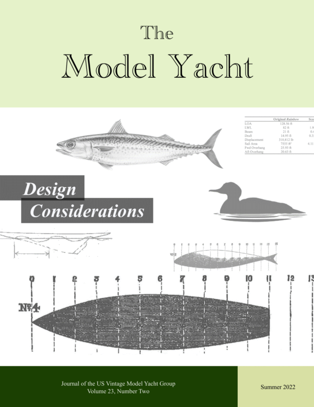
Summer 2022 The Model Yacht The Model Yacht is published three times per year by the US Vintage Model Yacht Group. Copyright 1989 to 2022 by the US VMYG. Reproduction for noncommercial purposes permitted; all other rights reserved. Other copyrights are maintained by the original holders, and such material is used here under the fair use provisions of the relevant copyright acts for nonprofit research and educational purposes. Editorial Address: John Stoudt 309 Sundance Drive Chester Springs, PA 19425 On the Cover: To try and attain optimal model yacht configurations, designers have turned to everything from numbers to nature. Learn more about a full scope of design considerations in this issue. Membership Renewals: The annual membership fee will be due and should be renewed with the publication of the first journal of the calendar year. Please reference “Membership” on page 34 for dues amounts. Please use the form that accompanies this issue of The Model Yacht to complete your membership renewal. Requesting a sail number: The easiest way to request a sail number is to go here: https:// usvmyg.org/registration/ Then click on the class of the boat you wish to register and get a sail number for. A form will open. Complete the form, pay the fee, and everything will happen automatically. You will receive a number, issued by the class coordinator. The Layline By John Stoudt Definition: A layline is a straight line (or bearing) extending from the next mark to indicate the course a boat should be able to sail on the one tack in order to pass to the windward side of the mark. (vsk.wikia.com/wiki/Layline) US VMYG 501(c)3 The vintage group is taking steps to become a nonprofit organization. We are using LegalZoom to guide us through the process. The pursuit of the development of The Model Yachting Center has led us here. There were two individuals who each contributed enough money to enable the group to pay the fees associated with this effort. Our treasurer is maintaining a separate line item for the income and expenditures made for the nonprofit effort. This will be identified when we report the annual budget each year. Board of Directors Part of the requirements of obtaining nonprofit status is to appoint a Board of Directors. I recently appointed the following individuals to the board who will serve along with me as we move forward. The board will meet every six weeks to assess where we are and where we need to go. They will review the budget, membership, membership benefits, social media platforms and how we can work more efficiently and effectively. Board of Directors • John Stoudt, President • Chuck Lage, Secretary • Tom Alessi, Treasurer/Membership • Jeff Beck, Managing Editor/Web Master • Ken Young, Coordinator The Board’s purpose is to lead, set direction, and make timely decisions on behalf of the US VMYG. The Board will be selecting and appointing an ad hoc committee to spearhead the effort surrounding The Model Yachting Center. We are looking for names of individuals who would be good committee members, who understand model yachting and its impact on large boats, the larger yachting world, and have contacts in appropriate places. 1
Summer 2022 The Model Yacht Inside The Leadership Team……….i The Layline…………………1 Log Canoe Project John Henderson has been leading an exciting project to develop a model log canoe. If you have ever seen a log canoe sail, you will understand why this is not an easy project. Read more starting on page 8. A few individuals have been building log canoes from John’s plans including Stanton Smith. Stanton has come up with another concept, that of building a subdeck that will enable an open cockpit boat to stay afloat. Follow his effort starting on page 15. Barnacles…………..14, 27,32 Model Yacht Design Issue 23-02 (this issue) Chesapeake Bay Canoe…..…8 This issue is loaded with some wonderful articles. The one written in 1896 on page 4 is a fun read and has answered many questions that I have wondered about regarding hull shape and model yacht design. The author is no relation to Ivor Walton, so Ivor tells us. Modeling an Open Cockpit Upcoming Issues in 1896…….………….…… 4 Modeling a Historic Boat Using a Raised Floor…15 Modeling the J-Boat Rainbow for the Vintage 36/600 Class: The Challenge of Scale……18 Running Back Stays..…..… 22 Tech Topic: Speed…………25 Model Yacht Construction and Restoration Classes.…. 28 Marblehead Class The next few issues are shaping up. One on fittings will address how to make your own brass and aluminum fittings. We get a lot of requests from individuals to identify boats. We will attempt to build an issue around the email conversations we have had regarding boat identification. We will remove extraneous stuff, make them readable, and include photographs of the boats and their details. Sailing and tuning of vintage models can be more challenging than other model yachts. We will attempt to assemble information that you may find useful and to help improve your thumbs. Remember to let us now if you would like to write something or know someone who would. Rig Plan………..………… 30 Membership Getting the Ballast Casting Right………….………….. 33 US VMYG Membership…..34 The board would very much like to grow our membership to enable us to help preserve the history of model yachting. On our Facebook page we have well over 800 viewers. We have around 230 members. How can we get some of these individuals to join the US VMYG? We would love to have your thoughts and ideas. 2
Summer 2022 The Model Yacht 2022 National Regatta The Chester Springs Model Yacht Club is hosting the US VMYG National Championship Regatta again this year. Those of you who joined us last year know how much fun you had in 2021. Well, we are going to give it a go again. Sign up early to ensure you are ready for the event. You may register here: https:// form.jotform.com/220725598101958 United States Vintage Model Yacht Group 2022 National Championship Regatta Dates: October 7 – 9, 2022. The sailing location: Tel Hai Camp and Retreat Center 1101 Beaver Dam Road, Honey Brook, PA 19344. The NOR can be found here: https://usvmyg.org/wp-content/uploads/2022/03/USVMYG2022NOR.pdf 3
Summer 2022 The Model Yacht Model Yacht Design in 1896 Diana This is an excerpt from Model Yachts and Model Yacht Sailing – How to Build, Rig and Sail a Self-Acting Model Yacht by James E. Walton. Chapter 1 is a wonderful description of how the author went about the process of model yacht design given the various factors involved and how he solved them. The editorial staff found this a fun read and wanted to share it with you. The entire book is available as a reprint. A search will find it for you. Chapter 1: Principles of Model Yacht Building In order to ascertain the best lines, i.e. shape, for progression through the water, Nature herself may, without hesitation, be taken as the best teacher, and amongst fast-moving fishes a mackerel is one of the fastest and most graceful. taking the shape back upwards, and next sideways, and in harmony with these lines all the vessels mentioned in this work are constructed. On looking at the diagram of the mackerel it is at once apparent that a clean run is more important than a sharp entrance, for the drawing shows the fish to be much fuller in the fore than in the after part; I procured a mackerel, carefully measured, and drew it to scale (see Diagrams 1 and 2), first Diagram 1. View of Mackerel—Back Upwards. Length of fish: 13 in (in 1-in divisions). Diagram 2. Side View of Mackerel (actual measurement, in inches). 4
Summer 2022 The Model Yacht bearing this in mind, and having drawn the mackerel in divisions of inches, I took the forward eleven divisions as a model for the deck and general lines of my vessels —first, so far as regards “going through the water”; secondly, because I should thus get “the widest part or beam amidships,” and as near the centre of motion and gravity as possible. Diagram 4. Deck Lines of Mermaid (actual measurement: 31 in overall, 4-in depth, 2-in counter). with the increased beam, she had 5 lbs. lead keel, and was rigged as a cutter (see “Diana” for cutter rig, frontispiece), schooner, or lugger at pleasure. I found she beat Seashell considerably in any wind, but especially in strong winds, sailing under any of the above- mentioned sails. Diagram 3. Deck Lines of Seashell (actual measurement: 31 in overall, 3-in depth, 2-in counter). With these ideas in my mind, I constructed Seashell (Diagram 3), with the actual measurements there stated (as is the case on all the drawings). I rigged her as a schooner; thus— Diagram 5. Deck Lines of Silver Spray (actual measurement: 31 in overall, 5-in depth, 2-in counter). Learning by this that increased beam and weight meant more power, more sail, and greater speed, I then made Silver Spray (see Diagram 5), with 8 lbs. keel, and nearly 2 in. more beam than Mermaid, and in this vessel I reached about the proportional beam that most model yacht builders have adopted, viz. 3 1/2 beams to the length. I rigged her as a cutter only, and she easily beat Mermaid every way, I also discovered that cutter rig was best, the boats under this rig sailing faster and truer, and are more quickly and expeditiously managed; at the same time, I discarded fixed rudders for reasons stated before. She sailed well and steadily and could be made to go in any direction in a light breeze, but her narrow beam and lightness, with only 3 lbs. keel, rendered her useless in a stiff breeze, except when she was running away from it. I next built Mermaid (see Diagram 4), with nearly 2 in. more beam, and exactly to the measurement of the mackerel sideways, simply increasing each line in proportion as the ship was larger than the fish; all the lines of the hull being of course in harmony With this model, Silver Spray, I had reached a point at which I stuck for some time; I could hardly think still increased beam or depth would be an advantage, yet I wished to progress, and try something I would. 5
Summer 2022 The Model Yacht “up and down”, prevents her making so much leeway. I thought the matter over carefully, and at last arrived at the following conclusions: A fish goes through the water only, but a ship goes through and over. Now a duck goes over the water; how would a vessel built upon a combination of fish and duck succeed? No doubt there is a limit to the breadth of beam, and although I have not yet fully experimented, I am inclined to think that the limit is reached in Diana of three beams to the length. I got a duck, took a plaster cast of his under side, noticed the way ducks got over the water, the resistance of the water and the ripples and wake caused by the duck’s motion over the water, and I decided to make a ship to go over the water rather than through it; the top of the water is alive, and easily displaced in any direction save downwards, the deeper one goes the stiller it is, and the more difficult to displace. I considered, therefore, if I built a vessel of greater beam, very light draught of water, with a lead keel below the bottom, I should get greatly increased power and speed, for I felt satisfied that the light draught and larger sails more than compensated for a wider beam. On this I built Golden Crest (see Diagram 6), with these qualities, beam 10 1/2 in., or 1/2 her length exactly, and only a bare 4 in. depth, and 10 lbs. lead keel; I fitted her with sails as a cutter, making them larger than those of Silver Spray, in proportion to her increased beam and ballast (in lead keel), and she more than fulfilled my utmost expectations, for she beat all the three former models out and out, both in speed and steadiness. Still, however, I had not quite finished my experiments, for I remarked that in strong winds Golden Crest, on account of her low freeboard (i.e. little height out of the water), was sometimes overpowered sooner than I thought she ought to be, and I determined to build another vessel on the same lines and of the same size exactly, but with 1 in. deeper hold ; this I did in Storm Along (see It stands also to reason that a vessel of a wide beam does not heel over to leeward so much as one of a narrower beam, and it results from that—1st the sails being more perpendicular to the wind, have more power to propel; and 2nd, the keel being also more Diagram 6. Deck Lines of Golden Crest (actual measurement: 31 in overall, 4-in depth, 2-in counter). 6
Summer 2022 The Model Yacht Diagram 7. Deck Lines of Storm Along (actual measurement: 31 in overall, 4-in depth, 2-in counter). Diagram 7), the only difference between this and Golden Crest being the 1 in. extra depth of hold; lead keel, sails, masts, &c., &c., all were exactly the same. the victor; in light winds by very, very little, but in strong winds the greater buoyancy, and therefore lateral power, of Storm Along always carried the day. Now, when Greek meets Greek, then comes the tug of war. So, it was here, and only after numberless trials in all winds, and finally by interchanging sails, that Storm Along proved the winner; the reason this was difficult to establish was that at first, I only sailed each with its own sails; when the wind was moderate and sea smooth Golden Crest won a little; on the other hand, strong breezes and sea on, Storm Along won. With all these ships there are no bulwarks, no ornaments, or projections of any kind, nothing but the gear, &c., necessary to set the sails and work them; everything else is not only useless, but mischievous lumber. It may be remarked that the whole of those boats when running before the wind, with self-acting lead rudders, run at very nearly the same speed, length to a great extent governing speed; but on turning to windward, each falls into its place, as assigned to it in the foregoing pages. I interchanged their sails, and Storm Along won considerably always. I then found I had happened to lace the feet of the sails of Storm Along to their booms, but it never struck me such a trifle would interfere much with the sailing of a model: I was mistaken, however, for I found whichever had the laced sails was sure to lose, and Golden Crest lost most; mind, all these experiments were conducted on the open sea for hours, with true winds and true sea (the most perfect test). I cut the sails loose, and at once and ever after, Storm Along proved invariably I have not yet tried whether greater beam still than 1/3 the length is an improvement; I am resting on my oars awhile, and perhaps someone else may undertake the experiment. Walton, James E. Model Yachts And Model Yacht Sailing: How to Build, Rig, and Sail a Self-Acting Model Yacht. John Bateman & Company, London. 1896. 7
Summer 2022 The Model Yacht Modeling a Historic Chesapeake Bay Log Canoe Article and photographs by John Henderson L Magic on its initial sail. The wind was around 7 knots with gusts to 10 knots. adze, and hatchet were the preferred tools. There were 3-log, 5-log, 7-log, and even 9-log boats built this way. This overly simple summary belies the complexities of the actual construction, such as the forming and shaping of the ends, the determination of thickness, and (at least in some parts of the Chesapeake) the addition of “risers” to form the topsides. The building process is well-documented in references like M.V. Brewington’s book Chesapeake Bay Log Canoes and Bugeyes. og canoes were work boats on the Chesapeake Bay, earning their living tonging for oysters, crabbing, and any other profitable activity their watermen owners could devise. They were, literally, built from logs. Their origins are found in the dugout canoes of Native Americans, but by the 19th century European settlers had enlarged the canoe design by fastening an odd number of logs together side-byside, carving the outside to a pleasing double-ended shape, and then hollowing out the interior. Broadaxe, 8
Summer 2022 The Model Yacht Despite their workboat origins, by 1840 there were organized races among the log canoes, and construction of lighter and presumably faster canoes began. The Civil War ended these races. There were sporadic revival efforts, culminating in the formation of the Chesapeake Bay Log Canoe Association in 1933. Racing began again; boats were restored to “better than original” condition, and sail plans grew larger and more innovative. Enough of these log canoes survive to this day to form an active racing fleet. I think most are of the 5-log size and are documented for historical records. The originals were built “by eye” with no drawn plans, and it is not unusual for there to be variations between the two sides. The documentation process includes creating lines drawings by taking measurements off the original hulls (presumably the preferred side of the hull). Sail plans seem to have evolved constantly and grew larger as racing became a priority, so documentation of sail plans is pretty “generic.” The boats had and still have centerboards, but these are rarely documented in the historical record. In fact, one of the few drawings that I found that showed a centerboard had a footnote saying that the location of the board was not accurate. Over the years of racing, centerboards evolved to be ever-deeper and better-shaped. Although this is an exciting way to spend an afternoon, I didn’t see a practical way to implement this in an R/C model, to say nothing of the starting line chaos caused by a boat with long boards sticking out the side. Therefore, this model has a deep fin with a ballast bulb, and the large prototypical cockpit must be sealed reliably when sailing. There is a downside to ballasting. Full-size unballasted log canoes may capsize, but, unlike inadequately sealed ballasted models, they do not suffer the indignity of actually sinking. Full-size boats cannot be self-rescued after a capsize; sails and masts must be removed before the hull can be righted. Each racing canoe is accompanied by at least one chase boat. The model that is the subject of this article is based on the log canoe Magic, built in 1894. It is documented in the Maryland Historical Trust State Historic Sites Inventory. This documentation includes a description of the boat and its construction, along with a set of lines drawings and a generic log canoe sail plan. Magic is also documented in M.V. Brewington’s book, which contains considerable historical information on these boats. Magic is still raced today, carefully restored and maintained. The canoes are unballasted and have enormous sail plans. They are kept upright (at least most of the time) by a large crew sitting out on long hiking boards that are moved from side to side with each tack (see Fig. 1). Hiking boards have been in use on log canoes since the mid-1800s. Fig.1. Magic in current racing form. 9
Summer 2022 The Model Yacht The sail plan in Fig.1 is considerably taller than the generic plan documented in the historical record, consistent with how these boats have evolved in the early 20th century. My model, for reasons of stability and lack of courage, has a lower aspect ratio rig, which could be viewed as a compromise between the original and the current rigs, and it is likely representative of a rig at an earlier stage of evolution. The model’s major dimensions are: Length on Deck: 49 ½ in Sparred Length: 6 ft 2 in (jib boom to boomkin) Waterline Length: 46 ⅜ in Beam: 10 ⅜ in Draft: 18 in Sail Area: 1420 in2 My lines drawings of the model are shown in Fig. 2. The most dramatic departure from scale is, of course, the fin and 10-lb ballast bulb. Hull volume had to be increased enough to provide the extra displacement. The increase was not as great as this statement might seem, however, because the full-size canoe has to carry almost a ton of crew (see the photo in Fig.1). The fin is 18 in deep to provide enough stability for at least moderate breezes. While this model is intended to sail in a reasonable range of conditions, I do not suggest that it is ideal for windy conditions— and neither are the full-size prototypes. Fig. 2. Lines drawings for the model log canoe Magic. The scale is approximately 1:8.5, yielding a model that is 49.5 inches Length on Deck. The hull is scale above the waterline to preserve appearance when sailing. Below the waterline, I have deepened the hull to provide more displacement. This departure from scale is almost always necessary in order to make a model that can sail well. I have documented examples of the scaling and design processes in several articles in this journal, and there is also a summary in the Design Articles section of the US VMYG website (see the series “Planning and Building Scale Models that Sail” at https://usvmyg.org/design-articles/). 10 This article is not intended as a construction guide, although the plans are entirely sufficient for an experienced modeler (and one of the author’s friends has built his own model log canoe based on these plans). Nevertheless, I will offer a few comments and suggestions for dealing with some of the oddities of log canoes and especially R/C model log canoes. Rather than carving a hull from an assembly of large blocks of wood, I chose to build a strip-
Summer 2022 The Model Yacht Fig.3. Planked hull. planked hull over plywood bulkheads from which the center sections were removed to create ring frames. This is not an unusual modeling practice. large opening in the bottom. Fig. 4 shows the boat with the deck installed. The side decks on my model are wider than scale in an effort to discourage flooding when the boat heels. Even with the wider deck, the cockpit opening is very large for a model, and it must be sealed effectively when sailing. I note in passing that full-size log canoes carry a designated “bail boy” (typically a young, small person who aspires to more glamorous crew roles in the future but whose services are vital in keeping the canoe afloat). The rectangular holes on the deck’s centerline fore and aft of the cockpit are for the masts, allowing adjustment of the position of the Center of Effort of the sail plan. A prominent feature in Fig. 3 is the centerboard trunk and its support. The slot visible in the top cap of the trunk is for the keel bolts that will hold the fin. The trunk is longer than the profile of the fin in order to allow for adjustment of the Center of Lateral Resistance, if necessary. This is also noted on the plans in Fig. 2, and it was inspired by the lack of documentation of the prototype centerboard location in the historical record. Early test sails have indicated that the location drawn on the plans is pretty good. I expect to fill in the empty space in the trunk to reduce drag from the Fig. 4. Deck installed. 11
Summer 2022 The Model Yacht Fig. 5 shows the deck with the bowsprit and boomkin installed. The boomkin is the structure on the stern, which projects well past the rudder. A crew member sits on this frequently very wet perch (see Fig. 1) to manage the aft sail. airfoil shape. Having sail area below the sprit means that these sails are “self-vanging.” Most log canoes attach the forward ends of the sprits to the masts with an adjustable “snotter”, which can set the draft of the sail by pushing the sprit aft. The jib is attached to the bowsprit with its boom projecting forward of the attachment point at the end of the bowsprit, in a manner used by most model classes. Fig. 5. Deck with bowsprit and boomkin. The fin is fairly deep (18 in), it must support 10 lb of lead at the bottom, and it must do so without much bending or twisting. I made it entirely from wood. I settled on the structure shown in Fig. 6, which shows the fin’s top edge and its construction. There is a fulllength central spar made of pine—the two pieces of pine have the distinctive end grain pattern. Forward and aft of the pine are lengths of balsa (whose end grain appears as dots), shaped to form the foil. This foil shape is wrapped with good-quality 1/16-in plywood. A leading edge is shaped from paulownia or some other light wood. The result is very stiff; it weighs around 0.7 lb. The profile shapes of the sails (known as “leg o’ mutton”) and the associated nomenclature are unusual, maybe unique to the Chesapeake Bay. The sails are named schooner-fashion: starting at the bow, the names are jib, fore, and main.Yes, the “fore” is bigger in area than the “main.” The fore- and mainsails do not come to a point at their clews. Rather, their aft edges are more or less parallel to their masts and are supported by being lashed to a vertical spar known asa “club.” The booms are called “sprits”, andthey are usually made with some curvature to allow the sail to assume it’s Fig. 7. Foremast snotter. Fig. 6. Structure of the fin. 12 Early log canoes had unstayed masts. Starting around 1930, foremasts acquired stays, but the main (aft) masts remain unstayed even today. The model follows this practice.
Summer 2022 The Model Yacht the chosen hole in a wooden beam on the keel. At deck level, I set the position with a combination clamp and mast collar. The parts and installation are shown in Fig. 8. The wood block goes below deck; the collar is clamped to this block by the screw. The mast goes through the square hole in the collar, and its position can be set anywhere along the deck opening. This provides the necessary adjustment in a lightweight and straightforward way. The radio installation is fairly standard and is made somewhat easier by the huge open cockpit. I used a drum winch with a loop of line that runs around the cockpit from one side of the winch to the other. No return spring is required, and sails can be connected to either side of the loop. All three sails are adjusted together, but there is a separate “trim” servo for the jib. Fig.8. The mast collar allows the mast to be adjusted in both position and rake. The parts are shown in A, and the installation is shown in B. The masts are adjustable in both position and rake and are both keel-stepped. The bottom of the mast is anchored by a pin inserted into The large open cockpit is a concern in the event of a knockdown, so a secure and watertight hatch is required. I like to carry models using the cockpit edge as a handle, so I wanted a hatch that could be inserted with the boat in the water. I have made a big, cockpit-shaped “plug” with slightly tapered sides and ⅛-in weatherstripping foam that can be inserted tightly (I hope) at dockside. Incidentally, the boat can be heeled to about 45 degrees before water reaches the cockpit coaming. The Log Canoe plans are available at: https://usvmyg.org/store/ plans/schooner/ Fig.9. Radio Installation. The trim server for the job is visible on the port side of the centerboards trunk (the bow is to the right in the picture). 13
Summer 2022 The Model Yacht Acknowledgements Fig. 10. The finished model on its stand. Plywood for Decks—Cherokee Wood Products sells I want to acknowledge the contributions to this project made by several of my friends and fellow modelers of vintage boats. Stan Smith, who has won multiple Craftsmanship Awards at the Vintage Nationals, built a log canoe to this design simultaneously with my build, and he and I shared many long and detailed discussions to try to resolve the unique building and rigging issues that never stopped appearing. Rob Dutton and Gary Nylander, in addition to their R/C modeling skills, have been part of racing crews on full-size log canoes, and they provided very valuable insight into the rigging and sailing oddities of these boats. Ed Thieler is recognized as a superb scale modeler of workboats of the Chesapeake and Jersey shores, and he shared his knowledge of log canoe rigging and workings. If there are bad design choices despite the guidance of these experts, those errors are mine. Barnacle 60- by 60-in sheets of Baltic birch plywood cut to size. It is not aviation grade, but this is not a problem for a model yacht deck. The grade of the plywood is B/BB and it is assembled with waterproof glue. This plywood can be cut down to five 12- by 60-in pieces (or any number of other sizes) which gives you pieces large enough to deck a Marblehead without any seam. The “B” grade works fine as there are only one or two small blemishes in that face. Just apply two coats of epoxy to the surface that will be up, sanding between coats and after the second coat. Then apply your favorite finish. And the best part is that they are inexpensive and do not charge for the cutting process. You can go to the link below to look at the description and cutting options. https://www.cherokeewood.com/store/1-8-baltic-birch-plywood-cut-to-size/ 14
Summer 2022 The Model Yacht Modeling an Open Cockpit Boat Using a Raised Floor Article and Photographs by Stanton Smith When John Henderson and I decided to model Chesapeake Bay Log Canoes, we needed to solve the problem of keeping the boat from sinking in case of a knockdown or multiple waves breaking over the boat. Log canoes are open centerboard boats with relatively small decks, so taking on water could be disastrous. John took the approach of building the boat with a larger deck than the prototype (see “Modeling a Historic Log Canoe”) and then sealing the cockpit with a sailing hatch. I chose to build in a raised floor to seal off the majority of the boat, while still giving the illusion that the boat has an open cockpit. Chesapeake Bay log canoe model. There were three things that had to be considered before construction. 1. the size of the sealed compartment under the floor of the cockpit so that the boat would float with the open part of the cockpit completely flooded with water. 2. how the water shipped into the cockpit would drain, 3. how to seal the raised floor from water intrusion. 15
Summer 2022 The Model Yacht The weight/displacement calculation confirmed that the boat would not sink with the cockpit flooded; how to drain the flooded cockpit became the determining factor for where to locate the floor. My initial plan was to use the centerboard trunk to let the water drain. The centerboard trunk height was placed just below the deck level with the raised floor located 1/3 of the distance from the deck to the waterline (LWL). After the floor was installed, a drain hole was drilled in the centerboard trunk to let the water drain from the flooded cockpit. Sail testing proved that this was insufficient drainage, and I added scuppers just above the raised floor. The scuppers at the widest point in the boat work very well and drain a flooded cockpit quickly both upwind and downwind. I am starting a Herreshoff 12.5 model using the same raised floor and sealed tank concept. The primary design consideration for this model is not sinking when the cockpit is flooded; water will be removed from the cockpit with a bilge pump. The volume of the total sealed area will also be double the volume below the waterline, so the boat should float fully flooded with water. Determining the location of the raised floor to prevent sinking In theory a boat should not sink with a sealed air tank created with the floor (top of the tank) located at the LWL because the volume of the tank will be equal to the volume of the water displaced. So a model with a raised floor that runs the length of the boat at the LWL will float the boat awash at the surface. There is some additional buoyancy with a wood boat, but not with a fiberglass boat. For the log canoe model, I added a raised floor about 2 ¼ inches above LWL and sealed the first two and last two sections from the deck to the raised floor. Rough calculations of the increased volume above the LWL created by the raised floor, plus the forward and aft tanks increased the sealed tank volume from supporting the 16 lb of displacement to doubling that sealed tank volume to support 32 lb 2:1 safety margin from sinking. This could be confirmed more precisely using the Simpson’s Rule method to find the volume. See John Henderson’s article on the Simpson’s Rule method for calculating displacement on the US VMYG website at https://usvmyg.org/designarticles/ for how to do this and for the section requirements. The cockpit drains through scuppers placed amidships. 16
Summer 2022 The Model Yacht Building the raised floor The floor location should be determined before the frames are laid out and cut. Although floor beams could be added later, I chose to include them in the frame design. I raised the floor 2 1/4 in above LWL at the center of the boat and 3 in above LWL at the ends. This allows water to accumulate at the center of the boat where the scuppers are. Once the frames are cut, the construction of the hull is normal plank-on-frame construction. Frame construction with floor supports, limber holes and open area underneath the raised floor. Raised floor under construction. Once the hull is completed, sealed, and leak checked, it is ready to receive the raised floor. The raised floor should be installed and leak checked before installing the deck. I put the R/C equipment under the raised floor, so I added two hatches: one for the servos that is sealed with a rubber gasket and screwed in and one for the battery and switch that is easily removable. Once the raised floor is sealed and checked for leaks, the deck can be installed. I installed all of the fittings with either silicone or epoxy on the screws to ensure a minimum amount of leakage. All of the frames have limber/drainage holes and are open underneath the raised floor from bow to stern so that a single plug in the bow will drain the boat and allow air to circulate with the hatch open. Rather than trying to fit the floor around all of the frames, I added a false floor piece for each section. I added 1/8-in square supports around each section area. A good fit of each floor section is important with no gaps and no raised areas. I used weights to ensure a tight joint and epoxied the underside of the floor to seal it. In summary the raised floor allows for open cockpit boats to be modeled and sailed even on windy days. The log canoe has over 1400 in2 of sail area and doesn’t have a lot of beam, so knockdowns occur. This raised floor approach at a minimum keeps the boat from sinking, and in most cases allows the boat to keep sailing. 17
Summer 2022 The Model Yacht Modeling the J-Boat Rainbow for the Vintage 36/600 Class: A Challenge of Scale Text and photographs by John Henderson Fig. 1. Vintage 36 Rainbow Lines Drawings. J-Class yachts always attract interest. They are simply beautiful. They are also huge—typically around 130 ft long. I was challenged to make a semi-scale interpretation of the J-Class Rainbow in a Vintage 36 size. The model had to preserve the above-waterline appearance of the original hull, it had to have a sail area at least close to the 600 in2 of the V36 class, and it had to sail satisfactorily in at least moderate wind conditions. In previous articles in The Model Yacht (Spring 2021, Spring 2019), I have described my scaling of Rainbow down to about 6 ft overall length. I have also described the scaling process in somewhat more detail in an article on creating a Vintage 36 from a favorite Vintage Marblehead design (Spring 2021). The process to design a 36-in version of Rainbow is the same, but the magnitude of the scaling and J-Boat design characteristics made the task more difficult. One of the distinguishing characteristics of JClass yachts is long overhangs at bow and stern, which result in a relatively short waterline length. Since the real size of a boat is represented better by its waterline length than its overall length, we recognize from the outset that this will be effectively a small boat among V36 designs. The original Rainbow was 128.56 ft long. Reducing this to the required 3 ft results in a scale factor of 1:42.86. As explained in previous articles, straightforward scaling will create linear dimensions reduced by this factor, sail area will be reduced by the square of this factor, and displacement will be reduced by the cube. 18
Summer 2022 The Model Yacht The Table below shows key dimensions of the original boat compared with their scaled dimensions. It also shows some of the compromises to make a practical sailing model. The Table reveals some necessary implications and consequences of scaling. As required to preserve above-waterline appearance and to meet V36 rules, the LOA is 36 in and the LWL, beam, and overhangs are close enough to scale to be a reasonable representation. I acknowledge some compromise in slightly shorter overhangs and slightly wider beam— we really need to gain some volume for reasons I will discuss next. The biggest problem is displacement. A truescale displacement of ~4 lb is clearly not going to make a practical V36. Ballast alone is typically more than 4 lb in a V36. Most V36 models of similar profile (full keel, less than maximum allowed draft) have displacements in the 9-lb range. Doubling the displacement requires doubling the underwater volume. Scaling the sail area produced a curious result—the scale sail area worked out to be almost exactly the 600 in2 of the V36 class specification. Actually, this is more worrisome than fortuitous. Scale models (with scale sail area) are almost always over-canvassed (some exceptions might apply in the case of models of work boats), and full-size J-boats were known to carry excessive sail area. This observation leads to the need for more draft and ballast, reinforcing the underbody requirements already noted. The plans for this Rainbow 36 are available on the US VMYG website within the Vintage 36 plans offerings. I have reproduced a small-size version in Fig. 1 on the previous page. For those more accustomed to real, 3-D views of models rather than lines drawings, Fig. 2 shows the as-built result. For comparison, Fig. 3 shows the lines of the original, full-size Rainbow. A true-scale draft of 4 in is also impractical. Referencing similar-shaped successful V36 models indicates that at least 8 in of draft would be more appropriate. Fig. 2. Hull Shape. The solution in both cases is to increase the draft and make the underbody more voluminous. Note that it is insufficient simply to increase the depth of the narrow keel fin. The actual underbody itself must be deeper to gain volume (displacement), as the lines drawings show. Fig. 3. Original full-size Rainbow Lines. 19
Summer 2022 The Model Yacht 3) The section drawings reveal how the model is deeper with a higher volume. Not only is the maximum draft greater, but the underbody volume is greater. This shows clearly in the much more “slack” turn of the bilge and the obviously greater area of each section below the waterline. 4) The shapes of the profile and sections were designed to preserve the Longitudinal Center of Buoyancy (so that the boat floats level) as well as the Lateral Center of Resistance. 5) Calculations of displacement, ballast, Longitudinal Centers of Buoyancy and Lateral Resistance, and Center of Effort of the sail plan (and thus mast placement) were performed in accord with procedures described in the articles referenced above. I can report that the model floats on its lines and the helm is balanced. At risk of deeply offending designer W. Starling Burgess, I will describe what I have done to his beautiful lines in order to make a practical Vintage 36 version. If you concentrate on the above-waterlines portions of the profile and sections drawings, you will note that the proportions of the model are quite similar to the original. So, the appearance when floating is preserved. The compromises below the waterline are not especially subtle, but I tried to preserve the character while doing what was necessary to make a model that could sail in a reasonable range of conditions. Enumerating some of the more obvious design attributes: 1) 2) Gone is the characteristic, almost triangular, underbody profile, with the leading edge of the keel forming an almost straight line from the waterline to the deepest part of the keel just forward of the rudder post. This shape simply did not permit enough draft or volume. I replaced it with a much deeper keel, with a fair curve in the profile from waterline to point of maximum draft replacing the straight line. Because changing the profile shape changed the Center of Lateral Resistance of the hull by adding more area forward and potentially affecting helm balance, I made the rudder bigger to compensate. A bigger-than-scale rudder is generally desirable for an R/C model anyway. The underbody, as revealed in the waterlines view and the buttock line, has considerable shape and curvature, especially in the area near the rudder post. It is prudent to include extra frames in this region in order to control the planks as they are bent into place. Fig. 4 shows how the boat was framed. Note that there are relatively few frames in the midship sections, as adequate strength can be achieved with the planking and frames in the photo, and room for servos is at a premium. The extra frames are at the aft end of the waterline. Fig. 4. Framing 20
Summer 2022 The Model Yacht So, getting to the point, how does it sail? First, let’s acknowledge the effects of a short waterline. We are taking a boat that was designed to a waterline length rule and applying it to a class where overall length is the rule specification. Since speed of a displacement hull (such as full-size JBoats and virtually all of our models) is proportional to the square root of the waterline length, a short waterline boat will be slower. On a day with enough wind for models to reach “hull speed” (maximum practical speed as determined by waterline length), this model would likely be slower than Vintage 36 designs with longer waterlines. In conditions of lower wind strength, speed might be more comparable. The increased hull volume and draft likely increases the wetted surface. This is not helpful in light air, but, at least anecdotally based on limited sailing, this effect does not seem huge. Fig. 5. Rainbow under sail. Achieving adequate stability with a V36-sized sail area was a key point of this exercise. I can report that the boat sails and handles just fine in winds up to a moderate range (say 10–12 kts, maybe gusts a bit higher). Heel can be significant, but not alarming, consistent with even full-size J-Boats. I have not taken it into windier conditions, but I expect it would be less than happy. It can sail in wind strengths where gusts cause the bow to submerge going downwind (which is probably the limit to comfort). This behavior is at least partly the consequence of limited reserve buoyancy in the bow of boats with this hull shape, but this is not the only model boat to bury its bow downwind. A Brig might be in order for those who want to sail this boat in high wind. Perhaps more revealing to folks accustomed to looking at boat lines drawings are the shapes of the buttock and diagonal lines. These are indicated on the drawings. The buttock line in particular reveals a rather dramatic curve, caused by the exaggerated underbody volume. For its waterline length, this is a deep and heavy boat (even if its weight is not out of line for a V36), meaning it displaces a lot of water for its waterline length. One would expect boats like this to drag a considerable stern wave at hull speed, and this model does not disappoint in that regard – going downwind in a breeze provides a clearly visible demonstration of the physics involved in wave making. Fig. 5 shows the model under sail in a “light-ish” breeze. Even in these conditions, you can clearly see the bow and stern waves and the single wavelength corresponding to almost the full waterline. The boat is nearing its maximum practical speed. For those who admire the appearance of J-Class yachts and like to see them under sail, this Vintage 36 version offers an affordable and practical sailing model. 21
Summer 2022 The Model Yacht Running Backstays Article and Photographs by Gudmund Thompson My winter project this year starts with Alan Horne’s beautiful Nottingham 60 hull, and, as I want the boat to be a test bed for a number of sail rigs, includes the installation of running backstays. Here is what I have done in the process of setting up the runners. This rig on the left is close hauled and shows a tight runner made up of a 198-cm loop attached to the mast and a 9-cm lead coming from the deck. On the right, this rig is reaching, and the slack runner shows that it needs an extra 30 cm of line to stay clear of the mainsail. Throw Calculation of a reasonably balanced set of sails. This allowed me to calculate (among other things) the amount of line throw that would be required to make running backstays operational. That number, as shown in the sketch, was 30 cm (about 12 in). Because one of the rigs I want to mount will have numerous headsails and gaff mainsail, I sketched the setup in INKSCAPE (a free CAD program) using the dimensions of the hull and my projected dimensions 22
Summer 2022 The Model Yacht need to be augmented by a 4:1 block and tackle system. This was accomplished by mounting a rotating two-sheave block to the servo arm and a three-sheave block to a beefed-up deck support that runs between the two hatches. (This setup also includes an elastic line to maintain the correct orientation of the blocks during the movement of the servo arms.) Programming My normal programming scheme for a yacht with an overlapping foresail (controlled by separate port and starboard sheet servos), is to use a pair of modes in my computer radio to deal with the port and starboard points of sail. I will do the same thing with the Nottingham 60. This view from above the yet-to-be-installed deck shows the rudder servo and the two runner servos with their block, lines and through-deck fairleads. Next, I considered the servos that I wanted to use and chose a location in the hull that allows access to them and their lines. This required a little modification to Alan’s building instructions, but by moving the rudder servo back and down a bit, I was able to get the 35 kg-cm servos mounted directly below the aft hatch in a way that they were securely incorporated into the deck substructure. The next calculation was the size of the servo arm that could be used in this location. This turned out to be about 4.5 cm—any longer and the end of the arm touched the rudder servo tray as it was rotating into the lock position. Finally, in order to get the required 30 cm of throw, I determined that the servo arms would This view from below the deck shows the runner’s lines and servos. 23
Summer 2022 The Model Yacht Starboard Tack Mode foresheets and the running backstays through all points of sail. A two-position switch will select the port and starboard tack modes, and the rudder stick will control the rudder. In this mode, with the apparent wind coming over the right side of the boat and the boom swinging out to the left, the running backstay on the right side of the boat will be in the overlock tensioned position while the runner on the left will be completely un-tensioned as it pays out with the movement of the main boom. (Any tension in this runner will at best cause a crease in the mainsail and at worst, interfere with its movement.) Going from port tack to starboard tack will be achieved by using the rudder to get the boat to maneuver through the wind (either tacking or gybing) and flipping the switch to change modes. If this is done correctly, and without moving the throttle stick, the boat will fall off onto roughly the same point of sail, but on the opposite tack. Port Tack Mode Unfortunately, while the process above may be appropriate for going from close hauled to close hauled, I am seriously concerned about gybing. Here, it could be possible for the tensioned runner to be released before the needs-to-be-tensioned runner is firmly in the overlock tensioned position. The consequence could be a stalled servo (using lots of electricity) and a poorly supported mast—probably not an ideal situation. Here, the opposite is the case. The left-hand runner will be in the overlock tensioned position while the right will be un-tensioned. Overlock—Needed? If anyone has wondered why the servos need to be in the overlocked position when they are being called upon to support the mast, let me quickly run some numbers. The servos are rated at 35 kg-cm, but with the servo arms being 4.5 cm long, the actual output at the end of the servo arm is only 7.78 kg. This 7.78 kg when it comes out of the 4:1 block and tackle, drops to 1.95 kg, or about 4.3 pounds of tension when the servo is rotating, and this assumes zero loss to friction. If, however, the servo arm has moved into the overlock position before the mast needs the full support of the stay, the required tension can be provided by the static positioning of the idling servo in the deck’s superstructure. My solution will be to program my radio such that switching from port mode to starboard (or vice versa) will only be possible when the main boom is being held at (or near) the center-of-boat position by the mainsail sheet. By doing this, the mainsheet will actually support the mast while the runners swap overlock position—the boom needs to pass through this position during any tacking/ gybing maneuver anyway, so this is just a matter of timing. Wish me luck as I move on to other challenges as I strive to complete this great project Sailing While my computer-based transmitter will have many subroutines engaged at any given time, only three radio controls will be needed to manage the yacht. The “throttle stick” will control not only the main sheet, but also the port and starboard More details on this process are available on usvmyg.org under Design Articles”. The author can be contacted at gudmund.thompson@gmail.com. 24
Summer 2022 The Model Yacht SPEED Tech Topics: Article and Illustrations by John Henderson Photos by Judy Bonanno The practical speed limit implied by Equation 1 is caused by wave-making. We have all seen the bow and stern waves and the wakes that our models make when they are going fast. Making these waves requires energy, and this energy loss limits boat speed. The waves tend to get bigger as our boats go faster, with more and more energy loss until our sails just can’t extract enough power from the wind to go any faster. How fast do our models go, really? They always look fast—well, at least mine do— but what answer do we get if we try to quantify their speed? The standard equation for “hull speed” that is often quoted in magazine articles is: (1) Fig. 1 contains three drawings of the bow and stern waves generated by a boat’s motion, and it supports the conclusion that these wave trains change with boat speed. where velocity is given in knots, the Load Waterline Length (LWL) is in feet, and “hull speed” is understood to be a sort of maximum practical speed. Under what conditions is this equation true? How accurate is it? Does it apply to boats of all sizes? Why are speed and length related this way? The first qualifier is that Equation 1 applies to displacement boats. That is, boats that cannot plane or at least are not planing when we apply this equation. “Displacement” means that the boats are supported solely by their inherent buoyancy. They have not risen up on their bow wave as planing boats do. Virtually all of our model sailboats operate in displacement mode. Boats are slowed by resistance, which comes from both “skin friction” and the energy losses caused by making waves. Skin friction dominates at low speeds (light air) and is not the big contributor to the practical upper speed limit described by Equation 1. The conditions that concern this article —losses due to wave making—are found with higher winds and higher boat speeds. Fig. 1. Drawings of the bow and stern waves generated by a displacement boat’s motion. 25
Summer 2022 The Model Yacht boat of “usual” proportions (like our models). The wavelength of the waves generated by the boat’s motion is designated by the Greek letter lambda, λ. Note that, at low speeds (top drawing), the wave train has several waves along the LWL, indicated on the drawing as “λ < LWL.” The number of waves diminishes (and the waves become longer) as speed increases. When λ exceeds the waterline length (middle drawing), the boat’s stern will drop down into the trough (note the bow-up attitude), and the boat appears to be trying to climb up onto its bow wave. A displacement boat is not able to do this with practical power levels. The third drawing shows the wave train when λ and the LWL are approximately equal. This is the speed predicted by Equation 1, which will likely be the practical upper limit to speed in a displacement Before anyone dismisses this discussion as idealized drawings in a textbook, let’s look at some photos of model boats underway. Figures 2 and 3 are photos of the author’s 6-ft model of the J-boat Rainbow, taken by Judy Bonanno at the 2021 Vintage Nationals. Fig. 2 clearly shows the bow wave at the forward end of the waterline and the stern wave aft; it is apparent that one single wavelength is almost as long as the LWL. The boat is traveling at a speed approaching “hull speed.” Fig. 3 shows the wake, and it clearly reveals about three wavelengths of the resulting “transverse” wave train following the boat. This matches the textbook exactly. Fig. 3. Rainbow’s wake and following wave train. Fig. 2. Rainbow with a wave train nearly equal to the LWL. 26
Summer 2022 The Model Yacht wave train; it cannot climb out of this trap without applying more power than our sails can generate. Equation 1, however, teaches us something more quantitative. The speed limit is proportional to the square root of the waterline length. We all accept the idea that big boats go faster than little boats, but why does the speed depend on a square root, and where did the proportionality factor of 1.34 come from? More bad news: Normal sailing yachts probably will not reach this speed except under unusual circumstances. From what I have read, a speed of might be more typical, sometimes even less for beamy and heavy-displacement boats, whose waves, even though the wavelength is given by Equation 1, are bigger. Bigger waves take up more energy and make a trough that is harder to overcome. Dedicated racing boats, even displacement boats, might go a little faster than Equation 1. A factor of 1.45 is claimed for something like a J-Class yacht. To make some sense of this square root relationship and the peculiar factor of 1.34, I will refer to C.A. Marchaj’s book Sailing Theory and Practice. After more physics than would be polite in a family magazine like this one, he presents an equation that relates the speed of propagation of a surface wave in water (v) to its wavelength (λ): For a 4-ft long (LWL) model, the hull speed, using the 1.34 factor, is (only) about 2.7 knots. Sorry. But it still looks fast. λ (ft) = 2πv2/g, where “g” (the acceleration due to gravity) = 32.17 ft/s2 = 0.195v2, when v is in ft/s = 0.557v2, when v is in knots (nautical miles/hour). All of this applies to boats of “normal” shape, which I think includes virtually all of our “vintage” boats. Other shapes, which might make smaller waves, could exceed the speed predicted by the equations above because the smaller waves they generate extract less energy from the propulsion forces. Examples of such shapes would be racing kayaks, rowing shells, catamarans, and other multihulls. It is not that the speed of wave propagation changes, but rather that the light and narrow hulls may be able to “climb” their much smaller bow waves. Planing hulls (when actually planing), including sailing dinghies like the Laser, also exceed displacement hull speeds. Rearranging the last expression yields which is Equation 1 if λ is replaced by LWL (in units of feet). This means that when a boat is traveling at a speed where one wavelength of the wave train the boat generates is equal to the waterline length, then that wave – and consequently the boat – is traveling at a speed given by Equation 1. This is a practical speed limit, because the boat is “trapped” in its own Barnacle The pessimist complains about the wind; the optimist expects it to change; the realist adjusts the sails. ~ William Arthur Ward 27
Summer 2022 The Model Yacht Plan now for 2023: Model Yacht Construction and Restoration Classes Registration for these WoodenBoat School classes opens up on January 2 and they tend to fill up quickly. So if they sound interesting, check out your 2023 calendar now and start planning ahead. boat. An unfinished boat could have a planked deck built and installed, hatch openings framed, hatches built and fitted, spars constructed, electronics installed and set up, or the rig built and installed. A display and travel stand could also be built. And there may even be the chance to establish a waterline and paint the model to your specifications. Pond Yacht Restoration Restore/complete your own pond yacht and get it ready for sailing or display. John Stoudt: June 26–July 2 (tentative date based on WBS scheduling. Date to be confirmed in Nov. 2022 ) There are many models and pond yachts out in the world in need of repair or restoration. A boat may have been a family heirloom, a model you found in an antique shop or at a flea market, or a project that you began but couldn’t find time to complete. If you happen to have such a boat, this week with John Stoudt will present you with the opportunity to evaluate your model and determine a plan for its restoration and completion. The work might include repairing a damaged hull, building a new rig, making fittings, repairing a vane gear, getting the electronics working, installing new electronics, or re-rigging the 28 Students may bring any type of pond yacht, especially those rigged for remote control. Some older self-steering boats could be reconfigured for remote control sailing, or the self-steering mechanism could be repaired. If you have any questions about the boat or model you have, you can contact the instructor through the WoodenBoat School office. John Stoudt will consult with each student prior to the course to develop an understanding of your boat and plan of work. Together you will determine what materials and supplies you will need to bring along and what John will make available. He will have other materials and parts on hand for the unexpected. A final plan for the restoration and/or completion of your boat will be established on the first day of class. Each morning, the students and John will evaluate where they are, how they have progressed, and how to proceed. Come spend a week at WoodenBoat School and develop a passion for models that is both fun and rewarding!
Summer 2022 The Model Yacht Build Your Own Plank-Constructed Pond Yacht A Vintage Marblehead-class pond yacht designed for radio control Bruce Richter: August 27–September 2 (tentative date based on WBS scheduling finalization. Date to be confirmed in Nov. 2022 ) In this course each student will begin or continue working on the construction of his or her own Vintage-class Marblehead pond yacht. The course boat Norumbega was designed by former instructor Thom McLaughlin. Construction of this pond yacht will pleasantly challenge and inform students in planking practices similar to those used in building full-sized boats. Students will make decisions based on blueprints and develop an eye for form. Students who have started construction of their VM model in previous years at WoodenBoat School are also welcomed to participate in this course to finish their boat. This week will be an excellent opportunity for further guidance. This will also provide inspiration to those individuals just beginning their boat and to view firsthand the final steps in construction. During this week, the boats of Week 1 students will be planked, faired, and the fin and rudder will be fabricated. Bruce will also discuss the steps that follow to complete the boat: decking, rigging, electronic installation, and painting. 29
Summer 2022 The Model Yacht Marblehead Class Rig Plan Article, Photographs, and Drawings by John Stoudt A number of people have asked for specific details about how to build a Marblehead class model yacht rig. They would like more information than is generally found on the plans of these model yachts. Here is an attempt to provide that information. In order to complete a rig, one must understand the few constraints that are identified in the Marblehead Class Rules: • Hull Length 50 in +/- ¼ in • Sail Area ≤800 in2 • Materials Based on the period of the specific boat – hull, sails, fittings, etc. • Spar Cross Section ≤ ¾ in diameter • Mast Height ≤ 85 in • Battens MainSail ≤ 4 battens and ≤ 4 in Jib Sail ≤ 3 battens and ≤ 2 in • Height of the jib head stay above the deck shall not exceed 80% of the height of the head of the mainsail above the deck. Tritonia Rig Plan. provided to give guidance to build the rig for your boat. This is meant as an example. Adjustments may have to be made for your specific boat. Standley Goodwin, Marblehead class secretary for many years, once told me that during the Depression someone who was out of work could build one of these boats using scrap materials and very little expense. This is one reason you see so many different Marbleheads. Tritonia is one of those boats. You will note in the photos that the jib and shroud racks and the mast step are long. That is because Tritonia was a freesailed boat, and these fittings needed to be longer to accommodate adjustments necessary for freesailing. Please go to USVMYG.ORG and familiarize yourself with these rules and for more information: https://usvmyg.org/classes/vintage-marblehead/ vintage-marblehead-class-rules/ The Marblehead class is a developmental class; therefore, there are many variations of these model yachts and, of course, their rigs. This rig plan is for a specific Marblehead (Tritonia) and is 30
Summer 2022 The Model Yacht Mast step (center) and shroud racks. Jib rack. Tang. Turnbuckles. Boom Vang. The fittings on Tritonia are both purchased and custom. They are shown in the booklet referenced below and the accompanying photographs. They can be substituted with AJ Fisher fittings (if they can be found), custom made, or fittings from a supplier such as Model Yacht Fittings (http:// www.modelyachtfittings.com/). You will need a jib rack, two shroud racks, a mast step, a backstay rack, five tangs (six with the jumper strut), four turnbuckles (or DuBro, Sullivan, Great Planes clevises and rigging couplers), a spreader, a mast crane, a gooseneck, a jib club, and a boom vang. A jumper strut is another fitting you may wish to consider. Complete deck plan details are often missing from the plan. It is more complicated if a free-sailed boat is being converted to remote control. Generally, these guidelines apply: • The mast step is located directly above the point where the lead edge of the keel meets the hull. • The shroud racks are positioned directly outside of the mast step along the rail (within 1/8 inch) and slightly aft of that position. The lead edge of the shroud rack is set back one half the length of the mast step towards the stern. • The jib rack is located so the forward end of the jib does not protrude past the front of the bow. Additionally, when the rig is set there should be enough clearance to maintain a sufficient slot between the main and jib. This position will be more forward than the jib rack location for a free-sailed boat. • The jib boom attachment point should be 20 to 25% behind the lead edge of the jib boom. • The back stay position will be far enough aft so as not to interfere with the movement of the mainsail as the rig moves from side to side. The back stay should not hit the trailing edge of the mainsail. • The main hatch needs to be aft of the mast step, in front of the main sheet fairlead, and large enough to be able to remove and install the electronics board. • A lazarette cover (rear hatch) may be used near the aft of the boat, centered over the rudder shaft, to allow access to the rudder shaft for servicing. • These boats are designed for the sail plan (rig size) to work effectively. The mast height and sail dimensions were laid out to complement ballast weight, center of 31
Summer 2022 The Model Yacht lateral resistance, center of effort and center of gravity. It is not wise to increase the mast height significantly. It will in all likelihood overpower the boat. You can mathematically find the full-size location of the mast step and sheet exit points by determining how large the sail plan is and calculating the multiplier to use to find the full-size dimension. For example, on the Madcap plan (available at: https://usvmyg.org/store/plans), the deck length on the sail plan is 6.25 in. If you divide this into 50 in you come up with a multiplier of 8. You can then take the distance on the sail plan from the bow to the mast and multiply that number by 8. The location is 2.625 in from the bow on the sail plan. So, 2.625” x 8 = 21” which is the location of the center of the mast step from the bow of the boat. The other dimensions, such as the mast height can be determined in the same way. More information can be found in the booklet Restoring Tritonia: A Vintage Marblehead Pond Yacht from 1934. This is available at: https://usvmyg.org/store/publications/ Jumper. Spreader. Attaching the sail to the mast The main sail is mounted to the trailing edge of the mast using a jack line (rigid wire fishing leader) slid through miniature brass screw eyes (dollhouse items) or 1/16-in brass cotter pins. The wire is slid down the pocket in the lead edge of the mainsail which has notches in it. Cut these notches with a pair of cuticle scissors. As the wire is slid down through the pocket and comes to the notch it is slid through each screw eye or cotter pin. This is an effective method of attaching the sail to the mast and allows freedom of movement of the sail from port to starboard. Mast Crane. Barnacle Beautiful Tools —These are amazing tools both to look at and in price. But WOW! Makers Cabinet makes some of the most beautiful and functional tools we have seen. Treat yourself and take a look! (https://www.makerscabinet.com/) 32
Summer 2022 The Model Yacht Getting the Ballast Casting Right! There is a pretty straightforward way to get the wooden plug to be the right size when you are molding a ballast bulb. You need to determine the volume of the plug, which sounds hard to do for such an arbitrary curved shape – but it is not. Here is how to do it: 1. Cut a rectangular solid from the same piece of wood as you are using for the ballast plug. Note that wood density varies among samples of even the same species, so it is important to cut this reference block from the same piece of wood as the plug. Best practice is to carve your ballast plug out of the block that you have weighed and measured. 2. 3. 4. 5. Article by John Henderson Multiply this volume by the density of lead, which is 0.41 pounds per cubic inch, to get the weight of the ballast bulb in the shape of your plug. An example ballast plug, carved from cedar, is shown in the accompanying photo. The volume of this shape could be calculated, but the weighing and measuring method is simpler. Photo by John Stoudt Calculate the volume of the rectangular block (length ⨉ width ⨉ thickness). All measurements should be in inches to give you a volume in cubic inches. Weigh this rectangular piece of wood. Dividing this weight (in pounds) by the volume you just calculated gives you the density (pounds per cubic inch) of the piece of wood that you are using for your ballast plug. Weigh your carved wooden plug. Dividing this weight (in pounds) by the measured density gives its volume in cubic inches— which will also be the volume of the lead ballast. Fig. 2. Pattern fitted on molding board with mold on the top right. Fig. 1. A finished pattern. 33 Photo by John Henderson
Summer 2022 The Model Yacht Membership Form NAME ___________________________________________________ AMYA # ______________* First Initial Last STREET _____________________________________ PHONE # ___________________________ CITY ____________________________ STATE ___________ CTRY __________ZIP _________ Email Address ____________________________________________________________________ (required) *The US VMYG recommends membership in the AMYA. DUES – emailed newsletter (new members) $30.00 for U.S., Canada, and Overseas DUES - mailed newsletter (we ask current members to help reduce costs - select emailed newsletter) $40.00 for U.S. and Canada $50.00 for Overseas Life Member Contribution in the amount of $ _______________ COMPLIMENTARY MEMBERSHIP – The US VMYG makes complimentary memberships available to museum personnel, school directors, et cetera by email only. If you would like to have a complimentary membership for your organization, please provide an email address for the individual who will be receiving the newsletter and other communication. Organization: _____________________________________________________________________ PREFERRED METHOD OF PAYMENT: You may now join/renew electronically at: https://form.jotform.com/90405575663966/ Mail in membership: You may also send a check along with this form for the correct amount to: US Vintage Model Yacht Group 1 Rampart East Media, PA 19063 NOTE: The US VMYG will not share your personal information with outside parties. November 2021 34


