The Model Yacht is a published three times a year by the US Vintage Model Yacht Group
- Minerva’s Restoration. by Tom Kiley. Tom goes through the process of restoring his Bill Bithell A Boat Minerva. Built in 1950, and signed by Bill Bithell, Tom did a complete restoration and conversion to R/C.
- Friendship Rigged Nottingham: The Sails. by Gudmund Thompson. This is final article in a series from Gudmund on construction of his Nottingham sloop. This one deals with designing, cutting, and assembling the sail.
- 2024 US VMYG National Championship Regatta Report. by Ken Young. Review of the National Championship Regatta held in Vernon Hills, IL with complete results and special awards.
- Skimmer: A New Vintage 10-Rater. by John Henderson. John goes through the process of designing and building a “skimming dish” design Vintage 10-Rater with a detailed explanation of the reasoning behind various aspects of the design.
- Tomfoolery. by John Stoudt. After having his schooner Tomfoolery sink at the national championships, John determined that the force of the water coming over the deck against his hatch cover had caused water to get under the hatch cover and into the boat. He solved the problem by using Glad® Press’n Seal® under his hatch covers.
- Carina: An American Heirloom Built and Raced in England. by Mathew Moeller and Greg Williams. Greg goes through the history of A Class Boat Carina that was sailed by his grandfather in the 1930s. He looks at the development of A Class Boats, also called 6 Metres, in England and the US. Carina was restored and finished as a vane boat.
- Pop Up Manufacturing, Self Righting Catamaran. by John Stoudt. A partially completed catamaran showed up on John’s work bench at WoodenBoat School in 2021. He realized this was something special because it was self-righting. He gives us a detailed explanation of determining all of the electronics involved, and the mechanical challenges of finishing a unique boat.

creamcheese
The Model Yacht Journal of the US Vintage Model Yacht Group Volume 25, Number Three Fall 2024
The Model Yacht Fall 2024 US VMYG Leadership President: John Y. Stoudt*, jstoudt309@gmail.com…………………………………………………………………..(610) 316-8695 President Emeritus: John Snow, jsnowj@comcast.net………………………………………………………………..(978) 594-8521 Treasurer: Chuck Lage*, usvmygt@gmail.com…………………………………………………………………………(484) 682-3091 Secretary: Richard McOrmond*, mcormondrc@gmail.com………………..……….……………….(610) 363-2723 Journal Art Director: Bruce Richter, richterbruce@gmail.com……………………………………………………(917) 575-2221 Journal Editor: Jeff Beck*, beck.jeff@gmail.com……………………………………………………………………..(240) 252-0236 Editorial Staff: John Henderson, jgnhenderson@gmail.com……………………………………………………….(443) 282-0277 Ken Young*, youngrun@sbcglobal.net………………………………………………………………(630) 957-7490 Gudmund Thompson, gudmund.thompson@gmail.com………………………………………(613) 852-0648 Webmaster: Gregg Heimer, gheimer@yellowblueit.com……………………………………………………………(610) 960-2185 Membership: Chuck Lage, usvmygt@gmail.com………………………………………………………………………(484) 682-3091 Regatta Coordinator: Nick Mortgu, mortgu@comcast.net………………………………………………………….(609) 820-0509 Archivist……………………………………………………………………………………………………………………………….Currently Open Awards Coordinator: Rob Dutton, edwin653@aol.com.mortgu@comcast.net………………………………(703) 608-8812 Resources Coordinator: John Y. Stoudt, jstoudt309@gmail.com…………………………………………………(610) 316-8695 Plans Coordinator:………………………………………………………………………………………………………………….Currently Open Historian: Earl Boebert, boebert@swap.com…………………………………………………………………………….(505) 823-1046 Boat Identification: Mike Denest, mjd12k@yahoo.com………………………………………………………………(610) 316-3570 Boat Yard Coordinator: Cliff Martin, Cliff-Martin@comcast.net ……………………………………………….(508) 533-5971 Construction Advice: John Henderson, jgnhenderson@gmail.com………………………………………………(443) 282-0277 Jeff Gros, Jeffreygros48@gmail.com………………………………………………………….(630) 673-2201 Social Media: Chuck Lage, chucklage@yahoo.com…………………………………………………………………..(484) 682-3091 Model Yacht Data Set: Jim Freeze, jrfreeze1@comcast.net,……………………………………………………….(484) 402-3550 Class Coordinators Free Sailed: John Fisher, j sher577@gmail.com……………………………………………………………………….(719) 651-0762 Intl A Boat: Mike Denest, mjd12k@yahoo.com………………………………………………………………………..(610) 316-3570 Schooner: Tom Alessi, usvmygt@gmail.com……………………………………………………………………………(610) 566-9504 Skipjack: John Henderson, jgnhenderson@gmail.com……………………………………………………………….(443) 282-0277 Unrestricted: John Henderson, jgnhenderson@gmail.com………………………………………………………… (443) 282-0277 Vintage 10-Rater: Jeff Beck, v10rclass@gmail.com………………………………………………………………….(240) 252-0236 Vintage 36: Rob Dutton, edwin653@aol.com……………………………………………………………………………(703) 608-8812 Vintage Marblehead: Colin Parker, captcparker@yahoo.com……………………………………………………..(410) 404-3093 Vintage Power: Peter Kelley, pdkelley@sympatico.ca………………………………………………………………..(905) 301-9977 Regional Coordinators Australia:………………………………………………………………………………………………………………………………Currently Open Canada: Gudmund Thompson, gudmund.thompson@gmail.com………………………………………………..(613) 852-0648 European Continent:……………………………………………………………………………………………………………….Currently Open Mid Atlantic: Scott Todd, dscotttodd63@gmail.com………………………………………………………………….(410) 310-2453 North Central: Ken Young*, youngrun@sbcglobal.net……………………………………………………………….(630) 957-7490 North East: Cliff Martin, Cliff-Martin@comcast.net………………………………………………………………….(508) 533-5971 North West: Brian Schneider, schneider560@gmail.com…………………………………………………………….(207) 715-2644 South Central:………………………………………………………………………………………………………………………..Currently Open South East:…………………………………………………………………………………………………………………………….Currently Open South West: Ernie Mortensen, usvmygsw@gmail.com………………………………………………………………(858) 525-5217 United Kingdom: Graham Reeves, graham@reevesmail.co.uk………………………………………………..+44 151 936 1140 *Denotes US VMYG board members fi i
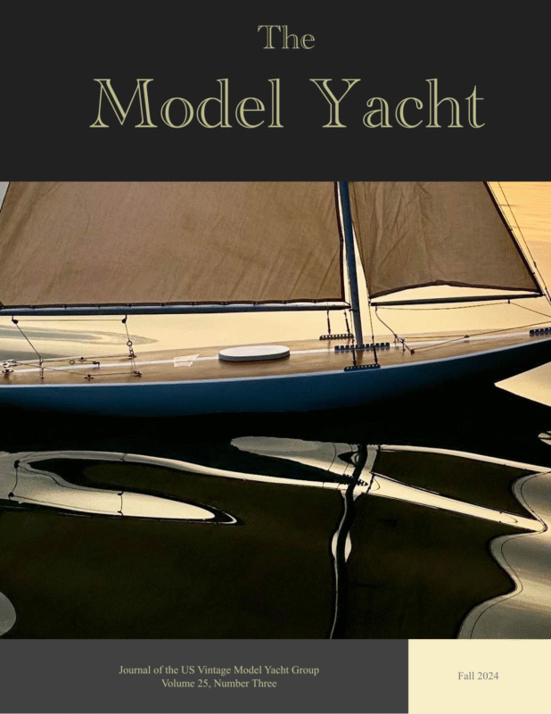
Fall 2024 The Model Yacht The Model Yacht is published three times per year by the US Vintage Model Yacht Group. Copyright 1989 to 2024 by the US VMYG. Reproduction for noncommercial purposes permitted; all other rights reserved. Other copyrights are maintained by the original holders, and such material is used here under the fair use provisions of the relevant copyright acts for nonprofit research and educational purposes. Editorial Address: John Stoudt 309 Sundance Drive Chester Springs, PA 19425 On the Cover: A close-up of Carina, a beauty of an A Class boat first registered in the UK in 1931. Read about its recent restoration on p 30. Photo by Matthew Moeller. Membership Renewals: Membership is now being managed on a rolling 12month period. The annual membership fee will be due on the anniversary of your last payment. You will receive an email notification leading up to your due date. Please see the “Membership” page at https://usvmyg.org/ memberplans/memberships/ for more information. Requesting a sail number: You can get a new sail number or transfer a registration from a previous owner here: https:// usvmyg.org/registration-2/ Select the class to open the correct form. There is a $7.00 fee for new registrations but no charge for transfers. The class coordinator will contact you to confirm your registration and sail number. The US VMYG is a 501(c)(3) corporation. The Layline By John Stoudt Definition: A layline is a straight line (or bearing) extending from the next mark to indicate the course a boat should be able to sail on the one tack in order to pass to the windward side of the mark. (vsk.wikia.com/wiki/Layline) Having just returned from the national regatta outside of Chicago, road weary and having had some success at the event, I write to you again. 2024 National Regatta Three or four years ago Ken Young and I began to explore the idea of holding the national regatta in the Chicago area. When the discussion began there were very few vintage boats in the upper midwest. Now there are. The Photo by Larry Kmiecik Chicago R/C Model Yacht Club Marbleheads drifting across the starting line. members embraced the concept of vintage model yachts. They bought them, built them, restored them, and now they sail them. When Ken revisited the question of hosting nationals at last year’s event, I said yes, and the board agreed. The venue was wonderful, the club’s organizational efforts superb, the weather was beautiful (the wind was a little fluky), and we all had a great event. Where will the US VMYG national championship regatta be held in 2025? If your club is interested in hosting the event, please get in touch with me. There is a regatta reimbursement program to assist the local club with the finances (https://usvmyg.org/regattas/). 1
Fall 2024 The Model Yacht Inside The Leadership Team………..…i The Layline……………….……1 Inside……………………..…….2 Minerva’s Restoration……….…4 Friendship-Rigged Nottingham: The Sails…..…….11 2024 National Championship Regatta Repot…………………15 Skimmer: A New Vintage 10-Rater….……………………21 Tomfoolery…………………….27 Carina: An American Heirloom Built in England..……..…..…..30 Boat Names: Isabelle.….……..34 Pop-Up Manufacturing, Self-Righting Catamaran……..35 Rules The board has a rules committee to manage our class rules and possible changes. The committee gets approached from time to time to make rule changes. We take these suggestions very seriously. Sometimes these suggestions merit further discussion and some lead to slight modifications to a specific rule. Our rules have evolved over time. Each class of boat we support has a different way in which the class and its specific rules have evolved. There are similarities but many differences. We are very careful to maintain the integrity of the US VMYG and its guiding principles and to adhere to who we are as an organization. Changes will not be made based solely on a request from an individual who wants to change the rule to support a personal interest or need. Most rule changes are made for clarification purposes. While we applaud the developmental work undertaken by some, we cannot change the rules to accommodate the needs of individuals over the needs of the whole class. Over the years we have added rules to bring more vintage boats into the fold. These boats needed our support and encouragement to get some of them back on the water. We have added these rules as new classes or as a “group” within a class: 1. Vintage 36/600 (V36s) 2. Unrestricted Class (fit in no other class) 3. Classic Marblehead (1970-1985) 4. Vintage 10-Rater These rules have evolved for well over 100 years, subtly but effectively. We are relatively low-key sailors and do not and are not planning to “measure boats into a regatta”. 2
Fall 2024 The Model Yacht Strategic Planning The leadership team is in the process of going through a strategic planning process. Strategic planning is the process of defining the US VMYG’s direction and making decisions to allocate its resources to pursue this direction. It involves creating a long term plan that is based on our vision, mission, values, and objectives and sets the strategies necessary to achieve them. A report will be provided early next year describing our process and the plan moving forward. Membership As you know our membership is being managed by our website. It is an automated system, maintaining the records of our membership and automatically sending out the notice of renewal to our members prior to the renewal date of your membership dues being due. So, your renewal notice comes to you by email (actually three emails). If you think your membership might be due and you have not received anything from us, please check the spam folder on your computer. Your support is very important to the work we do to support model yachting. Please continue to support the US VMYG. You can go directly to your member login by going here and renew: https:// usvmyg.org/login/ Input If ever you have questions or comments, please feel free to contact us. Our leadership team contact information can be found here: https://usvmyg.org/about/organizational-leadership/ 32
Fall 2024 The Model Yacht Minerva’s Restoration Article and photos by Tom Kiley I have worked or played in full-sized wooden boats most of my life, and I have developed a strong aesthetic for their beauty, simplicity, and design and a good understanding of wooden boat construction. My workplace for many years was one of Maine’s premier yacht yards, which specialized in wood boats, both traditional plank-onframe and modern coldmolded glued-up boats. This lifelong love for wooden boats and my professional experience was truly helpful in this project. But this is Minerva’s story. 42 Bill Bithell’s Minerva sails again.
Fall 2024 The Model Yacht Sitting in the attic for the last 30 years was a classic A Class model built by William Bithell and designed by H.E. Richardson in 1940 in East Boston, MA. My father bought the boat from Mr. Bithell in the early 1950s. Minerva on the cover of Sunday Sailors. She’s 84 years old and a cover girl. And she has thrived on neglect from two generations of my family in an attic for most of her life. That’s not the way to treat a fine old classic lady, a true piece of sailing history and real eye candy. Minerva was built at the end of the pre-World War II pond model era. A 1948 photograph of her is on the cover of the 1998 book by Donald F. Kihlstrom, Sunday Sailors, the go-to book for pond yacht sailing. Minerva in the attic with the original sails. I asked my kids if they had any interest in it. Because this was my Dad’s, I felt the family should have the right of first refusal. No takers, other than “do whatever you want with it”. So I had a decision to make. My thinking went like this: • It is too big and tall to have in the house. • It is too delicate to leave outdoors. • It is too big to fit in most cars and even some small pickup trucks. • It is somewhat of a dinosaur. ⋯ Note the small hatch. So 52
Fall 2024 The Model Yacht • Should I sell it as is? • Should I restore it with modern techniques, finishes, adhesives, and radio control for steering and sails? • Should I donate it to a museum? • Is there something in between? • Which direction did I want to go in? The original jib boom with graduated markings John Stoudt, my mentor and instructor, asked these questions when I mentioned I had a William Bithell A Class model from 1940 that I wanted to restore at his week-long WoodenBoat School Pond Yacht Restoration class in Brooklin, ME. Growing up I had seen many other classes of models, some wood, some plastic, mostly finished in paint. The similar aged wood boats were built in bread-andbutter construction, Minerva being varnished plankon-frame stood out as a uniquely built, light but strong, cutting edge model for her time. What was unique about Minerva was that all of the bits and pieces were still intact. How, I don’t know, as five kids and probably as many as seven golden retrievers lived in close proximity with that model. The vane steering gear is usable still. The original boom with graduated markings and boom vang. In preparation for the class, I had to assess the condition of all components of the project and report by phone and photographs to John. I started work on the model in mid February for a class in early July and the eventual launching/sea trials in late July. The more history I learned about the boat, builder, and designer, the more I realized this boat is very special and needs to be preserved for historical and aesthetic reasons. It was so close to original condition generally, with all the bits and pieces including multiple suits of cotton sails still around (a miracle), I felt it was essential that the model could be returned to the original state for preservation and research. This became my narrative for the restoration. Yes, this is a museum quality model, and when and if a museum is built, she will be donated. Minerva’s original vane. 62
Fall 2024 The Model Yacht The decision was made to restore Minerva from the inside out, leaving the deck on. Upon careful inspection there were no loose frames on the inside, and the fasteners were holding for the most part. The fasteners are brass pin nails which many had turned to a pink dust in several areas because of saltwater intrusion. Other fasteners throughout the boat were OK, and the toothpicks used for deck fastenings were not failing. In the late 1960s my father bought a very early single-channel radio control. He installed it in the boat for steering purposes only. There was no ability to trim the sails. He sailed the boat in saltwater, and, of course, it filled with saltwater and ruined the newly purchased electronics. The second time sailing he had replaced the damaged electronics and had coated the boat exterior with what was believed to be an early epoxy resin in 1969. I remember the cans the resin came in. There were no labels on them and no instructions, so I think it was some sort of a sample or experiment. He coated the outside of the boat with no preparation (the varnish/shellac was still on the boat) so the epoxy had very little chance of penetrating the wood and doing the job it was intended to do. That mistake was a blessing in disguise. When I got the boat down out of the attic in the winter of 2023, that coating came off very easily with a heat gun. As the varnish let go, the epoxy just popped off. I fared the hull with very flexible longboards and a pumice stone that contoured itself to the curves of the hull. I removed the ballast and inspected the bottom of the keel plank. I removed the rudder because it was original and too small for the job under radio control. The restoration began by applying a coat of West 105 resin with 207 special clear hardener. I added a 1.2-oz fiberglass cloth to the wetted-out hull. I could only do one side at a time.There is a 1 ½-in overlap of fiberglass cloth from port to starboard and vice versa to add strength to the stem and central line of the boat. A plastic squeegee eliminated all air bubbles and smoothed the glass out to the contours of the hull. The hull stripped and sanded. The deck was epoxy-coated as well. I did not add fiberglass to the deck because there were no cracks in the wood; the loads are transferred through the chainplates to the centerline of the hull. The mast load is transferred through a compression post under the mast step to the keelson. So the deck is mostly there to shed water. Finishing included multiple coats varnish on top of the epoxy. I used Pettit High Build and Epiphanes clear gloss varnish. The hull in progress. 72
Fall 2024 The Model Yacht I spoke to a couple of model collectors/dealers during my research. A couple of people came to the shop to inspect, appraise, and attempt to purchase the model. One person doubted that it was authentic and thought it was probably a copy/counterfeit Bithell model based on the good condition and light use. At first I could not find his signature, which is often on the inside of the hull on the starboard side. There was a pencil signature and date on the underside of the deck hatch. Skeptics consider this too easy to counterfeit. What I discovered with the iPhone camera was Bithell’s signature, big, bold, and in cursive, on the underside of the king plank. There’s no way this could’ve been a counterfeit as no one’s arm could twist to the shape needed to write a name in that position. Mystery solved! The original deck stripped. The original deck is one sheet of ⅛-in mahogany veneer with holly toe rails for a beautiful contrast. The king plank is Douglas fir; it runs the full length and is ¼ in thick with an ⅛-in rebate to set the mahogany deck in with toothpicks. There are several sawn deck beams for shape and support. Inspection of the inside of the hull was easy with an iPhone camera. I just reached my arm in the hatch and aimed it forward, aft, and up to the underside of the deck. Looking forward. 82 Bill Bithell’s signature on the underside of the king plank after the hatch.
Fall 2024 The Model Yacht Most of the original hardware was still available. The original turnbuckles had seized and corroded badly enough that I broke them trying to free them up. Roger Cousineau of Florida was able to supply me with new turnbuckles, a new mast step for on deck, and a modern gooseneck and boom vang. All but the turnbuckles of the original equipment were still usable, but because of their historic value and risk of breaking. I decided to purchase new hardware throughout. It was pretty short money to preserve the work of Bithel. The Cousineau turnbuckles are identical to what we had originally except that the original hardware was chromeplated. Spreaders were added to the new rig for the upper shrouds, and new lower shrouds go from the spreader base to the deck. I made new mast tangs and hardware from brass sheet stock and purchased new sails from Rod Carr in Redmond, WA. The mainsail is attached by a single-strand wire running through the hem of the luff that weaves through 1/16-in bronze cotter pins set in 5-in intervals down the backside of the mast. This is a very slick and inexpensive way to attach the sail. Although sometimes it is difficult for old eyes and short arms. I replaced the main boom and the jib boom as well. Not because they were lost or unusable, but because they were still original and undamaged by use and time. It would be a shame to break them. Once again, the historic value outweighs the replacement costs. A section of the new built-up mast. I built a new mast to the original specifications but without the deck bury/penetration. I took the advice of John Stoudt and used quarter-sawn pine with a plywood spline set in the aft face. This mimics a track from a distance. I bought a 1 by 8 at a big box store, ripped it to 1 ¼ in, and then planed both halves down to half inch. I took a cove bit (half round) and routed a groove down the middle of each half and then glued them together. When the glue was dry, I ran it through the table saw so that the ⅛-in saw kerf got into the hollow of the mast. Next, I inserted a piece of ⅛-in baltic birch plywood full length into the mast and then tapered the forward side of the mast from the 2/3 point up to mimic a modern wood mast. The new mast weighs 1.39 lb. The original Bithell mast weighs less than 1 lb, a truly beautiful piece of work, very much worth not risking breakage. The new and original rudder. I built a new rudder 50% larger than the original at the recommendation of John Stoudt. Apparently the original rudders are too small for radio-control sailing. Again the original rudder can be reinstalled easily for historical purposes. The new rudder is made from a milled piece of mahogany glued to a carbon fiber tube. I inserted carbon fiber rods horizontally into the 92
Fall 2024 The Model Yacht wood rudder blade to add stiffness and avoid cupping. These pins are also glued through the rudder post. Having had little experience with the old rudder, it’s hard to compare the difference.The new carbon rudder post fits much tighter into the stern tube. A little white lithium grease was added for waterproofing. I launched Minerva in late July 2023 for a test sailing. The photographs included were taken on this first day fresh out of the shop. Everything dialed in quite nicely, and with some minor adjustments everything worked as planned. I was very pleased and proud of the results. We sailed a few more times in the summer and went on to Honey Brook, PA for the 2023 US VYMG regatta and 100th anniversary of the A Class. Minerva came home with a victory captained by Jeff Gros of Yorkville, IL. But more importantly in my mind, she came home with the Earl Boebert prize for craftsmanship and beauty. Minerva racing at the US VMYG National Championship Regatta in 2023. A Class Minerva Specifications: LOA: 72 ⅝ in Beam: 15 in Hull weight: 10 lb Ballast: 30 lb Original mast weight: <1 lb New mast weight: 1.3 lb Displacement: ~45lbs. Waiting to be rigged before the National Championships in Honey Brook, PA. 120
Fall 2024 The Model Yacht Friendship-Rigged Nottingham: The Sails Article and photos by Gudmund Thompson This is the next article in a series detailing the construction of Gudmund Thompson’s FriendshipRigged Nottingham. You can see earlier articles from this series in The Model Yacht: “Below Deck” in Volume 25, Number 1 and “The Deck” in Volume 25, Number 2. — Ed. In this final article of the FriendshipRigged Nottingham series, I will address the final element of the development and building of that boat—the sail rig. Design After researching and examining numerous sail plans in the design phase of this project, I settled on the Friendship rig which I acquired from the US VMYG website under the name Friendship Sloop 1910 in Unrestricted Model Plans. Using the free CAD program Inkscape, I was able to display the rig standing, Fig.1 The left image (from Inkscape) shows the Friendship rig sitting on the Nottingham hull. The right image shows the Lead calculation (10.5%) of one of my many iterations of sail rig, superimposed on the Friendship rig, sitting on the Nottingham hull. 2 11
Fall 2024 The Model Yacht appropriately sized, on the Nottingham hull. I was also able to calculate the area of each of the sails and, using their spatial relationship with the hull’s Center of Lateral Resistance, calculate the Lead of the setup. Once I had settled on the size and shape of each of the sail rig components (gaff-rigged main with topsail, jumbo jib, foresail, and top foresail) I made and attached paper sails to the standing rigging on the physical boat in an attempt to identify any problems. Thankfully, after a few iterations of this process, I was able to settle on a specific set of sails. Construction Next came the task of converting the drawings in Inkscape into actual sails, and for this I turned to another free computer program. Sailcut CAD is a sail design and plotting software that allows you to design and visualize your own sails. This is quite a sophisticated program; it is able to do crosscut, twist foot cut, vertical cut, mitre cut, and radial cut sail designs as well as wing sails, all in a number of languages. It also includes a viewer where you can assemble a hull, a rig and a set of sails to see how they match. The program, while intended to produce full-sized sails, works for me as it is able to output the 12-in wide panels in a format that is compatible with my Silhouette vinyl cutter. Fig.2. On the left is the Sailcut CAD depiction of the five-panel gaff mainsail that is described in the highly detailed sail definition input page on the right. 122
Fall 2024 The Model Yacht Cutting Assembling Producing the actual panels for the sails was a job for my reliable Silhouette cutter, which treated the sail material as if it was normal sign vinyl. I did, however, need to create a much-longer-than-normal carrier sheet (the standard product is only 24 in long) to facilitate the positioning of the longer material under the cutter. The assembly of the sail panels is pretty straightforward, although the fact that the top of each panel is straight, while the bottom of the panel has a slight curve (to produce the required sail shape) provides some “minor” challenges. My solution was to attach the lower panel to the sticky carrier sheet, add a strip of two-sided tape, and then carefully ease the upper panel into place. I also reinforced all of the leeches, corners and panel joints with stitching. Fig.3 The vinyl cutter is on the left, with the 12-in wide piece of sail material ready to be cut. The laptop shows that this is a 28-in long lower panel of the gaff mainsail that is about to be produced. Fig.5 The panels are joined and reinforced with both two-sided tape and polyester thread. Fig.4 These are the panels for the jumbo jib. 123
Fall 2024 The Model Yacht Testing Yippee The next step was actually attaching the sails to the standing rig in order to ensure that the running rig operated as expected, with no nasty snags or complications. Following the production and installation of the sails, only a very few, mostly cosmetic, tasks remained before the boat could be put in the water and sailed. I even found a big vertical fan that put out a nice stream of nonswirling air that could simulate the wind at various points of sail. This helped greatly to confirm that the sheet throws and end points were appropriate. Fig.6 On the left, the runs and fairlead locations of the various lines were checked, while on the right, with the help of a fan, the runs and end points of the headsail sheets were verified at various points of sail. Fig.7 The Nottingham, with its Friendship rig, fits right in with the similarly sized EC12s of the local fleet. 124 And sail it did. After three years of outings in various locations and wind conditions, I continue to be very pleased with my efforts. She has a very stately presence on the water and perhaps even more importantly, has proven that she is capable of holding her own against the local fleet of EC12s. The success of the 60-in FriendshipRigged Nottingham, with its eight servos and functional running backstays, means that I am now ready to move on to an even larger project. To this end, a Shamrock hull (90 in LOA with a 110-in mast) has been commissioned, and I am working on gathering and assembling the components. By spring, there should be another J Boat joining the local fleet, but this one will be an homage to the 1930 version of the UK’s entry into the America's Cup races. It will have three overlapping headsails, a huge highaspect ratio mainsail, and two sets of running backstays. Twelve servos will replace the 30-odd crew to do the trimming, and my Jeti radio will provide all of the multi-mix inputs that will be needed to facilitate the operation of the boat, while collecting, displaying and utilizing a wide variety of onboard telemetry. Wish me luck.
Fall 2024 The Model Yacht 2024 US VMYG National Championship Regatta Report Marbleheads at Century Hills Park in Vernon Hills, IL. Article by Ken Young. Photo by Larry Kmiecik. The Chicago Radio Controlled Model Yacht Club hosted the 2024 30th Anniversary US Vintage National Championship Regatta September 13–15 at Century Hills Park in Vernon Hills, IL. The regatta hadn’t been held in the Midwest in 21 years. Eighteen skippers registered 38 boats for the three-day event. Registrants represented eight states from California to New Jersey. The regatta committee was made up of Jeff Gros, Clark Fremgen, Jim Kandler, Rich Mieling, Bob Armbruster, Tom Germanson, Mike Martin, Leo Hanula, Jean Bower, Karen Richmond, Joe Richmond, Johnny Richmond, Debbie Young, and Rob Dutton. A special thanks to Nick Mortgu for his help with registration and to Larry Kmiecik for his slide shows of the day’s racing during lunch and the barbecue. 125 The schedule of events was as follows: Friday, September 13: Skipjacks in the morning; Schooners in the afternoon. Friday evening was an informal gathering at Portillos Hot Dogs. Saturday, September 14: Vintage 36/600 sailed all day. Saturday evening was a barbecue in the pavilion with awards, door prizes, and a 50/50 raffle. Sunday, September 15: Vintage 50/800 Marbleheads sailed all day. Traditional, High Flyer, and Classic.
Fall 2024 The Model Yacht Schooners Friday, September 13, 2024 Wind: 10 mph (easterly) Weather: Sunny, 83 degrees Races Completed: 8 Scoring: Low point with one throw out Seven Schooners were registered, but only five sailed as one fleet with separate scoring for schooners over 50 in LOD and under 50 in LOD. Chesapeake Bay log canoe on a run. Valmore leads the pack. Photo by Larry Kmiecik 126 Photo by Larry Kmiecik
Fall 2024 The Model Yacht Skipjack Class Friday, September 13, 2024 Wind: 9 mph (southeasterly to easterly) Weather: Sunny 83 degrees Races Completed: 8 Scoring: Low point with one throw out. All boats were Pepper Langley Design First place was determined by a second tie breaker (TB). Skipjacks rounding the mark. Photo by Larry Kmiecik. Vintage 36 Saturday, September 14, 2024 Wind: 4–12 mph (ESE) Weather: Sunny, 83 degrees Races Completed: 24 Scoring: Low point with three throw outs Riptide making headway in light air. Photo by Larry Kmiecik. 127
Fall 2024 The Model Yacht Vintage Marblehead Sunday, September 15, 2024 Wind: 5–8 mph (southeasterly) Weather: Sunny, 84 degrees Races Completed: 10 Scoring: Low point with one throw out Fifteen boats were registered, 11 competed in 10 races as one fleet with scores broken down by division. Photo by Larry Kmiecik. Photo by Larry Kmiecik. Photo by Larry Kmiecik. 128
Fall 2024 The Model Yacht That sinking feeling Tidbits Every skipper’s worst nightmare came true for John Stoudt’s Terrapin Sharpie schooner. After the fifth race, John was sailing his beautiful boat along the shore directly in front of the other skippers and spectators when it just disappeared. The bow went down, the stern went up, and it sank like a stone. I swear I heard strains of “Nearer My God To Thee.” But never fear! Stanton Smith (the younger) ran over, kicked off his boots, whipped off his shirt, and jumped in! On his second attempt he hoisted the errant craft over his head and walked out with it. See the article “Tomfoolery” on page 27 of this issue. John Stoudt’s, traditional Marblehead, Tritonia, is 90 years old this year and still won the Traditional Division, beating some newer designs in the process. Congratulations to John. The Vintage 36/600 fleet sailed 24 races. Cliff Martin won 20 of them with his Riptide. Way to go Cliff! A huge shout out to Jeff Gros and Joe Richmond for their weed removal efforts on the launching ramp. The prettier the picture the worse the winds. The link to the videos of the events: https:// usvmyg.org/video-index/ Special Thanks Superheroes are everywhere! 19 Photo by Larry Kmiecik. This was the first time this regatta was held in the Midwest in over two decades. It was great to have this many skippers travel to a new venue. Vintage regattas are special. We had spectators join our organization during the regatta. The comments were almost universal. “Everybody is so friendly.” I just wanted to say thank you to all the skippers, workers, spectators, and US Vintage Model Yacht Group administration who made this event special.
The Model Yacht Fall 2024 Earl Boebert Craftsmanship Award For many years, a regular feature of US VMYG National Regattas has been the awarding of a Craftsmanship Award. The award was the creation of Earl Boebert as a way of recognizing excellence in the construction of pond yachts that were sailed in the regattas. The US VMYG now recognizes well-crafted boats in all classes we support. Skipjack: Stanton Smith for his Skipjack. Schooner: Stanton Smith for his log canoe. Vintage 36/600: Clark Fremgen for his doubleender. Vintage Marblehead: Jeff Gros for his traditional Magic Dragon. Stanton Smith (the elder) receives the Earl Boebert Craftsmanship award for his Skipjack. Photo by Larry Kmiecik. Marshall Croft Sportsmanship Award The Marshall Croft Sportsmanship Award is an annual award that recognizes an individual for exhibiting outstanding peer supportive qualities in the model yachting community. This encompasses the practice of good sportsmanship, judicious sailing, assistance to the recipient’s comrades, and/or exceptional contributions to the well-being of the sport of vintage pond boats during the US Vintage Model Yacht Group National Regatta or over an extended period of time. This year’s award winner is Jeff Beck from Germantown, MD. John Stoudt (left) presents the 2024 Marshall Croft Sportsmanship Award to Jeff Beck (right). Photo by Chuck Lage. 20
Fall 2024 The Model Yacht Article and Drawings by John Henderson. Photos by Nancy Henderson. Skimmer: A New Vintage 10-Rater The 10-Rater is a model class that has existed for more than a century. The US VMYG has recently codified rules for a Vintage 10-Rater (V10R) class, with vintage rules that are based on the 10-Rater rules of 1948. The US VMYG offers several plans for V10R models on our website, and these plans follow the design tradition popular in the UK in the 1950s. The design presented in this article was inspired by a different, and earlier, 10-Rater tradition, which has some significant benefits. Background of the Design The 1950s models typically have waterline lengths in the range of 52 to 55 in, sail areas around 1100 in2, and displacements of 25 to 30 lb. In Model Racing Yachts, B.H. Priest and J.A. Lewis recommend waterline lengths near 55 in and displacements in the 30- to 35-lb range. 10-Rater models did not always look like this. Fig. 1. “Skimming dish” hull. Priest and Lewis’ book contains a single reference and small lines drawing of what they call a “typical rater type of 1910” with a much flatter hull form, significantly shorter waterlines, longer overhangs at bow and stern, and lower displacement than the usual 1950s designs. E.W. Hobbs, in his book Model Sailing Boats, also references early 10Raters with this hull form, which became known as “skimming dishes.” Today’s sailors of full-sized boat classes such as the E Scow and other inland lake scows will recognize their adaptation of this hull form. Figure 1 is a photograph of Skimmer, the subject of this article, and it 21
Fall 2024 The Model Yacht shows the long overhangs and shallow, flat underbody that is characteristic of these designs. the relatively moderate conditions in Marblehead MA, and in the blustery conditions of Kiel, Germany, and it was the first Sonder class design to show toplevel performance in this wide range of conditions. In a more recent issue of WoodenBoat (#297, March/ April 2024), the restoration of a Swedish “racing saucer” named Ester is documented; Ester was built in 1901. To make sense of the trade-offs that are being exploited in these skimming dish hull shapes, it is necessary to look at the Vintage 10-Rater Rule, which is: (LWL x SA) / 6000 ≤ 10, where the units are inches and square inches. Since it is obvious by now that I am attempting to make a case for reconsideration of skimming dish shapes for V10Rs, let me address the objections of the British designers and sailors in the 1950s. A simple rating rule like the 10-Rater Rule allows for considerable optimization of the design for local conditions. (Perhaps this is a fault of the rule— having different boats for different conditions gets expensive, but that is not the point.) The wind strength and waves at the UK model sailing venues are likely stronger and bigger than typical venues in the US, especially on the east coast. In higher wind and waves, larger displacement (allowing more ballast) would be helpful. Sail area will necessarily be lower in the higher wind, and the Rule then allows longer waterlines. I think this makes a case for the UK-based observations in Priest & Lewis’ book. On the other hand, lighter winds and waves at typical US venues might encourage lighter boats, with shorter upright waterline lengths and larger sail plans. I propose to take advantage of what the Rule encourages and design a boat for my predominantly light-to-moderate conditions. An additional big benefit is that the transport of the lighter model will be much more pleasant. This rule is an early effort to trade the two major speed-producing elements of yacht design— waterline length and sail area—against each other. If you want a lot of sail, you must accept a shorter waterline. The “trick” with boats of the skimming dish shape is to sail them at a modest angle of heel so that the long overhangs are brought into play, and the “sailing length” becomes much greater than the upright measured LWL. This was an early effort by designers in their continuing struggles to beat whatever was the rating rule. There are some objections to the skimming dish shape based on alleged shortcomings in seaworthiness. If carried to extremes of short waterline, wide beam, and light displacement, they would indeed exhibit such faults as excessive pounding in waves, poor recovery from knockdowns in excess of 90–100 degrees, and structural issues related to their shallow hulls and large sail plans. Let us stipulate that a skimming dish is probably not the ideal shape for an ocean-crossing cruising boat. Large-ish (30- to 50-ft range) racing daysailers are another matter, as long as the skimming dish concept is not taken to extremes. For example, N.G. Herreshoff designed a boat of this shape called Bibelot for the Sonder class in 1910. A replica was featured in WoodenBoat magazine’s issue #131 (July/August 1996). Bibelot was successful in both 22 Skimmer, the model that I will describe, is inspired by the full-sized boats mentioned above, but it is not a replica or a scale model of any of them. Instead, I have adapted the 100-year-old skimming dish concept to the specifications of the new V10R class. The lines of my hull are reproduced in small size in Figure 2a (these drawings are available on the US VMYG website in a larger size suitable for building).
Fall 2024 The Model Yacht The long, shallow overhangs and the flat sections are apparent. The dimensions are: LOA: 72 in LWL: 44 in Sail Area: 1362 in2 Draft: 15 in Beam: 14 in Displacement: 20 lb Rating: 10 Fig. 2a. Lines drawings. Fig. 2b. Sections and sail plan. The profile drawing shows the shallow angles (relative to the waterline) of the long overhangs that are characteristic of this hull shape. A little thought will reveal the consequences of these shallow overhang angles for the relationship between displacement, LWL, and rating. The LWL will increase by ~1.5 in if the boat sinks 1/16 in below its designed waterline. This amount of “sinkage” requires only about a pound of weight. As a practical matter, the exact weight of the ballast bulb will be trimmed to achieve the required LWL. The important point is that a hull of this shape in a class where LWL is a controlled parameter requires careful attention to weight, because weight has a more dramatic effect on LWL than it does in deeper hulls with less overhang. 23
Fall 2024 The Model Yacht Building Notes Although many techniques are possible, I built the boat with ⅛- by ⅜-in western red cedar strip planks over plywood ring frames. The boat is not difficult to plank, given its long and “easy” lines, but it is rather big, so it takes a surprising amount of wood. Fig. 5. Keel. Figure 5 shows the keel structure from the outside, before the hull planking was in place. The external fin and the internal part of the keel that locks into the frames are one piece. Fig. 3a. Interior view of the framing and hull planking. Figures 3a and 3b were photographed immediately upon removal from the building board, and they show the frames and planking. The plans call for about 11 lb of lead ballast, which can be attached in a variety of ways depending on how the ballast is cast. Whatever attachment method is used must be consistent with the 15-in draft limit of the class. The usual Fig. 6. Ballast. ballast casting of 2 halves of a “teardrop” works fine. As an experiment, I made my ballast from a 2-in diameter solid cylinder of lead that I purchased online and cut to length to give the desired weight. I made rounded ends by molding lead shot set into epoxy. This approach is not elegant, but it requires neither melting nor grinding of lead. The result is shown in Figure 6. There are valid concerns about attaching this ~11-lb cylinder to the bottom of the plywood fin. I made a wooden flange for the fin, glued the lead to it with epoxy thickened with one of the structural fillers, faired this with more filler, and then covered everything with 4-ounce fiberglass cloth that wrapped around the ballast and ran most of the way up the plywood fin. The result is a solid attachment and a stiff fin. Fig. 3b. Exterior view of the planking. Figure 4 is a close-up view of the interior supports for the keel (bow is to the right in this picture). The keel is made from ½-in plywood, and the method by which it is locked into the frames is visible. Note the lightening holes. Note also that the frame that will be approximately beneath the mast will serve as a compression post, so its central portion has not been cut away. Fig. 4. Keel support structure. 24
Fall 2024 The Model Yacht A small point about the rudder post: It is clear in the drawings that the rudder post slants forward. The angle is chosen so that the rudder post will be perpendicular to the bottom of the boat. The bottom is quite flat side-to-side at this point, and making the rudder post perpendicular means that the gap between the top of the rudder and the bottom of the boat can be minimized and remain minimized as the rudder turns. Comments There are benefits besides light weight that I hoped to achieve with this design. Compared with the heavier designs, the bottom is quite flat athwartships. While this hull is not overly beamy, it is certainly not narrow, at least by modern standards.The result of such a shape is that, when heeled, the Center of Buoyancy shifts well outboard compared with narrower and deeper shapes, and so the righting moment coupling between the Center of Buoyancy and the Center of Gravity increases dramatically. This enhances stability considerably through most of the useful range of heel angles—almost as if the keel were deeper. Figure 7. Partially decked. Figure 7 shows the deck partially planked. For aesthetic reasons, I generally install planks to follow the curve of the deck edge. This is a bit more trouble than deck planks that run parallel to the centerline, and it generally requires narrower planking to allow bending “on the flat.” The deck planks were made from basswood ¼ in wide and ⅛ in thick. Figure 7 also shows the hatch framing. The fore–aft length of the hatch is optional. The width, however, should be as small as comfortable. The width of my hatch is 5 in, and the opening is above the water even in a severe knockdown (tested by pulling the top of the mast down when the boat was at dock-side). I am skeptical of “water-tight” hatches, so I prefer to keep the opening above the water if possible. But I still made a tight-fitting hatch to keep the waves out. When the boat heels, the long overhangs become immersed, which lengthens the effective waterline. The shape of the heeled waterline plane also becomes narrower than the upright waterline plane, which produces a “sleeker” and faster shape. If the transom is the right width, the corner of the transom will just “kiss” the water. If the transom is too wide, it will drag or create handling oddities; too narrow and it will not increase the waterline effectively. It is not so easy to immerse the bow overhang. In this design, the bow overhang provides some increase in sailing length, but not as much as the stern. The bow overhang does, however, provide considerable “reserve buoyancy” to resist submerging the bow when a gust hits going downwind or even when bearing away from upwind to a reach in a breeze.This is an advantage of a rule that measures waterline length (LWL) rather than overall length (LOA). Fig. 8. Skimmer’s deck and hatch on view as she goes upwind. 25
Fall 2024 The Model Yacht Classes like the Marblehead, which limit LOA and ignore LWL cannot so easily provide reserve buoyancy and are prone to submarining. Figure 9 shows the overhangs starting to work upwind in 5–8 knots. Fig. 10. Downwind. Fig. 9. Upwind sailing. Care must be taken not to overdo the beam and transom width. If the aft sections of the boat have too much flotation when heeled, the bow will lower, causing at least poor steering, bad helm feeling, and other mayhem. The beam and transom in this model are moderate. The stern sections are quite flat. This is deliberate, in the hope that it might promote planing or surfing in downwind conditions. I believe that I have seen the beginning of planing in winds of 10-15 kts. The photograph in Fig. 10 was taken in somewhat lighter conditions. Fig. 11. At speed on a broad reach. Skimmer enjoys windy conditions, handling very well with its full-sized rig in steady 15 knots with gusts over 20. Figure 11 shows it on a broad reach in an estimated 20-knot puff. 26 Modern 10-Rater models are quite different from our Vintage designs. Most importantly, the Rule was revised in 1967 so that the divisor in the rating equation was changed from 6000 to 7500. This allows for more LWL and/or more SA, although the SA measured under the modern rule includes the areas of the mast and the roaches. In our Vintage rule, these are limited, but not measured. Modern 10Raters can have a draft of 27 in, enabled by a carbon fiber fin, which allows for more righting moment with less lead ballast, so they are much lighter overall. Benefitting from the greater righting moment, the hulls are much narrower.
Fall 2024 The Model Yacht Tomfoolery Tomfoolery is a playful or foolish behavior. This article is about some sanity that prevails out of this behavior. Tomfoolery is a terrapin sharpie schooner that was built using the plans in WoodenBoat magazine, Sept/Oct, 1997, issue 138 (page 94). The full-size boat was a fishing boat (with wet holds) used extensively in Florida but having originated in the Chesapeake bay area. Tomfoolery undersail; all’s well. Article by John Stoudt. Photo by Larry Kmiecik. I acquired this boat partially built—hull, fin and bulb—and completed it. The most challenging part of the process was designing a rig that would work well on the boat. I spent time with Norman Skene’s Elements of Yacht Design, paying special attention to the relationship between the center of effort (COE) and the center of lateral resistance (CLR). The COE is in front of the CLR by a factor of the length of the hull and this number is known as the lead. After five races, Tomfoolery was one point behind the first-place boat, a Chesapeake Bay log canoe, being sailed by Stanton Smith. Photo by Larry Kmiecik. 27
Fall 2024 The Model Yacht The sixth race began with Tomfoolery close-hauled on port tack sailing upwind to the first windward mark. A gust of wind hit the boat from behind (did I mention that the wind was swirling all day?) driving the bow under water. I immediately released the sheets. The boat righted itself, somewhat sluggishly. The water that had gotten into the hull sloshed to the stern of the boat and that wave then moved back to the bow. It was all over. The boat went bow down and straight to the bottom. Somewhere in all this the forward hatch came off. As Jeff Gros and I ran (well we walked) to the chase boat, Stanton Smith (the younger), said, “I will get it”. He was standing in his shorts on the perimeter wall, lakeside. Okay! His father and I had marked the spot from two different locations. This enabled us to position him over the boat. Stanton was able to feel the stern of the boat with his foot. The boat was stuck bow down in the mud. He dove down and came up with the boat. It was not in the water for more than 15 minutes. Stanton Smith (the younger) with the recovery. 28 Photos by Larry Kmiecik.
Fall 2024 The Model Yacht I emptied the boat and removed the rig, disconnected the electronics, and pulled out the battery. I took the receiver out and opened it up immediately, blowing out the water and setting it in the sun. Initially the electronics worked, but the sail servo stopped working. I opened it up to allow the water to drain out and for the servo to dry out. What did I learn? I have thought for a long time that a tight seal between the hatch cover and the hatch rim would prevent much water from entering the bilge. Tomfoolery always took on some water when sailing. I checked for leaks with alcohol, used a flashlight in the hull, greased the rudder tube, checked the fairleads and mast step openings, and scratched my head. My favorite VM and other boats also take on small amounts of water. This occurs when the boat is sailing close hauled and the boat’s heel allowing water to run along the deck. The boat took on so much water so quickly that I was sure there was a hole in the hull. I flipped the boat over onto its deck and inspected it for a place where the water came in. There was no penetration in the hull. Here is what I now know. A lot of water washes along the deck in a close-hauled situation and hits the lead edges of the hatches with a lot of force. The hydraulic pressure caused by this action drives water up under the lead edge(s) of the hatch(es) and into the hull. The solution was in my kit bag, Glad® Press’n Seal® cling film. This is a senior moment for me because this solution was suggested to me years ago. The sail servo is not useable. Photo by John Stoudt. Press’n Seal installed on a hatch opening. Photo by John Stoudt. I forgot about it. So, on Saturday and Sunday I used Press’n Seal on both my V36 and my VM. Neither boat leaked a drop. Problem solved and lesson learned! Tomfoolery will be back out on the water soon. The receiver was recovered. Photo by John Stoudt. 29
Fall 2024 The Model Yacht Carina Carina:: An American Heirloom Built and Raced in England Article and photos by Matthew Moeller and Greg Williams. Greg Williams of Indianapolis, IN researched and restored a pond yacht sailed by his grandfather, David H. Williams, Jr., in the 1930s. Vela the Sails and Puppis the Stern to represent the mythical sailing ship Argo Navis. The entire pattern was recognized by several ancient civilizations. In 1922 Englishman Major Malden Heckstall-Smith was the editor of Yachting Monthly magazine. He and Mr. W.J. Daniels devised the specifications for what was to become the International A Class. There would be racing between England, America, and countries of the then British Empire. The YM6mOA was founded in 1924 and raced these new A Class yachts. David H. Williams, Jr. David Williams was the architect for the Detroit Yacht Club on Belle Isle, MI, and sailed Carina in the Belle Isle Model Yacht Basin. Through assistance from model yacht restorer John Stoudt, Greg traced Carina to the designer J. G. Feltwell and builder/first owner G. Meynal of the Yachting Monthly 6 metres Owners Association (YM6mOA). Carina was first registered in the UK on June 26, 1931. The name Carina most likely originated not as “beloved one” but rather from the constellation of stars by that name. Carina is pronounced kaa-ree-naa, and in Latin means “the keel.” This constellation was once combined with Rick Pond in the park behind Hampton Court Palace. In 1929 it moved to the Rick Pond, located in the park behind Hampton Court Palace. The club merged with the South London Model Yacht Club and continues to this day as Hampton Court MYC. The June 1932 issue of The Model Yachtsman documents Carina having raced in the Serpentine Spring Cup on April 24 and May 1 of 1932. 320
Fall 2024 The Model Yacht Hampton Court Model Yacht Club. It is unknown how Carina relocated to Detroit, MI in the late 1930s or early 1940s. Mike Denest, US VMYG A Class Coordinator, notes that in the 1940s, 6 metre boats were popular in the Detroit area. At John Stoudt’s 2023 WoodenBoat School course it was determined that the boat had undergone a previous restoration. The deck is made of birch plywood and is not original. It has a carved hull of bread and butter horizontal lifts. The hull appears to be pine with a darker wood waterline. Fully rigged, Carina weighs ~41 lb. Carina’s length overall is 67 in (170 cm.); beam is 13 in; mast height is 87 in; hull height is 14 ¼ in; and the draft is 10 ½ in. The scale is 2 in = 1 ft. The deck and hatch cover before restoration. Inside the hull looking forward. Note the replaced deck and the dark wood at the waterline. The deck and hatch cover after restoration. 321
Fall 2024 The Model Yacht Bow damage. Carina can be considered an incompletely restored original. This means the model is at least 50% original components with the repairs and enhancements being true to the original materials and components. Hull damage has been repaired, and the white paint has been updated. The red paint pleasantly speaks of the boat’s age without looking dingy. Converting Carina to R/C sailing was considered, but that would require a larger rudder and an additional deck hatch. The original mast and booms were repainted for use during display. A new mast and two booms were made should Carina be sailed again. New sails are not shown. Some fittings were replaced with new fabrications. Most fittings were painted to resemble the original chromed brass. The Braine gear and rigging are not ready for sailing. The ”U” on the sail represents “USA” The early A Class were called 6 Metres and the “IMA” was used in the UK before the use of just the letter “A”. 322 The stand.
Fall 2024 The Model Yacht Thanks to Martin Bandey and Graham Reeves of the Hampton Court MYC for providing the likely provenance of this model yacht and for welcoming Greg Williams to their clubhouse for a visit in December 2023 at the Club’s annual informal after-Christmas gathering. The homemade mince pie and brandy were enjoyed. In 2024 Carina was set into the water for the first time in 50 years. A beauty lives on. 323
Fall 2024 The Model Yacht Boat names: Isabelle Twenty-five years ago, I hosted a chaperone from a French exchange program. I had already planned a trip to Paris for later that year, and she asked if I might stay with her for a few days. We exchanged a few letters. Such beautiful handwriting. A lastminute breakdown of communication prevented any reunion. A few weeks later I received an explanation. She was “in hospital having a nervous breakdown.” A few subsequent notes went unanswered. Absence can make the heart grow fonder. Article and photos by Matthew Moeller A few years ago, I made my first model yacht. What to name it? Mary Celeste is an intriguing story and a boat-like name. Then the best name came to me—my long-lost Isabelle. I lifted her signature off of a note. I finished the boat, but the story felt incomplete. What became of her? A private investigator efficiently found an obituary. She had ended her life in the year following her hospitalization. Rest in peace Isabelle. 324
Fall 2024 The Model Yacht Pop-Up Manufacturing, Self-Righting Catamaran Article and photos by John Y. Stoudt In the winter of 2020, I received an email from one of the staff members at WoodenBoat Publications (Robin Jettinghoff) that read “do you know anyone who would like to have an unfinished catamaran model?” Of course, my hand went up. I am not one to pass up another boat. The email came in during Covid. I asked Robin if she would be able to store the boat until my class in July 2021. She agreed. So, I forgot about it. On Monday, July 5, 2021, the boat appeared on one of the workbenches in our class shop. One of my students came up to me and asked if the boat was one of those self-righting catamarans. He was looking at the article in the Summer 2020 issue The Model Yacht (Volume 20, Number 2). I took a quick look at lunchtime comparing the article information to the boat in front of me, and sure enough the boat was a Pop-Up Manufacturing (Berger) self-righting catamaran. As it turned out, an elderly gentleman on Mount Desert Island (Maine) was building it when he passed away. During a break in class, I took a few minutes to evaluate what was inside the hulls of the boat. I found all of the parts necessary to complete the boat including the servos, rudder linkage, assorted wires and connectors, numerous spare parts, the sails, the spars, deck material, and the mast. The keels were installed as were the rudders. The hulls were held together by a tubular aluminum frame. These aluminum cross members were epoxied on the insides of each hull. The central frame member was bolted to the cross members. I found that the platforms for the electronics boards were epoxied in each hull—three of various sizes in each hull. Several blocks were installed in the starboard-side hull, and a couple of blocks tied off to the central frame member. The rear crossmember had one elongated hole on the top side just inside the rear of the port side hull. The wooden shear strikes and some deck beams were installed in the hulls. As I pondered the boat, I realized that I needed to treat this one much differently than other boats I have built, completed, or restored. This boat has a number of systems that interact with each other to make the it work. These systems include the self325
Fall 2024 The Model Yacht Custom Fittings righting capability and flotation bulb, sail control, rudder control, hatch openings and covers, rig setup, frame strength and center beam tensioning, multihull components (hulls, rudders, and keels), multihull electronics and location, electronic boards, assorted pulley locations and control, and radio channel assignment. So, I decided to take each system separately, work through the function of that system, and consider how it interacts with the other systems in the boat as I progressed. The fittings that came with the kit seemed flimsy and inadequate for use in a model boat, especially one of this size. So, upgrades were necessary, and in all probability custom fittings would be needed. It is getting hard to find fittings, especially for a boat such as this. The fairleads, shroud and jib racks, rudder connecting rods, spreaders, backstay bracket, and other fittings would have to be made. Initial Observations Please refer to the following articles: • Making a Spreader (https://usvmyg.org/ making-a-spreader/) • Rudder Connecting Rod (https://usvmyg.org/ rudder-connecting-rod/) • How to Make Boom Vang (https://usvmyg.org/ how-to-make-a-boom-vang/) I had experience working on another early catamaran model (1945), so I was able to apply that knowledge to evaluate this boat. As I worked through the review of what needed to be done to complete the boat, I developed a few observations: • The kit was complete with everything needed to finish the boat. (Except that there were no instructions!) • I was not happy with the quality of the components in the kit. • The current arrangement of the electronics would require two hatches on each hull. • The power, signal, and self-righting controls would have to travel from one hull to the other. • Both rudders would need to be controlled at the same time (electronically). • The Graupner drum winches that came with the boat were not working correctly. The jib rack and backstay bracket were made from Tee-shaped aluminum. The bottom was hammered over a round rod to shape it, so it would fit over the central spar of the connecting frame. Tee-shaped aluminum is available from McMasterCarr: Multipurpose 6061 Aluminum T-Bar, 0.05 in wall thickness, ½ in high by ⅝ in wide. Ballasting Preliminary Work I began the work by removing all of the electronics and other things that had been installed in the boat, such as the rudder servos, wooden platforms, and blocks. The rudders and keels were left untouched. The rear most “boards” where the rudder servos were mounted were removed. The blocks were left in the boat temporarily to determine how the sheeting and self-righting would work. The sheet fairlead mountedon the inside rear of the port hull was pulled and replaced with a more appropriate one in a better location. 326 Both hulls would need to be ballasted. Experience with catamaran models lead to calculating ballast weight based on hull length to weight ratios of other boats. The final ballast weight was 2 lb 15 oz for each hull. The internal frame would need to be modified for an insert that would hold each ballast in place. Deck and Hatch Openings One-piece plywood decks with custom planked hatch covers were installed on the hulls. The hatch cover shape was dictated to some degree by where the self-righting sheet would have to exit each hull
Fall 2024 The Model Yacht Hatch Cover Diagram on the deck. Each hatch had reinforcing pieces added to the underside to provide strength and hatch lateral curvature to each hatch. Electronics The following components were chosen for the various needs in the boat: • 2 each (drum winch) – HiTec HS-785HB 3.5 Turn Winch Servo • 2 each (rudder control) – Futaba FP 5148 Servo • 1 each (switch) - Apex RC Products JR Style Heavy Duty On/Off Switch W/Charge Port • 1 set – FlySky FS-i6 6CH 2.4GHz Radio Transmitter and FS-iA6 Receiver These were items the author had in stock. Other components will work as well as these. Electronics Boards I consider all of the electronic components mounted on the wooden board to be the electronics board. Due to the hull length, two large electronics boards would be needed, one in each hull. There would be other adaptations necessary as well in both hulls. The port-side electronics board would include the base board, sail drum winch, traveler setup, switch, receiver and port side rudder servo. The starboardside electronics board would include the base board, selfrighting drum winch, and the starboard rudder servo. Port hull electronics. Frame Strength and Center Beam Tensioning This boat has a central spar and two spars that go from hull to hull. There was no way defined to provide extra strength. If you look at Herreshoff’s John Gilpin, you will see many tensioning wires. Tensioning wires were added in both 327 Catamaran frame tensioning.
The Model Yacht Fall 2024 directions, along with a tensioning standoff, directly under the mast step, to control the downward pressure that the rig produced on the main spar as wind speed increased. This arrangement served as a compression strut. Hull Reinforcement Due to the final shape of the hatch openings, deck beams had to be strategically placed to help maintain hull shape and strength, and to provide appropriate deck support. These were placed within the hatch opening area and fore and aft of the ends of the hatch on each hull. Tensioning standoff and cables and mast step. Power and Control To function, a catamaran needs to share some functions between hulls: power, signal, and selfrighting control. A special “sheeting line” for self-righting and the electric cables need to be rigged from one hull to the other. Fairleads and a carbon fiber tube were installed to handle the sheeting line. Self-righting sheet exiting the black tube and entering the hull through a fairlead. 328 Electrical cables for power and signal also need to be fed from one hull to the other. Elongated holes were made in the top of the rear aluminum tube (frame) so the wires could be fed from one hull to the other for the rudders and servos for power and signal sharing. Signal line boosters were needed to boost the signal from one hull to the other.
Fall 2024 The Model Yacht Pulley Locations Blocks were also necessary for the sheet line traveler and the main sheet line to exit the hull. The blocks (pulleys) needed to be relocated to accommodate the lines coming off of the starboard side drum winch used to control the self-righting function. Multiple blocks were mounted in the starboard hull to accommodate the two lines coming off of the drum winch for self-righting. The right-hand line went through the right-hand block out through the starboard deck fairlead. The left-hand line went through the left block, then another block and exited through a fairlead in the port side of the hull. It then goes through a carbon fiber tube, into a fairlead on the starboard side of the port side hull, and through a block before exiting through the port deck fairlead. Blocks to redirect the self-righting lines. Details of the self-righting servo. Radio Channel Assignment Normal setup was used on this boat with the addition of the self-righting control. • Channel 1 – Rudder Control • Channel 3 – Sail Control • Channel 6 – Self-Righting Control Blocks for the sheet traveler and sheet line. 329
Fall 2024 The Model Yacht Rig Construction and Setup Rudder Control The rig was constructed very similar to others that I have built. There were some custom fittings such as the jib rack, backstay bracket, and spreaders that would have to be made. Others would be substituted for use, such as the two booms. The sails were made of multicolor panels and would be suitable. A new boom vang would be necessary. Consideration had to be given to the sail sheet line that exited the hull and attached to the two exterior sheets. Blocks would be needed, and the path of the sheets taken into consideration. My 1945 catamaran was rigged with a custom rudder control arm that moved the rudders at differential rates of travel. This allowed the rudder on the side closest to the center of the boat’s turning radius to turn at a sharper angle than the other rudder, reducing the braking aspect of the one rudder and the different forces applied to each rudder. This was not possible on the self-righting catamaran because both servos are controlled electronically from the same channel on the radio/receiver. Rudder control on the 1945 catamaran model showing the compensating mechanism for varied rudder control. The jib rack made from a shaped aluminum Tee. 420
Fall 2024 The Model Yacht Sail Control The sails are controlled with a drum winch and traveler arrangement. One control line is attached to the traveler that exits the stern inside edge of the port hull. Mainsheet attachment block. Sail sheet, fairlead, and teflon pad. It goes over a piece of Teflon on the rear frame member to control wear and enters a block and then travels forward along the central spar. It is tied off at a seamless Oring. The main and jib sheets both attach to this O-ring and then travel to their respective pulleys. Self-Righting Capability The flotation bulb is an ugly Styrofoam appendage attached to the top of the mast. Its sole purpose is to keep the boat from turtling if it capsizes. If the catamaran capsizes, it will float on one hull and the flotation bulb. When the self-righting mechanism is activated, the hull and mast angle change, moving the center of gravity, and the boat “pops” up. For more information about the self-righting capability please see a recent issue of The Model Yacht, (Volume 21, Number 2, page 23). The first sail of this boat was captured on video and can be seen here: https://www.youtube.com/watch?v=uWQv6n0GOU First Sail The first sail was successful in some regards and not so in others. The self-righting mechanism worked, actually really well. The boat speed was unexpectedly fast. The boat tacked well. That’s right, a catamaran that tacks well! 421
Fall 2024 The Model Yacht What’s in a name? Final Observations What observations can be made. • The build was successful. • The component upgrades were as expected. • The boat had good boat speed. • The self-righting mechanism worked. • The boat tacked well. • It was very stable in the water even as the wind picked up. • The self-righting lines jumped the drum on that winch. • The floating hatch cover leaked when the boat tipped over. Fixes And she’s off! About 15 minutes into the sail, the rig came down. Rescue 911! What happened? The selfrighting “sheet” jumped the drum on the winch. Also the hull that is “in the water” when the boat has capsized takes on water – the hatches leak. The following corrections will improve the self-righting function of this catamaran. • Design a way to capture or tension the lines coming off of the self-righting drum so they do not jump the drum. • Apply gasketing material to the inside corners of the hatches. • Design a way to secure the hatches that will apply pressure to the gaskets. 422


