The Model Yacht is a published three times a year by the US Vintage Model Yacht Group
- Six Foot Schooners. by Andrew Charter with introduction by Harry Mote
- Old Lithograph. Oldest known picture of model yachting (June 1880)
- Model Yacht Outreach. by Harry Mote
- Never Trust a Blueprint. by Reginald Wood Butcher (1946)
- The Ancient Mariner Speaks. – Questions and Answers
- The Model Sailing Yachts of Franklin Bassford. by Earl Boebert

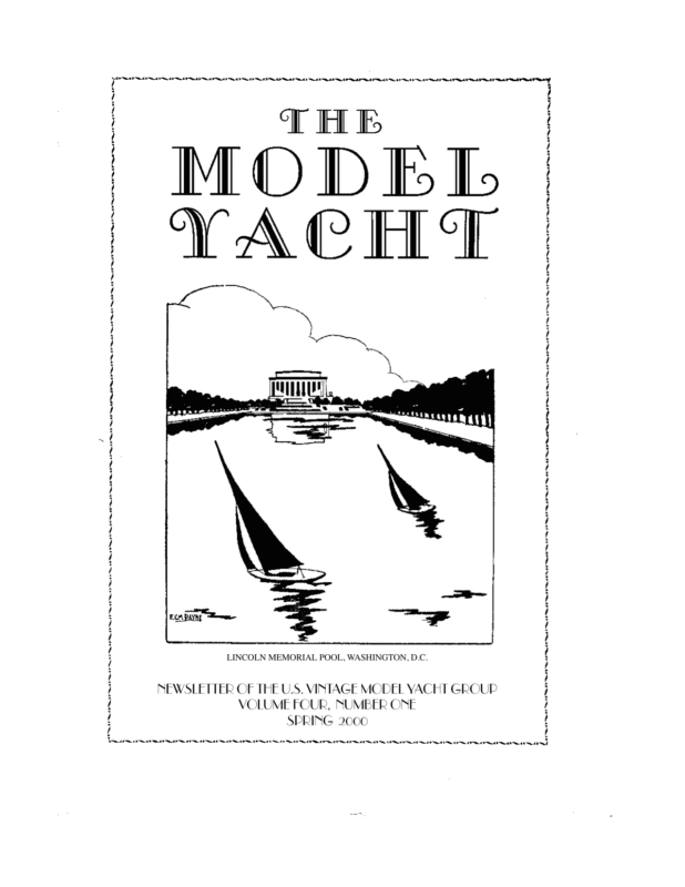
LINCOLN MEMORIAL POOL, WASHINGTON, D.C. NEWSLETTER OF THE U.S. VINTAGE MODEL YACHT GROUP VOLUME FOUR, NUMBER ONE SPRING 2000
NEWSLETTER OF THE U.S. VINTAGE MODEL YACHT GROUP VOLUME FOUR, NUMBER ONE SPRING 2000 Editor’s Welcome We hope you notice the improvements we’ve made in our little journal; we’ve made some minor changes for readability, and improved the reproduction of photographs. We’ve also changed (again) the way we’re managing the mailing list for the newsletter. Please take a moment to fish the envelope out of the trash and look at the number by your name. That number is the volume and number of the last issue we think you’ve paid for. We print 3 issues per volume; this issue is Volume 4, Number 1, so if the number by your name is “41” it’s time to resubscribe. You should also get a resubscribe notice and a self-addressed envelope. If the number is “33” then you’re overdue; we’ve extended all the subscriptions that have ended with the last issue by one, just to make sure we haven’t dropped anybody by mistake. We’ve also had problems with issues lost in the mail, despite the fact that we pay first class postage. So if there is a gap in your set, you think we’ve got you listed wrong, or whatever, just contact us by any of the ways we list in the masthead and we’ll make it right. The technical section for this issue is very special, because it brings to light material that, as far as we know, has lain dormant for a century or more. We hope you enjoy reading about it as much as we enjoyed finding it. Earl Boebert Ebbs and Flows The President’s Message Vintage Membership Our annual $15 fee covers three issues of the VMYG newsletter – “The Model Yacht”, and access to technical assistance and vintage model plans. A VMYG lifetime membership is $100. Our “how to” book/video package on plank-on-frame model construction is available to members but not included with the fee. To subscribe to our newsletter/services or for renewals, send a check (payable to US VMYG) or cash for $15 (or $100) to: John Snow, c/o US VMYG, 78 East Orchard St., Marblehead, MA 01945. For inquiries on our activities, either call me @ 781-631-4203 or visit the VMYG Web Page at http:// www.swcp.com/usvmyg R/C “Vintage M” (VM) Group There are two VM categories: 1945 and prior designs, “Traditional M”, and post-1945 through 1970 designs, “High Flyer M”. For rating rules and VM registration, contact Charlie Roden, VM Coordinator, at 19 Oak Glen Ln., Colts Neck, NJ 07722 and 732-4627483. Email: cer@monmouth.com The focal point of the 2000 National Vintage Regatta at Marblehead, MA August 11-13 is solely VM models. It features R/C and free-sail VM racing plus display judging. Check elsewhere in this issue for the entry form Page 1
Traditional Sailing Craft/Scale Models Group The 2000 racing/display regatta for R/C traditional sailing models is September 23-24 at Spring Lake, NJ. Check elsewhere in this issue for the entry form. It includes scratchbuilt schooner models using design rules, schooners with fin & bulb keels and those built from kits, plus other traditional sailing designs such as skipjacks. Schooner rules can be obtained from our Traditional Sailing Craft/Scale Coordinator Harry Mote at 18 Woodmansee Blvd, Barnegat, NJ 08005 and 609-660-0100. Email: stryker@cybercomm.net Proposed R/C American Classic “50/800” (C50) Group The VMYG supports activities for “M 50/ 800” model yachts from early AMYA designs: 1971 to 1991 M boats having conventional sail rigs and non-kevlar hull material. The C50 Group Coordinator is Dennis Lindsey at 515 N. Lyall Ave, West Covina, CA 91790 and 626-966-9538. Email: lindseyd@flash.net Dennis has a listing of older AMYA M designs and C50 rating rules. “J” Class Challenge Cup Championship Regatta The AMYA and VMYG are hosting the 2000 J Class National Championship (ACCR) at the Mystic Seaport Museum July 28-30. This is an effort to raise visibility for the J Class, given its vintage design origins from America’s Cup (AC) races, and the sport of model yachting. This event is the featured waterfront activity that weekend: practice racing Friday, ACCR Saturday and AC match races Sunday. Reenactments of 1930s classic AC pairings include Enterprise vs. Shamrock V and Ranger vs. Endeavour. It also will have an indoor, three-day model yacht exhibit of vintage and AMYA models at the Seaport. If interested, contact myself to display a model and John Hanks, J Class Secretary, 1849 Rainbow Ave South, Lake Havasu City, AZ 86403 and 520-680-7331, for J racing. Additional information on this regatta and other Mystic Seaport special events in 2000 is available through the Mystic Web Page at http://www.mysticseaport.org Discounted Mystic ticket prices for the regatta and other Museum attractions are available if requested in advance through myself. Multiple-day, model exhibitors and volunteers receive free three-day passes to Mystic Seaport. Vintage Etcetera There are two invitational free-sailed VM regattas within the space of two weeks this summer: the second annual SFMYC VM event (August 5-6) and the sixth annual National Vintage Regatta at Marblehead (August 11-13). Consider attending one of these now-rare events to see how model yachts were once raced before R/C with only the aid of mates and turning poles! The 2000 Marblehead Historical Society (MHS) model exhibit has opened with over thirty sailing models from the 1890s to 1940s. It continues through October 29 with a focus on the past 100 years of model yachting at Redd’s Pond. Notable models include a 1929 large, vane model built/sailed by Capt. Nat Herreshoff, a 1927 “450” Class model designed/built by L. Frances Herreshoff and a 1933 “M 50-800” model designed/built/raced by Roy Clough the originator of the M design in 1930. Finally, volunteers are still needed for the model yacht exhibit at the Mystic J regatta. If you would like to meet with other people on our sport and have free access to the many maritime attractions that the Mystic Seaport Museum offers for a three-day weekend contact me. 2000 Vintage Events WoodenBoat Show – June 23-25 Mystic Seaport Museum, Mystic, CT; VM/Traditional Sailing Craft model displays/demonstrations, plus exhibits of full-size wooden sail/ power boats and accessories/maritime items by trades people. Volunteers and models welcomed. VMYG Contact – John Snow 781-6314203 “J” Class Challenge Cup Regatta – July 28-30 Mystic Seaport Museum, Mystic, CT; J ACCR, 1930s America’s Cup classic J match racing and AMYA/VMYG models display. Volunteers and models welcomed. AMYA Contact – John Hanks 520-680-7331 Press Release: Mystic Web Page. Second VM Free-Sail Invitational Regatta – August 5 & 6 Spreckles Lake, Golden Gate Park, San Francisco, CA; Free-sail racing with vane and Braine gear VM models. SFMYC Contact – Jeff Stobbe 408-475-6233 Page 2
Six-Foot Schooners Sixth National Vintage Regatta – August 11-13 Redd’s Pond, Marblehead, MA; R/C and free-sail (F/S) VM racing and display judging. VM F/S racing – Fri./Sat; R/C racing Sat/Sun. Associated vintage model yacht (30+) exhibit at Marblehead Historical Society to October 29 marking 75th birthday of the Marblehead MYC. Marblehead MYC Contact – John Snow 781-631-4203 Entry Form: This newsletter and VMYG Web Site. WoodenBoat School Model Course – August 14 19 Brooklin, ME; Six-day building course for a wooden model yacht by Thom McLaughlin. VMYG Contact – Thom McLaughlin 813251-6919 International Yacht Restoration School “Family Day” – August 20 IYRS, Newport, RI; VMYG model display; IYRS exhibits/open house, harbor excursions, children’s activities. Volunteers and models welcomed. VMYG Contact – John Snow 781-631-4203 18th Annual Boston Antique & Classic Boat Festival – September 2 & 3 Boston Harbor, MA; VMYG exhibit booth and R/C vintage model sailing. VMYG Contact – John Snow 781-6314203 Traditional Sailing Craft/Scale Model Regatta – September 23 & 24 Spring Lake, NJ; R/C racing and display judging for traditional sailing models such as schooners and skipjacks. Marbleheaders of Spring Lake MYC Contact – Harry Mote 609-660-0100 Entry Form: This newsletter and VMYG Web Site. Spring Lake Open for VM’s Along with the Tra- ditional Sailing Craft regatta, the Marbleheaders of Spring Lake will host a second Spring Lake Open for R/C Traditional Marbleheads on Sunday afternoon, September 24. Contact – Harry Mote. Entry Form: This newsletter. Freesail Model Regatta – October 8 Red Beach, Menemsha Pond, Martha’s Vineyard, MA; Scratch-built, free-sailed wooden models one meter and under. VMYG Contact – John Snow 781-631-4203 John Snow Introduction by Harry Mote There are several people out there, a few of them new VMYG members, who are building large, RC model schooners with a length of approximately six feet on deck. Andrew Charters is one of them. There is either growing interest in boats of this size or our awareness of them is growing — I’m not sure which. Andrew came to our attention via an item and photograph of his “Bluenose II” in the “On the Waterfront” column of the January/February 2000 issue of WoodenBoat magazine. He sent information and a photograph to WoodenBoat because he was looking for sailing company in his neck of the woods in South Carolina. He says that prior to the response from the item and photograph in WoodenBoat magazine, his wife “thought I was a kook and that I was wasting my time.” After the letters of interest from all over the country (none locally) came in, he says, “she started to come around.” He’s now finishing his third schooner. He says, tongue in cheek, “I figure if I build a schooner a year, by the time I’m sixty, I’ll have 20. If I’m lucky, I’ll be able to find skippers to sail them so that I’ll have boats to race against.” Andrew grew up on Grand Manan Island in the Bay of Fundy, was a commercial fisherman for 15 years, has worked in boat yards and now lives in Meggett, S.C., near Charleston. He and a friend won the Doubles Dory Racing Championship as a part of a Grand Manan Island festival for three years in the late 70s. Following is Andrew’s personal narrative that tells why six-foot schooners and how he builds and sails them. Six foot Schooners in Charleston, SC Having been aboard the “Bluenose II” in Saint John, New Brunswick as a boy in 1967, I’ve always had a love for fishing schooners. Down here in South Carolina, I’ve been able to stay in touch with that part of the world and with boat building through WoodenBoat magazine. After reading the books A Day’s Work, by W. N. Bunting, A shipyard in Maine and Howard Chapelle’s American Fishing Schooners, I became hooked on building schooner models. Page 3
Six-Foot Schooner “Bluenose II,” Sailing; I’ve built a coastal schooner, the “Bluenose II” and I’m completing the “Elizabeth Silsbee,” a Starling Burgess design from Chapelle’s book, page 258. I wanted to build large models, yet just be able to get them into the back of my truck. As an example, Bluenose is 6’, 4” on the rail cap, 7’, 9” overall and weighs about 65 lb., with masts and some of the ballast removable for transport. There is a 25-lb. fixed lead keel and eight 3-lb. lead weights that are removable from the bilge, held in with elastics. I install six of them for light air and all eight for heavy air. I use a four-wheeled steerable dolly for launching. Because these boats are larger and heavier than smaller schooners they can take stronger winds and heavier seas. It’s fun to take them out in the harbor and follow along in a full-size boat. I also wanted to build schooners from around the turn of the century. To get started, after reading Chapelle’s The American Fishing Schooners, 1825-1935, I ordered the Ships Plan List Catalog from the Maritime Collection of the Smithsonian Institution for $10 (Ships Plans, NMAN 5010/MRC 628, Smithsonian Institution, Washington DC, 20560). I use only schooner plans that include a full sail plan. This helps in making the sails the right size and the spars the right length, diameter and taper and other details to scale. Next step was to take the plans to Kinko’s, a local copy shop, to enlarge the plans to the size I want, which enlarges everything to scale and saves lofting the model from a table of offsets or measuring from small-scale plans. As an example, I enlarged the “Bluenose” to a 5’ waterline on a 7’ piece of paper. I made an additional copy of the rib section and reduced it 3/8” to allow for 3/16” planking on each side, since the lines are drawn to the outside of the planking. The sail plan, because it is so large, is copied onto several sheets of paper, which I piece and tape together. I saw the ribs out of 1/4” luan plywood and then coat them with West System epoxy so that they don’t split when I screw on the 3/ 16” planking. I chose teak for planking for looks and consistency. I coat virtually all of the wood in the model with epoxy as a moisture barrier. The planking fastenings are #4 x 3/8” self-tapping stainless screws, but I pre-drill for the screws. There are 850 of them in Bluenose. I buy the screws locally for $2.59 per 100. An advantage of a model this size is that the planking and frames are large enough so that there is less a tendency for the planking ends and ribs to split. I also incorporate the deck beams into the rib cut- Page 4
out, which helps simplify and speed construction. Modifications to the original plan include larger scuppers to get rid of water faster in a knock-down. And I install funnel-type ventilators, one forward, one aft, to help handle heat in summer. I buy turnbuckles and some fittings from the Fisher catalog (A.J. Fisher, Inc., 1002 Etowah Ave., Royal Oak, MI 48067, 248-541-0352). I make my own pulleys. For stays, I use plastic-coated leader wire, 120-lb. test, from KMart, with 30-45-lb. crimps. Most hobby stores have brass for rudder stock and chain plates, which I make 1/4” x 1/16”. I’ve been able to buy 1/2” lead from a local salvage yard for ballast. I cut it to size on my table saw. For sails, I had been using a 2.5 oz. Dacron material and recently switched to a lighter 2oz. Dacron. I use a sailmaker to help me lay out the sails. I tape the panels together and then sew them. for them and mount them in the boat a little forward of the main cabin hatch. One controls the mainsail and the other controls the rest of the sails. The mainsail is so large that it needs its own winch. These lift motor winches are controlled by double-poled marine toggle switches, which are operated by RC servos. A third servo operates the rudder. The 12-volt system is powered by an alarm battery, available in any size or shape from a battery store. It fits down the forward hatch. I’m having a lot of fun building and sailing schooners. I hope to eventually build threeand four-masters. But if I do, I’d still want to keep them under eight feet overall. Any bigger seems impractical. I’d be happy to answer questions and even happier to see some six-foot schooners in the Charleston area1. When you build models this large, it takes a lot of power to control the sails. As sail winches, I had been using 12-volt window lift motors from a Mazda 626, but recently went to Toyota lift motors, right and left side, which I think are better. They fit together back to back. I make little hubs and spindles Andrew Charters 1.Andrew can be reached at: 5576 Churchflats Road, Meggett, SC 29449 843-889-8031 — Ed. Starling Burgess’ “Elizabeth Silsbee” Nearing Completion Page 5
An Old Lithograph of canvas allowed each boat, as well as the course to be sailed, being accurately defined. Editor’s Note Of the miniature yachts, schooners of the first class are generally about sixty inches long, are heavily sparred— that is, they have very tall masts, long booms, and bowsprit—and are ballasted with very deep and heavy lead keels. They are either “built” or “cut”—that is, ribbed. and planked, or worked out from a single block of wood. The lithograph on the facing page is from Harpers Young People for June 8, 1880. It represents one of the oldest, if not the oldest picture we have of organized model yachting in the United States. The artist, F.S. Cozzens, clearly was paying attention as all the details of hull form and rig ring true. According to an article by Frank Nichols written in 1894, sailing at Prospect Park began in 1872, so this picture is truly of “early days.” The text that follows is from the same issue. The use of models to explore the characteristics of full-size yachts is of interest, being similar to that described in our technical article this time. The use of elastic sheets to provide a form of self-steering while beating to windward had not come to our attention before. Miniature Yachts On the preceding page is an illustration of a miniature yacht regatta on the Lake in Prospect Park, Brooklyn. In that beautiful Park there are few sights to be seen as beautiful as this. The dainty yachts, perfect in every detail, look like graceful white-winged birds skimming over the water, and the announcement of a regatta on the Lake often attracts more spectators than similar announcements of “grown-up” regattas down the bay. Many of these spectators are very critical, and attend these regattas in order to study fine points of sailing, and to learn what models will show the greatest speed. The little yachts are so carefully planned and built that they often serve as models for those of many tons. Some of the finest yachts of the New York, Brooklyn, Atlantic, and Seawanhaka Yacht Clubs are built from models furnished by winners of races and regattas on the lakes of Central and Prospect Parks. Two regularly organized and officered clubs, the New York and Brooklyn Miniature Yacht Clubs, are the rivals of these lakes, and many exciting match races are sailed between the flyers of the two clubs. These races and all the regattas are governed by the regular rules of yachting, time allowances being made for differences of measurement, and the amount They carry rudders merely to make them look ship-shape, and are steered entirely by their sails. These are so arranged as to balance fore and aft, and the jib and main sheets are made of elastic rubber, so nicely adjusted that if the boat is inclined to sail too close to the wind, the main-sheet stretches, the mainsail is eased off, and she resumes her proper course, with the wind free. If she is inclined to “fall off” too much, and run before the wind, the jib-sheet stretches, the wind spills out of the jib, and the pressure upon her aftersails quickly brings her up on the wind again. The fleet at Prospect Park this season numbers some fifty sail, from sixty-inch schooners down to ten-inch cat-boats, and contains schooners, sloops, cat-boats, catamarans, and one square-rigged steamer. An English cutter will probably be added to the fleet very soon, and interesting races between her and the boats of American model are expected. Unknown Author, 1880 Model Yacht Outreach The education program chairman for the Raritan Yacht Club (full-size boats), Perth Amboy, N.J., bought a copy of Don Kihlstrom’s new book, Sunday Sailors, and was intrigued by its subject. To make a long story short, the Marbleheaders of Spring Lake MYC put together a model yacht presentation and display for a recent RYC Saturday night dinner program. Don Kihlstrom reached into his archives and created a slide presentation on the history of Page 6
model yachting up to the “vintage” years and then gave the presentation to an attentive RYC audience of about 20 people. As part of the display, Don brought with him two antique pond boats and Harry Mote, Pete Peterson, Howard Royce and Marbleheaders commodore Bob Sturges brought five RC model yachts for display and functioned as a panel to answer questions. The RYC sailors were impressed with the workmanship on Pete’s boats and asked many questions about the models and how sailing and racing them compared with full-size boats. Bottom line? It was fun, we met some nice people, we handed out a lot of VMYG and AMYA brochures and we’ve got a promise for a regatta at Spring Lake. We agreed that the Marbleheaders would host a one-day regatta — provide the boats, race committee and trophies for a small group of RYC sailors. The RYC program chairman is to recruit the sailors and call to set a date. Full-size-boat yacht clubs are an obvious “outreach” target — an obvious group from which to recruit model yacht sailors. The experience and language common to sailoring makes communication easy. It’s a nice way to make new friends. Harry Mote Never Trust a Bluepirnt Editor’s Note The article that is excerped below was published under the pseudonym “Reginald Wood Butcher” (probably Charles Farley) in the June, 1946 issue of Model Yachting Monthly. I was prompted to reprint it here by my experiences in building successive “Rip Tide” hulls. In particular, I went back and redrew the sections based on the waterlines plan, and discovered that the drawing (a copy of a master taken off a blueprint of the original) was about 5% off in the lateral direction. The new sections faired much more easily. Silly me, not to have thought of this first. So I figured maybe a reminder was in order. I remarked about this in an email to Russell Potts, who replied: It always helps if the plans are right to start with. As John Gale said to me when he started to build a 19th Century10 Tonner for me. ‘Do you want it like the drawing, or do you want it fair?’ Drawn in pencil, inked over, engraved for reproduction in 1890, printed, photocopied God knows how many times and originally from a bound volume in a museum. It’s not surprising that they get a bit distorted. As would be the plans below, if you simply photo enlarged them to full size. Fairness is the process of developing smooth transitions between the various curves of a hull, in three dimensions. As the great Howard Chapelle wrote, in a section entitled “Art of Faring Lines,” Archie Arrol’s 1937 Midwest M Class Champion, Forever Known as “Detroit News.” Page 8
There is an art to faring lines that is difficult to describe. This is true because the sole judge of fairness is the eye; neither mechanical nor mathematical means will produce a fair set of lines without this assistance. Fairing a hull on the drawing board is tedious and time-consuming, involving working back and forth between diagonals, waterlines, and sections. I suspect many model yacht designers didn’t do it, fairing to the waterlines only, and completing the job on the building board. We have one advantage over the full-sized builders — we can check fairness with our fingers, which are very sensitive in detecting changes in curvature. Occasionally you will see a static model (or one of those reproductions showing up on eBay) whose hull just doesn’t look quite right. Almost always this the sign of a hull that is not fair, often combined with a sheer line that is not “sweet.” Carving small hulls is a good way to acquire “an eye for a ship,” and learn fairness. Closely observing proper hulls, such as those in the Herreshoff Museum’s model room, is also helpful; just remember the adage: Carpenters work to the nearest sixteenth, cabinetmakers work to the nearest sixty-fourth, and boatbuilders work to the nearest boat. And don’t become obsessed with following an untrustworthy drawing! Excerpts A print should be carefully checked before laying out and cutting stock for the backbones, frames, etc. of a planked job, and the waterline or buttock shapes of a glued-up job. Prints from the original drawings are apt to shrink, and in the case of a large print, six feet long or more, this discrepancy may amount to a half-inch. The shrinkage is not constant, that is, sometimes it shrinks lengthwise, other times crosswise. The grain of the paper influences this. On the other hand, a print may stretch when the weather is very damp. Check the distances between stations, and if they vary too much from the stated figure, set these distances off on a heavy sheet of paper or a wide board and cut up the print and adjust it to the proper distance … Bridge the small gaps with a fair line. Blueprints have no consciences. I have checked many and find that some shortened up the distances between stations and at the same time increased vertically, affecting the draft, etc. “Reginald Wood Butcher,” 1946 The Ancient Mariner Speaks Editor’s Note I was looking at the static models at the Smithsonian when I caught a whiff of a familiar smell : seaweed and salt air. Could it be? I glanced quickly at the reflections in the model case but no one was there. At my feet, lashed to an old belaying pin with rotted twine, was the latest contribution from the Ancient Mariner. The Ancient Mariner Speaks Bob Sturges I can’t point my Vintage Marble- head as high as other boats. My speed seems good, but I am being outpointed by the competition. How do I correct this? Ancient Mariner You have a common malady called “point-itis” which may be due to a lack of angle or height. Angle is simply the angle your boat is heading or aiming relative to the wind or to your competition. Try steering your boat closer to the wind. Jib luff telltails can be helpful. If the leeward telltail droops, it is an indication that you can head higher. A masthead fly can also help, particularly in the presence of large windshifts. Many R/C sailors don’t use telltails and flys because they claim they can’t see them. Its true that in distant parts of a course they often can’t be seen, but where they can be seen they are useful. If your boat is also set up with a little weather helm, it will continually try to reach maximum angle and will even require a kick of the rudder occasionally to prevent luffing of the sails. Steering to windward requires con- Page 9
stant adjustment and you should always be ready to angle higher in puffs and in stretches of flat water, in order to grab that extra half boat length when no one is looking. The second aspect of pointing is height. Height refers to the actual distance made good to windward or a measure of how the boat is actually tracking. Wind side forces on the sails cause leeway or side slippage and its not your heading, but where you end up that counts. Before you try for improved height, you must first be going full speed in order to maximize the efficiency of your underwater foils. You will often see boats that don’t appear to be pointing too high, but watch out when they get underneath you. They are living proof that speed produces height. Once you are going fast, the key control for increasing height is adjustment of jib and mainsail leeches. The sail sheeting angles should be about 15 degrees for the jib and 5 degrees for the main. In moderate air and flat water the jib sheeting angle can be brought in to about 12 degrees. Next reduce mainsail twist in order to pull the top of the leech more to windward. This may require both a vang and/or mainsheet adjustment depending on your particular rig. Be careful not to overdo it, the top leech batten should be no more than parallel to the boom or slightly to weather. This will start pushing your stern to leeward and load up your helm a bit, but if it only hurts your helm and Possible Ancient Mariner Sighting, ca. 1895 doesn’t help your height, try closing off the upper jib leech for more bite. Placing minimum tension on the jib cloth downhaul, helps height by giving the jib a narrower leading edge or luff. In terms of pointing, however the leech adjustment is more important than any luff adjustment. If the backstay is over tensioned in light air, it will flatten and de-power the jib and hurt height. There are also other factors that contribute to height loss. These are excessive heel, sails too full in flat water, sails too flat in choppy water, and sail sheeted too hard for the conditions. In most cases pointing higher boils down to first achieving full speed and then shifting into point mode by trimming your main to tighten your leech a bit. Finally don’t hesitate to ask that sailor who is continually pinching you off to leeward for a little help in solving your pointing problem. Charles Roden It is well known that vintage boats with a full skeg are slow and difficult to tack. How does one make the best of this situation? Ancient Mariner The old adage, “look before you leap” applies to tacking. There is no free lunch in tacking as several boat lengths are typically lost when a keel boat tacks. In moderate air the loss is typically about two boat lengths and the loss increases to about four boat lengths in light air . If you are unfortunate enough to get caught in irons, then the race is over for all practical purposes. Minimize tacking as much as possible, particularly in light air. It is always necessary to tack, of course, when you are running out of water (shore) or wind (flat spot). It may also be necessary to tack to clear your air from a competitor or to respond to wind shifts. Always ask yourself if a tack is necessary before you leap to throw that steering lever over. Having decided that a tack is necessary, it is important that the boat be in a good position to tack. Make sure that the boat is close hauled before tacking in order to minimize the angle through which the boat must be turned. If the boat is set up with a little weather helm, this will happen naturally. A mast head fly is also helpful to indicate if the boat is sailing below close hauled. Next boat speed is needed in order to tack as the rudder turning force is proportional to the square of boat speed. Don’t tack in holes. Page 10
The best of all worlds is to wait for a wind puff when the boat is heeling before tacking. In addition to achieving adequate speed for rudder control, heeling produces a sail force couple that attempts to turn the boat into the wind and helps the tacking process. Now let’s consider how best to turn the rudder during the tacking maneuver. Turning the rudder also puts on the brakes. Apply a small amount of rudder at first to get the boat turning without slowing it down significantly. Increase the amount of rudder as the boat slows naturally and comes head to wind. Maximum rudder should be applied as the boat comes head to wind and is coasting. As the boat turns to the new tack gradually reduce the helm until it is back to centerline. What constitutes maximum rudder is important. If a rudder is turned beyond a critical point, the water flow on the suction side of the rudder that contributes to the foil lift force will separate and the rudder will stall with a large reduction in turning force. This critical angle is typically 15 degrees for a high aspect spade rudder. A low aspect skeg rudder has a greater critical angle that is between 25 and 30 degrees. Be sure to set up your rudder linkage so that you cannot exceed a rudder angle of over 30 degrees. This will prevent stalling the rudder in the heat of battle. In flat water and a moderate breeze you can often get by with less rudder and the boat can be turned more gradually and use its momentum to coast directly upwind for a nice gain. In windy or lumpy water conditions, the flogging of the sails or added water resistance will slow the boat quickly, and a faster tack with full rudder will be necessary. In very heavy air these factors may prevent you from tacking in gusts and it may be necessary to look for a momentary lull before tacking. My last word of advice is to get out to the lake and practice tacking in all conditions. No one said it would be easy, but it is a lot more doable than you might at first imagine. Its all part of the challenge of vintage sailing. The Ancient Mariner Bits of Oakum Model Yachting Bibliography Russell Potts informs us that there are now two U.S. sources for A Bibliography of Model Yachting: Edward Lefkowicz 50, Angell St., Providence RI 02906. 800 201-7901; Fax 401 277-1495 Email: seabooks@saltbooks.com Laurence Howland Howland & Co, 100 Rockwood St, Jamaica Plain, MA 02130. 617 522-5261; fax 617 983-3448. The bibliography is a “must own” reference work for anyone interested in our field. Full Size Plans Full sized plans for the lovely Bassford yacht described overleaf will be available in late June, thanks to the efforts of Thom McLaughlin. One sheet, shipped rolled in a tube (overseas folded), $30.00 postpaid. Overseas orders, please add $5.00 postage and pay in U.S. funds. Orders to the editorial address. The Model Yacht is published three times a year by the U.S. Vintage Model Yacht Group. Copyright 1998,1999, 2000, U.S.V.M.Y.G. Reproduction for noncommercial purposes permitted; all other rights reserved. Editorial Address: 9219 Flushing Meadows NE Albuquerque NM 87111 Email: boebert@swcp.com Phone: 505 823 1046 Officers of the U.S. Vintage Model Yacht Group: President: John Snow Eastern Vice-President: Ben Martin Midwest Vice-President: Al Suydam Western Vice-President: Dominic Meo, III Southeastern Vice-President: Thom Mclaughlin Traditional/Scale Coordinator: Harry Mote Vintage M Class Coordinator: Charles Roden Classic “50” Coordinator: Dennis Lindsey Historian: Earl Boebert Historian: Charles Williamson Archivist: Jim Dolan Page 11
The yacht “Katrina,” mentioned by Bassford as an example of the use of model yachts to aid full-scale design. Note the similarity to his boat. The Model Sailing Yachts of Franklyn Bassford Editor’s Note We have discovered material which sheds light on some of the model yachting practices of the 1890’s, and also provides us with the plans for an uncommonly graceful boat. In particular, the newly discovered material gives us previously unavailable details about the rigging and fittings of model yachts of this period. son River, and Long Island Sound. The manner of racing was distinctively American: races were held on triangular courses of as much as a mile. Skippers followed their boats in one-man skiffs and trimmed or altered course as necessary. Despite the fleet racing appearance, each boat was actually being timed, with an adjustment made for its sail area and 10 seconds deducted for each time its skipper was obliged to touch his boat. The racing classes were based on LWL measurement only, with a handicapping system to compensate for differences in sail area. Model Yachting in the 1890’s Organized model yachting began, as best we can tell, in the New York area in 1872. It grew rapidly in popularity and by the 1890’s there were three clubs, an inter-club union to determine championships, and spirited competion. The boats of the period were, of course, freesailing, and were raced on open water: the lake at Prospect Park in Brooklyn, the Hud- Franklyn Bassford Lewis Franklyn Bassford (1856-1897) was the son of a composer, who had written an opera called The Phantom Ship, based on the story of The Flying Dutchman. When he was three months old, his parents set sail for France, where his father was to enroll in the Paris Conservetoire. They were lost at sea, and he was raised in New Jersey by his maternal grandparents. He became an expert on yachting and a marine artist; at least one of his Page 12
Bassford’s 1894 design, top and left, and his 1895 design, bottom and right. Note the modifications to increase stability: deeper draft, increased beam, and harder bilges. The profile plan of the later boat is seriously distorted; when redrawn properly, she is even better looking. Full sized plans of the 1895 hull will be available from the Vintage Group in June 2000, thanks to Thom McLaughlin. Page 13
works is reported to be the basis of a Currier and Ives print. He wrote four articles for Outing magazine, which appeared in February and March 1895 and March and April 1896, describing a first and second design which I will call the 1894 and the 1895 boats. These articles give us a remarkably detailed view into at least one designer and builder’s practices of the day. As we will see, the model yachting done by Franklyn was in support of his full-scale yacht designing, and so it is not clear how widely spread some of his ideas were. Sadly, his yacht making venture failed, and he committed suicide in 1897. Design Principles Objectives These were summed up best by Bassford himself in the opening paragraphs of his first article, aptly titled “Miniature Yacht Modeling. Its Practical and Scientific Service:” Model yacht sailing, of the scientific and practical sort, must not be confounded with the pastime of sailing shop-made toys, the diversion and delight of many youths with an inborn and inherent passion for the sea. Nor must it be confounded with the methods of those who themselves build models, sometimes monstrosities, for the mere amusement of winning races in model yacht club regattas, regardless of whether or no their craft could be reproduced in any other proportions. The model yacht building and sailing of which I desire to treat is of great practical and economical value, for by it some of the most abstruse and puzzling questions of “form,” in its ability to ride over and cut through a seaway, to get to windward, and other like points, can be more decisively demonstrated than by actual vessels. Strange as this may seem at first blush, a moment’s consideration will show its reasonableness, for the miniature model when sailing is sailing entirely on her form; the simplicity of her equipment and entire absence of the individual element necessitate this result. If she fails in any particular it is the failure of her design; if she succeeds the success is attributable to her design alone; whereas in the actual boat the man at the wheel is able to counteract faults and tendencies to deviate from the true course and to hide many defects. If the model shows creditably it is on its own merits, whereas in the larger vessels it may be, and often is, the captain and the crew to a great extent to whom the credit belongs. Owing to the capacity of many yacht captains, good results are often obtained from poor boats, and “the navigator’s skill must increase with the size of the ship; “but in the model, aside from the initial trimming of the sails before the start, the boat herself must do the rest, and it is about certain that the worst one will get worsted. Both these results have been too often noted to require further argument. An actual yacht may not be properly masted, the center of effort of her sails may be very far from her center of lateral resistance, and the profile form of her keel may be more of a hindrance than a help; yet, with an extraordinarily competent captain, she may still very often win, which a model yacht so defective never could. When, then, the mode} does win, a form which is worthy of imitation has been found and at a very slight expense. The crucial test of the value of the model in solving these problems was made in the fall of 1889 by A. Cary Smith, the well-known yacht designer. He had built the seventy-foot sloop Katrina, and she carried a lee helm, which, it was thought, might be remedied by moving the mast aft, the step of which, however, was so close to the centerboard trunk that the latter would also have to be moved, and the experiment promised to be very costly, with no certainty of entire success. At Mr. Smith’s suggestion an absolute facsimile of the large boat was built on a scale of an inch to the foot, and it also carried a lee helm: “the baby had the tricks of its mother,” as was well said at the time. The fault was first inexpensively corrected in the miniature, and the same alterations then applied to the large vessel on precisely the same relative proportions, showing again the same results, the Katrina winning the New York Yacht Club’s regattas of 1890-’91 over the Shamrock (which had defeated her in ‘89) While this test is absolutely final and conclusive, it only bears out results which are obtained and noted every day in the handling and performances of all really good miniatures. Hull Bassford then continues to argue that a model should have the proportions of a “proper” full sized yacht, that is, one that is esthetically pleasing and most importantly, one that could have been built. This philosophy parallels that of “free-lance” models in model railroading, which are replicas of nonexistent, but perfectly plausible, prototypes. Bassford chose an LWL of 35”, the smallest allowed by the rules of the time and Page 14
shape (in profile at least) of a centerboard, and two kinds of fin keel. The shape and method of attachment of each is shown in his sketches. His preference was for the full fin keel, which slips into a slot in the deadwood and is held on the aft end by a tab, possibly riding on a transverse screw, and the fore end by the threaded sleeve shown. The other form of fin keel is attached by “turn buttons,” which go in the slots shown and then are rotated 90 degrees to lock the fin in place. Bassford gives the displacement of the 1895 boat as 14.9 lbs and claims that 10 lbs. of lead can be carried; I calculate the displacement at closer to 16 lbs, and based on plank on frame M boat experience the hull should swing 11 to 11 1/2 lbs of lead easily. Construction Three methods are described: bread and butter using solid lifts, bread and butter using lifts with the centers cut out, as we know today, and plank on steamed frame. Interestingly, Bassford spends considerable time extolling the advantages of cutting the centers out of lifts; checking other publications of the era shows that this was, indeed, an innovation at that time. one which conveniently scales to the full sized “70 footer” class at 1/2” to the foot. This yields a boat a little over 50” LOA, which has proven to be a very convenient size. He then gives the following proportions: LOA = 1.5 LWL. Maximum draft = 6 to 8”, with the point of maximum draft a little ahead of the sternpost, yielding a rounded keel which sheds weeds, is easier to unstick if aground, and provides a “reverse truss” for strength. Rig Principles Bassford’s rig is closer Maximum beam at 60% LWL, which yields the “raking midsection” type of hull. Freeboard of 1/10 the LOA at maximum point, down to 1/20 at the rudder post, rising again to avoid the appearance of a droop. Bulwarks and rail: 5/8” at point of maximum freeboard, tapering to 3/8 at the point of least and then down to nothing at the taffrail, to facilitate draining of the deck. On his second hull he added 2” scuppers with 1 1/2” between each, starting at the attachment point of the aft shroud. Stability Bassford argues strongly for removable external ballast in order to carry the substantial amount of sail popular at the time, and gives three designs: “lead centerboards,” in which the external keel simulates the to full-size practice than was common amongst the designs of those who engage in the “mere amusement of winning races in model yacht club regattas.” He duplicates in essential detail the “triple headed” cutter rig of the day, with its three foresails (jib, staysail, and jib topsail or flying jib), the gaff-rigged main, and club topsail. Most of his contemporaries, who were less concerned with relating to fullsize boats, were running simplified gaff rigs Page 15
Sailplan of the 1895 boat. Lines indicate direction of selvage of sailcloth. A thin brass wire batten is sewn where the two pieces of the jib topsail are joined, to flatten it under pressure of the wind. 19 32 36 29 19 (1/2) 23 19 48 43 23 29 33 20 24 (1/2) 14 40 (3/4) (3/8-1/2)) Dimensions of the sails, in inches (not to scale). The degree of roach (curvature) of a particular edge is shown, where applicable, in parentheses. Page 16
with no topsail and one or two foresails. shrouds, then tapered above that. As the sail plan shows, the result is indeed a pleasing rig. With all sails set, she carries an impressive 1830 square inches of sailcloth. This full rig would only be used in light air. When it starts to blow, sail is shortened by removing the club topsail, the top mast and its side and fore stays, the spreader, and the jib topsail. This not only reduces the sail area to a more reasonable 1400 square inches, but it also drops the center of effort seven inches (the CE moves about an inch aft in the process). To give a comparison with contemporary designs, an EC 12 has similar draft, about 2/3 the sail area, and carries almost twice as much lead. Hence the need for external ballast. The artist in him comes out when he discusses sail proportions: If a model yachtsman has the real interests of his craft at heart he will devote all his energies to producing a light and shapely vessel, and cutting her spars and sails of stylish and Standing and Running Rigging The standing and running rigging is shown on the diagrams on this page; the rigging of the halliards will be shown in the drawings of the fittings. effective shapes as well as proportions. For instance, nothing can so materially add to appearances, at any visible distance, as a cleanly cut club-topsail, with extremely short leach set over a gaff, peaked as high as possible to preserve the necessary area in the mainsail, or a jib with a high clew and a staysail carried well up the masthead to close the otherwise awkward-looking gap between the forestay and the jib-leach. The proportions he gives are as follows: Mast at 1/3 LWL. Height of mainmast = LWL. Mainboom 1.25 LWL. 70% of mainboom to jib tack. 60% of mainboom for gaff. Hoist of mainsail equal to or slightly less than length of gaff. Topmast = gaff plus 2-4” for setting club topsail. 55% of the fore space devoted to the jib boom, 45% to the staysail boom. Jib topsail 50% of the stay carrying it. Spars thickest in center and tapering to both ends, except for the mainmast, which is parallel to the point of attachment of the As mentioned before, the standing rigging is variable depending on the sail set. The permanent rigging consists of the three side stays on either side which run to the base of the spreader, and the two fore stays that support the jib and the staysail. The other two side stays, and the topmost fore stay, are removed when sail is shortened. I have concluded that the removable spreader is also taken down with the topmast, as there is no purpose for it after the side stays are removed, and Page 17
Bassford emphasizes the importance of reducing windage by removing the topmast as well as the topsail clubs. The running rigging shows considerable ingenuity. The basic mechanism for adjusting the sheets is the pin rack. There are two; one on the spreader and one on the deck just after the mast. The deck rack is twelve inches long by 3/4” wide and is placed about six inches aft of the mast. Two or three lines of holes, spaced 1/2” are drilled in the board. Screw eyes with their threads cut off are used for the pins. The sheets for the foresails run as shown in the diagram. One end is made fast to an eye on the port side of the boat. The sheet is then reeved through a hook attached to loop on the boom, through an eye on the starboard side, and then back to a pin on the rack. The sheet for the jib topsail is made fast to a pin arm of the spreader/pin rack, reeved through a attached to loop or grommet in the clew of the sail, and then made fast to a pin on the other arm. Based on the sketches, I’ve concluded that the spreader exceeds the beam by about an inch on each side, which would make it 12” long. The mainsheet is more complex. The diagram shows the sheet in its close-hauled, or beating position. It is hooked to an eye in the stern, then reeved through an open eye on the boom, down to the tiller, back to another open eye, along the boom to a closed eye, and then to the deck and forward to the pin rack. When running or on a reach, the line is cast off from the stern eye and the two open eyes on the boom, and hooked to the tiller. Thus the “Z” reeving of the line when close hauled takes up the considerable difference in sheet length between close hauled and boom outboard with such a long mainboom. The advantage of this scheme is that it eliminates the need for separate beating and running sheets. The self-steering mechanism is the sheet-totiller rig that was standard at the time. The center of effort of the mainsail is a good eighteen inches or so aft of the boom; when swung out for a run, this exerts a powerful asymmetric force, tending to turn the boat in the direction away from the boom. To compensate, an aft-facing tiller is rigged with a tensioning elastic on the forward end. The mainsheet is hooked to the tiller. As the boom swings further outward (indicating greater wind force), the sheet pulls on the tiller against the resistance of the elastic and applies compensating rudder. The range of rudder angle is controlled by a traveller with two threaded buttons; this is placed at right angles to the rudder and the buttons A single “jumper stay” is rigged on the port side. This runs from the end of the gaff, through a loop on a short line, and then down to the mast partner described below. This line is used to pull down the end of the gaff and hold the club topsail taut while running. It is loosened for runs and reaches. The halliards are shown in the fittings diagram, although in some cases you have to look a little carefully to see them. Bassford, interestingly, recommends the “jam bowline” knot even though flat toggles or bowsers were well known at the time. There are two halliards for the mainsail. The “peak halliard” is reeved through the three rings on the upper mainmast in the zigzag fashion shown. At the apex of each “V” is a ring that attaches the halliard to a fixed line, or “pennant” on the gaff. This arrangement sits on the port side of the club topsail, when it is set, and raises the aft end of the gaff. The peak halliard is tensioned on itself by a loop and jam bowline on the top ring. The “throat halliard” is a short line that runs from the bottom of the three rings to jaw of the gaff and is looped and tensioned on itself; it is used to raise the jaw end of the gaff. The deck plan given in the first article. This is evidently from a preliminary study, because it is inconsistent with other plans and statements in the text. The beam is too narrow, and the two eyes for the staysail sheet are aft of the mast instead of slightly forward of it. Note that this diagram shows an earlier version of the running rig, where the sheets run from peg rail to peg rail. Page 18
Page 19
Close Hauled, Mainsheet Looped Through Open Hooks This Distance Should be 12” Set for Run or Reach; End of Mainsheet Unhooked from Deck and Moved to Middle Eye Page 20
A single halliard runs from the bottom corner of the club topsail, down the mainmast, and is made fast to a mast partner. The jib and staysail halliards are attached to the top corners of the sails, and run through the bent wire bridles then down to the mast partners. Fittings and Construction The details of the fittings are shown in the previous two pages. Most of the drawings are self-explanatory, but a few notes are in order. All fittings made from sheet are 1/64” brass. The spreader is made of hickory or equivalent hard wood, riveted to the brass half-collar. Bassford did not give exact dimensions for all the spars, but I am fairly confident from the text and drawings of the following sizes: The mainmast is 5/8” diameter, tapered as described before. The topmast is 3/8” diameter, straight to the band holding the stays and then tapered and with a finial as shown in the drawing. All other spars and booms are 3/8” in the center and taper to 1/4” at each end. The clubs for the topsail are a constant 1/4”. The hoist of the mainsail is attached to the mainmast with brass hoops spaced at 1 1/2” intervals. side band is fixed to the club. Each club is cut with a shoulder so it can slip into the bands only to the proper length. When the topsail halliard is made fast the tension on the sail holds the clubs in place. Likewise, the topmast slips into a lower band which is fixed to the mainmast, and holds an upper band which slips over the top of the mainmast in the position shown. It is also shouldered for proper fixing. Since the topmast is removed whenever the club topsail is, it would be reasonable to fix vertical club permanently to the topmast. The bowsprit is fixed much like the clubs and topmast. It is shouldered, and slips through a gammon strap on the bow and into an inboard strap attached to the deck. Both straps are rolled from sheet brass. The inboard strap is cut with a tab that is rolled back and soldered to form the point of attachment of the staysail stay. An inboard bobstay plate is fixed to the bow with the loop at the waterline. The bobstay runs from it, through a turnbuckle, and to the bowsprit strap as shown. Bassford recommends 1/16” brass rod for the bobstay. The sketch, but not the plans, shows two side stays attached to the bowsprit strap. These would run back to hooks at deck level, two or three inches aft of the bow. a 1/8” square piece of “cigar box wood” (socalled “Spanish Cedar”) which runs the length of the gaff on its lower side, giving the cross section shown above. Holes are drilled laterally through it every 1/2” or so and the mainsail is laced through these. The main, jib, and staysail booms are equipped with wire staples every 1/2” to hold a jackline to which the sail is laced. The ends of the sails are sewn to the eyes on the brass bands at the end of the spars. The standard practice of the period was to put a tube in the deck and run the mast down to a seat in the keel. Bassford rightly criticizes such an arrangement as being prone to leaks. Instead, he runs an interior brace up to the deck at the mast position, and places this mast step above it. It is made from 5/8” I.D. brass tubing, cut and bent as shown. The four ears at the base are riveted and soldered to an octagonal brass plate. The tabs are bent down to form the four partners, to which are attached the halliards for the club topsail, jib, and staysail and the jumper stay. Note the slot for the gooseneck. The “inverted L” gooseneck fitting is fixed to the mast, with an eye on the mainboom. The mast fitting slides into that slot on the mast step, locking the mast properly in place. The club topsail is laced to two clubs with a running lock-stitch, which leaves each turn circular rather than a spiral. The clubs attach to the gaff and topmast with two double-loop bands each. The inside band is fixed to the topmast and gaff, respectively, and the out- Sails were made from a cotton textile called “Lonsdale Cambric,” now extinct. This is a very tightly woven (150 or more threads to the inch) cloth made from long staple (Egyptian or Sea Island) cotton. No truly satisfac- The gaff is equipped with a “bridge.” This is Page 21 Sails
tory replacement has been found, although the “down cambric” used in down pillows and comforters is close; it is tightly woven to prevent the ends of the feathers from poking through. The jib and staysail and are sewn to their respective stays as shown in the bowsprit sketch, with widely spaced loops on the luff (forward edge) and spiral sewing around the jackline on the boom. We can safely surmise the jib topsail was sewn to its stay in a similar way, although of course it does not have a boom. Bassford specifically states that there is no halliard for the jib topsail. Some Thoughts on an R/C Replica It’s hard for me, anyway, to look at the elegant form of this boat and not have a itch to see that sail plan rising like a cloud formation from my favorite lake. So I plan on building one, just for “windling” as my friend Mark Steele of Aukland would say. There are two problems to be solved: the provision of external ballast in an esthetically pleasing way, and the running rigging, especially the control of the jib topsail and the jumper stay. With regard to the external ballast, I personally prefer the “lead centerboard” approach as the best looking. Assuming a displacement of 16 lbs, one would like to plan for an initial ballast of about 12, cutting it down as needed to trim the hull. The sketch below shows one which “back of the envelope” calculations show that, if made 3/4” thick and to a roughly streamline cross section, should provide the required weight without doing violence to the design center of buoyancy or the center of lateral resistance. The rig is going to require some ingenuity. A heavy duty sail winch like the RMG is clearly called for, as, for that matter, is a pretty hefty rudder servo. The pin rack provides a nice way to hide the fairleads going below, and the jib topsail sheet can be run across the spreader and down the mast; beyond this I have not gone. Suggestions will be more than welcome. I intend to make my model a replica of Bassford’s, and not a model of some notional full-scale yacht, in keeping with his clearly stated philosophy: Impractical model yacht sailors simply yearn for all the minutiae of modern racers of the largest sizes, and fancy they add materially to appearances by bedecking the models with boats in davitts, sky-lights, hatches, anchors and chains, etc. etc. which, as a matter of fact, cannot be seen at all when the model is a hundred or two yards distant. Each unnecessary fixture handicaps her from the possible speed which should alone be sought. Acknowledgments I would like to thank my wife, Judy, for discovering the original articles, Thom McLaughlin for producing the full-sized hull plans, and the following members of the Bassford family for responding to my queries: Ethan F. Bassford, F. Ginter, Dawn Hanlon, David Lambert, Jack Neff, Sylvia Sawyer Sebelist, Kevin Spaulding, and Marjorie Bassford Spille. Earl Boebert Profile, showing a possible design for a “lead centerboard” form of external ballast. Page 22


