The Model Yacht is a published three times a year by the US Vintage Model Yacht Group
- 2004 National Regatta Report. by John Atwood
- Satanita. by Earl Boebert (1893) – largest and fastest cutter ever built
- Donald Duck. by Earl Boebert – Henry Tucker M class design plan
- An Inexpensive Bench Block. by Dave Querin
- Thermopylae: A Sailing Model Clipper Ship. by Graham Henley (1950) – plans and instructions

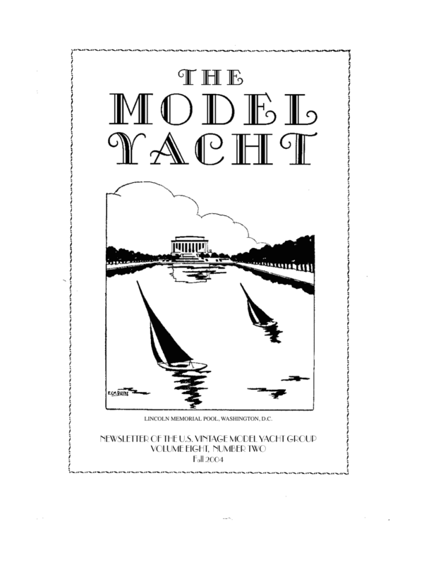
LINCOLN MEMORIAL POOL, WASHINGTON, D.C. NEWSLETTER OF THE U.S. VINTAGE MODEL YACHT GROUP VOLUME EIGHT, NUMBER TWO Fall 2004
NEWSLETTER OF THE U.S. VINTAGE MODEL YACHT GROUP VOLUME EIGHT, NUMBER TWO Fall 2004 Editor’s Welcome In this issue we present our first ever article on a square-rigger: the classic Thermopylae. After all, our charter is to support modelling of traditional watercraft, and what could be more traditional than a clipper ship? In addition we have plans for a neat little 36R from 1953 and lines of the great cutter Satanita, a candidate for a large-scale model. We’re starting to catch up with the calendar, and should have our next issue out on schedule at the end of the year. This has been a very busy and rewarding year for us. Also, your humble editor retires from his day job for good in mid-February, and so we should be able to do a little better with regard to keeping on schedule. A reminder that we track our subscriptions by Volume and Issue number, and put the number of the last issue we think you’re signed up for next to your name on the mailing label. This is Volume 8, Number 2, so if there’s an “82” next to your name it’s time to renew and there should be a renewal slip and a self-addressed envelope in with your issue. Finally, I would like to thank Charlie Roden for all the effort he put into being our Vintage Marblehead coordinator since the beginning of our group. The baton has been passed to John Henson, also a member of the Marbleheaders of Spring Lake, a club which has been unstinting in their support of our activities. Earl Boebert Ebbs and Flows The President’s Message Vintage Membership VMYG annual membership is $20 for three issues of our newsletter – The Model Yacht. US VMYG lifetime membership is $100. Members then have access to technical assistance and vintage model plans. Plans will eventually include those electronically scanned, plus those to be made available in future through American Model Yachting Collection (Houk Archives) by Mystic Seaport Museum Library. VMYG “how to” book and video package on plank-on-frame construction is available separately. To subscribe to or renew our newsletter and services, please send $20 check (payable to US VMYG) or cash ($100 for life membership) to: John Snow, c/o US VMYG, 78 East Orchard Street, Marblehead, MA 01945. For detailed information, you can call me direct in Marblehead at 781 631 4203 or visit VMYG Web Page at www.swcp.com/usvmyg 2004 VMYG National Regatta Our 10th annual VMYG National Regatta was held Sep. 16-19 at Mariners’ Museum in Newport News, VA. It was unqualified success thanks to John Atwood and Museum support. Activities included R/C VM, V36 and Traditional Sailing Craft models racing, plus AMYA Region 3 J Class Championship. John developed and coordinated this event in close collaboration with the Museum staff, with the Museum now wanting to host another model yachting event in 2005. John is working to establish R/C model yacht club Page 1
as well, which would use Museum’s 165-acre Lake Maury as its home sailing site. Check elsewhere in this newsletter for report on our 2004 national regatta by John Atwood. 2004 Museum of Yachting Activities VMYG involvement with AMYA and the Museum of Yachting at Newport, RI on several 2004 MY events is ending on Oct. 31st. The key attraction has been unique model yachting historical exhibit of 65 models: The World of Model Yachts. Colored catalog of exhibit is available from VMYG. Check VMYG Web site for details on ordering catalog. Vintage Etcetera Yankee III J Model Book Check VMYG Web site for details on Earl Boebert’s new “how to” model building book on 1930 36-inch, Yankee J Boat design as entry-level R/C vintage model. Vintage 36-Inch (V36) Model Group VMYG will continue to monitor interest in V36 designs, as there were just three of these boats at our national event at Mariner’s Museum. Mid-West Representative VMYG still needs volun- teer as our Mid-West representative. If you are interested, contact Earl Boebert or myself. Notes of Appreciation: Charlie Roden VMYG would like to recognize extraordinary efforts of Charlie Roden, as VM Coordinator from early 1995 to October 2004. Charlie is now retiring from this position after developing our fleet of VM models to over 75 boats. Thus, he has been instrumental in overall success and promotion of VMYG during past decade of our existence as well. John Henson, Commodore of the Marbleheaders of Spring Lake, has agreed to take over the duties of the VM Coordinator. John’s contact information is: John R. Henson, 1212 Sandra Place, Brick, NJ 08724. Telephone 732 458 1370, fax 732 458 0333, and by email: during the Museum of Yachting 2004 season. Key volunteers were Dave Brawner, Jim Dolan, Norma Greenhalgh, Ron Rhault and Ken Shaw. There were eight J and eight EC12M skippers that participated. The J Class regatta awards ceremony was conducted in the Museum, with actual stern-plate of 1934 “Rainbow” J Boat as backdrop. Also, the sailing site was so situated that restored 1934 Endeavour J Boat could be viewed sailing into Newport Harbor when R/C J Class models were racing. Potential 2005 VMYG Activities: April 2005 Woods Hole Model Boat Show, Cape Cod, MA senlivjh@aol.com 2004 Museum of Yachting Model Yacht Regatta A few issues ago we ran the plans for Water Baby, a 25” LOA free-sailing boat. Here is Graham Reeves’ version next to an International One Meter. We now have full size plans for the plank on frame version of Water Baby, $20.00 postpaid. It makes an excellent first project. VMYG appreciated efforts of AMYA volunteers who helped to run AMYA J and East Coast 12 Meter championships at Museum of Yachting on Newport Harbor Oct. 8-10. This event was one of several performed in conjunction with World of Model Yachts exhibit Summer 2005 VM National Regatta, Mariners’ Museum, Newport News, VA September 2005 Traditional Sailing Craft Regatta, Calvert Maritime Museum, Solomons, MD Page 2 John Snow
The 2004 Annual Regatta The 2004 Vintage Regatta at the Mariners’ Museum September 16th through the 19th, 2004, was an overwhelming success. First and foremost, the event would not have been such a success without the Mariners’ Museum’s dedicated staff who worked tirelessly while dealing with uncooperative weather. The Museum’s staff performed exceptionally in every respect, and we all certainly appreciate a job well done. A vast amount of behind the scenes work went into hosting this regatta utilizing many museum personnel who were directly involved in coordinating, planning and working on-site and behind the scenes on this event. As an example of the work involved, there was twenty-four hour on-site security, maintenance personnel to help with all the details entailed in setting-up and mon- itoring unforeseen problems, and providing breakfast and lunch for all competitors. The Museum staff provided an informational package to each participant which included brochures about their beautiful Museum and the surrounding area’s points of interest. The information packets also included a pair of 2004 Vintage Regatta brass plaques for each participant. They also generously provided the gorgeous trophies along with T-shirts, and a Museum coffee cup. All participants who were asked said they had never been treated as well and as graciously as they were at this Regatta. We all want to convey a sincere and heartfelt thank you to the Mariners’ Museum! Lake Maury gave us lasting memories of friendship and camaraderie that will last a lifetime. John Atwood A look at the terrific facilities provided by the Mariners’ Museum. Turnout was great, unfortunately it included one unwelcome guest: the remains of Hurricane Ivan. Friday was tolerable, Saturday was gusts and squalls, and Sunday it just blew and blew and blew … Results of the 2004 National Regatta Event First Place Second Place Third Place Fourth Place J Class David Brawner Hal Slentz-Whalen Rick West Bob Kjellberg Vintage M Alan Suydam Harry Mote Joseph Cieri Tom Younger Skipjacks Buck McClellan Tom Younger George Surgent Harry Mote 50” Schooners Joseph Cieri John Atwood Alan Suydam Martin Hayes Big Schooners Andrew Charters Richard Lamsfuss George Surgent Buck McClellan Page 3
The mighty Satanita, thundering along with every stitch set. If you look closely you can see that this huge cutter was steered with a tiller instead of a wheel; taking the helm was not for the faint of heart, or weak of grip, for that matter. The main boom was 88 feet long. Satanita Satanita was the largest, and fastest, cutter rigged yacht ever built. She was designed by the prolific British designer J.M. Soper and finished in early 1893. She was clocked on a timed run at 16 knots. In 1894 she lived up to her somewhat sinister name by ramming and sinking Valkyrie II. The resulting liability litigation (yes, they had lawyers and insurance companies back then) established the precedent that yachts in a race were governed by the racing rules and not the much more conservative commercial collision regulations. The table shows her size relative to the J Class Weetamoe: longer, broader, lighter and packing more sail. A 1/16 model, while not legal under the AMYA J Class rules, would provide an interesting contrast to the J’s. It would be eight and a half feet long, and make quite an impressive sight on the water. Page 4 Satanita Weetamoe Length 132 ft 6 in 125 ft 9 in LWL 93 ft 6 in 83 ft Beam 24 ft 6 in 20 ft Draught 14 ft 10 in 15 ft Displacement 126.5 tons 143 tons Sail Area 10,093 sq ft 7,560 sq ft Earl Boebert
Page 5
Page 6 Just before WWII, the great British designer Henry Tucker came up with the idea of designing a Marblehead by taking a 50 inch LWL boat, such as a 10 Rater, and stubbing off the ends. The first of these boats, which were very successful in the U.K., was called Donald Duck, and similar designs were known as “Tucker Ducks.” Tucker evidently kept the design to himself, making boats to order and even selling fiberglass hulls, but to our knowledge the lines plans were never published. This 36 inch Restricted Class boat was designed by Bernard Reeve in 1953 in the spirit of the “Tucker Ducks” and called Harlequin, hence the delightful mascot reproduced here. The class has undergone a revival owing to the biennial U.S./U.K. free sailing competition initiated by the San Francisco MYC. A boat to these lines would also qualify as a Vintage 36. Main 53 x 55 x 25 45 x 47 x 15 33.5 x 36.5 x 15 Suit Light Working Storm 28.5 x 24.5 x 10 35.5 x 32 x 10 45.5 x 42 x 10 Jib The sail plan was not available in the magazine article describing the boat. Typical dimensions for the three basic suits is given in the table below.
An Inexpensive Bench Block I was browsing through the latest edition of Home Shop Machinist magazine at the bookstore the other day and ran across this neat tool idea. There was a little article on making a bench block out of a hockey puck. I thought the idea was so great that I stopped by a sporting goods store on the way home and bought a hockey puck to make my own bench block – cost $1.00. I took a couple of photos of my bench block and the in-process components. One photo shows the scrap of pine I made the holder from. It’s approximately 4″ 8″ of 3/4″ hard pine. I bored a 2 15/16″ groove about 3/8″ deep for the cavity for the hockey puck. I removed the wood for the cavity with a 1/2″ chisel. Once the cavity was created I pounded the puck into the cavity. It’s a snug fit and holds good. This bench block can be either clamped temporarily to your workbench or screwed/bolted permanently. The puck is very hard, dense rubber and gives a great work surface for sawing, filing or hammering on workpieces. The rubber won’t damage saw teeth or other cutting edges. You can also use the block for hammering / forming delicate metal parts without them being deformed or otherwise damaged as they might be if working on an un-yielding surface. This is one great tool for a dollar and 20 minutes labor. Dave Querin The Model Yacht is published three times a year by the U.S. Vintage Model Yacht Group. Copyright 1998 to 2004 U.S.V.M.Y.G. Reproduction for noncommercial purposes permitted; all other rights reserved. Editorial Address: 9219 Flushing Meadows NE Albuquerque NM 87111 Email: boebert@swcp.com Phone: 505 823 1046 Officers of the U.S. Vintage Model Yacht Group: President: John Snow Eastern Vice-President: Ben Martin Western Vice-President: Dominic Meo, III Southeastern Vice-President: Thom Mclaughlin Vintage M Class Coordinator: John Henson Vintage 36 Inch Coordinator: Al Suydam A Class Coordinator: Rod Carr U.K. Coordinator: Graham Reeves Canadian Representative: Doug McMain Historian: Earl Boebert Archivist: Jim Dolan Page 7
The model Thermopylae, in her element. The dimensions of the model were 53 in. LOA, 9 1/2 in. beam, and 5 3/16 in. draft. Thermopylae A Sailing Model Clipper Ship Editor’s Introduction Sailing models of clipper ships are rare and articles with details of their construction are rarer still. This particular model was described in Model Ships and Power Boats from June to October 1950. Besides their technical interest, the articles are inspirational in that they show our craft can be practiced in the most difficult of times. Thermopylae Early one summer morning, in those far off days before the War, a strange vehicle, a car trailer with a Cape cart hood1, stood by the water’s edge on an otherwise empty Sussex foreshore. From this was lifted a remarkable square rigged model ship, which I learned was to l/48th scale of the ill-fated clipper ship Celiph, believed to have been lost to Chinese pirates on her maiden voyage in the early 60’s. The model was launched in a deep pool left by the falling tide, where revelling in her element, this little ship with a showcase finish sailed like a witch. Filled with admiration I asked if I could take some photographs, which resulted in a most interesting and unusual holiday. Caliph’s owner and 1. Like a “Touring Car” in the U.S. — Ed. I became friends, and halcyon days were spent offshore in a dinghy, away from the bathers, sailing Caliph and his other models, a four-masted Wendur and a Cutty Sark, a beautiful little ship. One day I heard a woman who was bobbing about in the water say: “Fancy those men playing with all those little ships.” One of “those men,” the owner and builder of these model masterpieces was then an eminent K.C., and is now the Hon. Sir Roland Oliver,M.C., who has given permission for this so well remembered episode to be recounted here. His ships were built on the “bread and butter” system, trued to the correct shape by templates traced from the sections of the shipbuilders’ plans, all to l/48th scale, being fastened with cold water glue. About this time he began building to the same scale, a model of an extreme American clipper from the lines of the notorious Challenge, a ship that could not be improved on by any modern ideas in streamlining, though she was launched in 1852. This news decided me, and an idea I had been nursing for some time, sent me to the Science Museum, South Kensington, in search of some rival clipper’s builder’s lines. The only lines available were of Thermopylae, winner of the 1870 race with Cutty Sark from Shanghai to the Down, (through the latter losing her rudder)… which seemed to meet the requirements of the situation, and I began Page 8
reading up all I could find about her to get a mental picture before commencing operations. The great Thermopylae began shortening the time interval between widely separated points on the globe in the closing years of the clipper ship era, the golden age of sail. She was launched at Aberdeen on August I9th, 1868, a composite clipper built by Hood for Thompson’s Aberdeen White Star Line from the design of Bernard Waymouth, Secretary of Lloyd’s Register, a free-lance designer. Under her noted skipper Captain Kemball, she left Gravesend on November 7th, 1868, for Melbourne, arriving there in 63 days, a record which has never been broken. On February l0th, 1869, the ship left Newcastle N.S.W., with coal for Shanghai, anchoring there 31 days later, the usual clipper run being 45 to 55 days. On July 3rd of that year Thermopylae left the Pagoda anchorage, Foochow, with tea for London, docking there in 91 days, to find herself more admired, praised and discussed than any ship ever launched. The owners sold the ship to the Mount Redford Milling & Refining Co., of Victoria, B.C., in 1890, who, seven years later, sold her to the Portuguese Government to become the training ship Pedro Nunnes. On October 13th, 1907, she was towed out of the Tagus and sunk by torpedoes, after 39 years afloat, leaving a sea memory of beauty and achievement that has become an imperishable legend. The scale of 1/4 in. to the foot, is, from observation at the Kensington Round Pond and elsewhere, the minimum for a practical sailing square-rigged ship model; smaller scale craft being too fragile aloft and most unimpressive in rough water, bobbing about like toys through lack of displacement. A 1/48th scale ship lifts and plunges, swings across the swell, heels and fights back to squalls. behaving like her prototype; a sight that wrung an involuntary exclamation of admiration from a golfing friend who had been unable to understand my love of the little ships. All Thermopylae’s sailing having been done off the Sussex coast, handled from a dinghy, the golfer rather incautiously found himself at the oars of the dingy last summer, whilst photographs were taken. The “rather incautiously” refers to thc really hard work entailed in catching up with the model when she has a “bone in her teeth,” and after one grim and desperate pull to windward towards Dungeness, to head off the rapidly diminishing clipper flying across the water under her stun’sails. Since then I have made a small drogue for her to tow and which she will have to continue towing until the outboard engine can be used again. Another lesson well learned by experience is, that a larger ship than this model would be nearly impossible to lift from the water into the dinghy; a procedure very necessary when going ashore through a surf; and as a precaution against total loss by foundering in deep water, a cargo of Kapok in canvas bags was stuffed in the hold of the ship, although to date Thermopylae has never shipped more than a quart of water. Building the ship began in the orthodox model yacht manner, on a 6 ft. by I0 in. by 1 in. building board, which had one surface planed and carefully tested in both directions for truth, the plank being well seasoned to keep it so. A centre line was marked the length of the board and across this line there marked at right angles 17 “stations” corresponding to those on the half breadth plan, starting with number 35 and working aft, leaving a clear foot of board forward to mount the stem piece. Number 34 was drawn 1 1/2 in. aft of 35, then at 3 in. intervals—32, 30, 28, 26, 24, 22, 20, 18, 16, 14, 12, l0, 8, 6 and 4. These stations marked the positions of the sections, as shown on the Science Museum plans, and along these lines temporary pine beams were nailed to the building board. The ribs were then traced on to white cardboard from the sections on the body plan corresponding to the 17 stations, numbered for position, and carefully cut out, the outboard portions cut away being useful later on as templates. These “shadows” were next laid on odd pieces of 3/4-in. thick elm (from a boat building yard) and the ribs drawn to shape on the wood, each of these half sections being gripped in a vice for sawing out with a hand saw, used slowly and with great care. Each piece was cut the same depth to keep the keel line parallel with the building board, and was not reduced by the thickness of the planking, so that the model is actually 1/4 in. too wide in the beam. The extra displacement, however, is an advantage in a sailing ship in miniature, buffeted by a nonscale wind and seaway. Page 9
Page 10
Page 11
The half-section ribs beams, after checking were next sawn in half the beam measure1ongitudinally, this ments across the sheer giving the two sides line of each. The pine for each section a little false keel was casein under 3/8 in. in width, glued and secured being joined at the base with fine brass screws by webs, made from over all. A pine fashion pieces of the scrap elm piece to take the plank left over from sawing ends at the bow was Figure 1 out the ribs. The botmounted at the rake tom of each section of taken from the sheer ribs was cut flat, as the turn to the keel was plan, being bevelled off as required. Correformed by a pine false inner keel the length sponding to the unnumbered section line on of the ship, shaped to take the garboard the sheer plan 1 in. forward of number 35, a strake in a fair curve to the keel beneath the V-shaped piece of elm was slotted to fit on full bodied sections (see Fig. 1). The position the bow fashion piece, the shape being deterof the sheer line was scribed, port and starmined by a cardboard shadow drawn to suit board, on each section, numbers 35 to 22 the contour between number 35 section and being mounted, upside down, forward of the the bevel of the bow fashion piece (see Fig. 2). station lines, and 20 to 4 aft at their appropriThis V-piece took the heel of the bowsprit ate positions, the ends resting on the board later on, but has little to recommend it… a being tacked horizontally into the pine false solid block would have been better, a shaped Figure 2 Page 12
piece of pine integral with the fashion piece drilling with an Archimedean drill and twist at the bow, forming a strong breasthook comdrill ground fine on an oilstone. The tacking parable with the solid stuff at the counter. was with 1/2 in. by l/32 in. copper brads used for fastening the planks, which bent Shaped from number 1 section on the body unless an undersize hole was provided in the plan, the fashion piece for the stern planking elm ribs. A port and starboard plank were was recessed to take the stern deadwood, the next placed along the main deck line, on vertical piece of the frame to which the sternedge, forming the half round moulding most ends of the planks were fastened (see shown on the sheer plan. The curve round Fig. 3). This fashion piece was shaped to take the counter was formed by the projecting the planking resting on it in a hollow curve edge of a flat piece of 1/8 in. thick teak from the sternpost to underneath the counter, inserted between the stern fashion piece and being held in position on a wood block nailed the fashion piece of pine shaped to take the to the building board. The height above the planking of the poop round the counter. board for this important item was checked Above these strips (the model being upside from the sheer line, and the sternpost tested down) and butting against them, the sheer for truth with a plumbline from the ceiling strakes were fastened without any shaping electric light fitting. Each section was then along their length. Thirty-four planks were bevelled with rasp and sandpaper to give a needed on each side, and pair of dividers fair bed to the plank, from stem to stern, the with sharp points was used to prick out on result being checked with the cardboard temeach rib, as a guide, plates. where the planks This operation called should lie. The next for the use of a flexiplanks offered, using ble batten; one of the these marks as a planks was used guide, were at a point These were cut by a midway between the wood yard (before the garboard and sheer War, it will be rememstrakes, pinned into bered) from a plank of position on two ribs sycamore which gave each at the fullest secme 84 strips, 60 in. tions amidships. Two long by 1/4 in. by 1/8 “runs” of plank being in. This number left fixed one on each side enough strips to spare with careful attention Figure 3 for the inevitable to following the sheer catastrophe. line, the rest of the planks were worked into the four spaces, by shaping where needed, to The planking up took a lot of time and butt flat against those next to them. Each was thought (a yacht builder’s explanation being tacked into position, working up from the incomprehensible to me) and prolonged gazsheer strake, and up to the garboard strake, a ing at the wooden Polar exploration ship Dispair at a time’ port and starboard, using a red covery, moored in the Thames near the pencil to mark where shaping was needed. Temple Underground Station produced not For this shaping, two pieces of planking were one single clue; but it was obvious that screwed flat on to a straight board (with screthough the planks twisted from the sharp wheads countersunk) spaced to tightly grip entrance to the full midship sections, twisting pairs of planks placed on edge and tapped again to the fine run aft, none must ripple up down between them A small well sharpened and down, but all should preserve a fair plane was used to shape the strips where necsweep which looked true when viewed from essary, making the plane strokes on the outer ahead, astern or abeam, compared with the edges, so that port and starboard strips sheer line. This entailed shaping each pair of emerged from this treatment as nearly as posplanks, port and starboard along their sible replicas of one another. The small plane lengths so that each butted against the next was set very finely and the planks changed without any strain and with no gaps. The places or were turned over as requisite; in garboard strakes (those next to the keel) were general, being left full amidships having first offered and tacked into position, after Page 13
more area to cover, but requiring a fine shaving off their inner edges to make a good fit at the turn of the bilge and on the outer edges at the hollow sections, with, in most cases, a fining off at the ends where the planks would otherwise overlap each other. As each pair was placed in position, port and starboard, they were continually checked for the fair sweep from bow to stern, compared with the sheer line, before proceeding to the next. A composite clipper model should have metal ribs but fastening the planks to metal ribs presented too much of a problem. The planks were fastened to the elm ribs with tiny small-headed copper brads, about 1,500 of them, which after careful hammering home were rubbed down with the finest sandpaper, leaving the outside skin smooth. The ends of the planking at the stern were mitred port and starboard, to meet under the counter between the sternpost and the half round moulding knuckle. Below this moulding (the ship being still upside down) the planking round the poop was achieved by boiling the strips, to take the acute two dimensional curve round the counter fashion piece which was cut from pine and slotted round the vertical sternpost to hold it securely. The planks were nailed whilst still wet and hot, the joints being arranged alternately in. beyond the centre line, three rows being required (see Fig. 4). The planking round the forecastle was straightforward, but was not applied until the knightheads had been placed in position, after the ship had been lifted from the board. The knightheads were cut from oak with rebates to take the ends of the planks round Figure 4 the forecastle, and screwed into a recess cut in the bow fashion piece level with the “steve1“of the stempiece, and cut to shape from the profile plan (see Fig. 5). The ship was removed from the board by easing up all the temporary beams and fashion pieces. and then chocked up in floating position. Between each pair of elm ribs bent timbers were placed from spare planking strips, which were bent to fit the curves of the inner skin and screwed with very small brass screws to the sheerplanks and the false keel (see Fig. 6). The only form of caulking used was to thoroughly paint the interior with a good thinned out white oil paint, which, penetrating the interstices of the planking, effectively sealed the hull before any paint was applied to the outside surface. The whole skin was literally bound together with paint, and no other measures have been found necessary. With the model now the right way up, four central pillars were placed to prevent hogging or sagging, screwed to the floor and to beams, which were cut from oak scrap and screwed in place across the elm ribs after checking the beam measurements. The temporary pine ribs being removed, it was found that the rib section adjacent to the break of the poop had sprung a trifle outwards; this contretemps, however, was dealt with, by applying a tourniquet over the hull at this “station,” twisting until this trifle was Figure 5 1. More properly, “steeve,” the angle of the bowsprit to the horizontal. –Ed. Page 14
reduced sufficiently for an oak beam of the house, removable for inspection of the intecorrect dimensions to be firmly screwed rior. Next came the main hatch, 4 in. by 2 1/4 across these two ribs. A central pillar was in., with a 3/8 in. coaming, a space large also inserted at this beam, which with the enough to put a hand through, for carrying others gave box bracing rigidity throughout the model at the point of balance; and aft of the length of the hull. thc mainmast a smaller hatch 3 in by 1 7/8 in., just forward of the break of the poop, All the beams were slightly cambered on more nearly to scale than the mainhatch. On their upper surfaces before fixing in position, the poop deck which is 15 1/2 in. long, a and filling pieces of pine glued and brass coach top cabin with half rounded sides cut screwed, from stem to stern, were fitted to follow the deck outline, was built up on a between the ribs, being slotted over the bent wooden frame with a s in. teak deck to form a timbers to form the bed for the port and starsufficiently stout support for the mizzen board sides of the deck (see Fig. 6). mast. One of Lubbock’s books said that TherThree ply was cut to shape for bulwarks, mopylae had “an ugly half round coach from a cardboard topped cabin” on pattern, and the thc poop, and ugly projecting ends of it is, but unfortuthe ribs were sawn nately no other off at an angle to details are availform the bulwark able. As for the forestanchions. These castle, catheads, cut will be removed from teak strip, altogether in time, were fitted, after the and correct standeck had been chions fitted. screwed in position. The forecastle, poop The sheer plan and main decks shows the clipper were cut by paper bow stem-piece pattern from a 1/8 with the figurehead in. slice off a disas a plain block, and carded teak notice this piece was board, and lines, accordingly traced 1/8 in. apart, imidirect on to a piece tating deck plankof oak and hand ing, scribed on sawn across the each. The spaces grain, leaving a little left between each extra bulk for the stanchion, after Figure 6 figurehead to be dropping the main carved from, with deck in place, were the grain running filled with pieces of teak, glued and nailed. A with the figure. Carving the figurehead out of capping rail was nailed down on to the tops the stem piece itself ensured the reproduction of the elm ribs cut for stanchions, with the of the graceful sweep of Thermopylae’s beauti1/2 in. copper brads, in one length each side ful clipper bow. The part of the stem below from stem to the turn of the counter, where a the figurehead covered the ends of the planks horse shoe sawn out from 1/8 in. teak comnailed to the stem fashion piece and was pleted the job. The capping rail was 1/4 in. faired off to make a sharp entrance. by 1/2 in. strip bought in bundles from a A figurehead cut out and stuck on afterwards Hobbies shop. (See Fig. 6.) might not have reproduced the sweep and Three openings were cut in the main deck. would always have been a weakness. CarvCommencing abaft the foremast a rectanguing the piece was carried out with a small lar hole was cut, 5 1/2 in. by 2 in., which was sharp pocket knife, commencing with the surrounded with a coaming 1/2 in. high and helmet and head of Leonidas, a Grecian war1/4 in. thick, over which fitted the deckrior, after a careful study of pictures and a Page 15
statue in the museum. The arms were cut out and downwards, ending forward of the catseparately and glued and screwed through heads, between the capping rail and the the shoulders to the body. The left arm supmoulding, on the sheer line. To support the ported a circular shield and the right a short bowsprit at the correct ”steve” a piece of hard broad sword, but this was sheer enthusiasm wood was screwed to the top of the stem and imagination on my part. The sharpened piece in the angle formed with the knightend of a bradawl, slightly gouge shaped, was heads and through a hole in this piece passed used to dig the breast to simulate the scalthe gammoning when the bowsprit was loped edges of breast armour. The edge of a lashed hard down with rigging cord soaked folded piece of fine sandpaper was used to in oil. The head rails were strengthened soften the knife cuts and heighten the grim athwartships with two stays each to this cenwarrior expression of Thermopylae’s figuretre piece. (See Figs. 2 and 5). head, a matter of high cheekbones and sugThermopylae’s small rudder (see Fig. 7) was gestion of built up on a length of moustache and copper tube 5/16 in. pointed beard. diameter, long enough Below the waist the to reach from above figure ends in an the poop deck to the armoured kilt, bottom of the keel. which garment was The lower part of the simulated by vertitube below the trunk cal cuts, radiating hole, was flattened slightly from each and screwed to a other. The head and wedge shaped oak arms were painted rudder, the fined-off white, the armour after part being to gilded. The knees, allow the parted fitted each side of water to meet again the stem, were cut without too much from pine, in two drag. A false rudder pieces a side as the post was placed over complicated angles the plank ends at the can only bc stern (see Fig. 3) and guessed at. (See on this were fitted Fig. 2) I have since four pintles, brass read in Dr. Lonstrip with sockets gridge’s wonderful made of very small Cutty Sark book copper tube, the gudthat he used this geon pins attached to method for his the rudder being simimodel. The fore Figure 7 lar with the addition ends of the knees of brass pins soldered were fined away to in the sockets, to nothing where they met the figure’s kilt, each engage in the pintles. A bend had to be made knee sweeping slightly downwards in a holin the copper tube where it passed through low curve aft. The half round moulding on the counter to bring its centre in line with the the sheer line was now continued along the gudgeon pins. The leading edge of the ruduppermost edge of each knee, with a piece of der had faired off filler pieces soldered in strip, well boiled before being pinned in place between the gudgeon pins with suitplace, to take the inward and upward curves able spaces left so that the rudder could be which end at the figure’s waist. Moulding lifted, and removed. was pinned also to the lower edge, ending The steering gear fitted to Thermopylae was a slightly forward of a point below the cathesimplification of the gear employed on Cutty ads. Headrails were fitted in a rudimentary and many other clippers of that period. Sark form…a piece of cedar each side from the hair The tiller head tube had a short threaded of the figurehead curving slightly inwards Page 16
brass rod sweated into it and on this, secured with a nut and small key, a T-shaped piece of brass, with the stem of the T, the tiller, pointing aft. This was positioned to move just clear of the deck, and the port arm pierced to take a small upright arm secured with a tiny nut. Swivelling on top of this arm, a short brass link connected it to the underneath of a brass nut on a fore and aft positioned brass threaded rod. Rotating the rod caused the nut to move backwards or forwards, operating the link attached to the arm of the tiller, so moving the rudder. The brass threaded rod was housed in a shallow brass box, outside the fore end of which was the steering wheel, the box being mounted on four legs clearing the T-piece. The wheel had a small slot in its hub engaging with a steel key made from a small piece cut off a twist drill, to prevent the holding nut from becoming unscrewed when the wheel was rotated. The wheel was made up from two thin slices off a brass tube, between which brass wire spokes were laid to a centre hub of two small electrical washers. The whole assembly was nailed on a board to keep in position whilst ribbon solder was run into the hub and round the rim, cleaning up finally with a rat-tail file. The rudder trunk hole was bored with a brace and long bit, through the mitred planking by the stern rudder post. A copper washer was shaped to fit the point of exit, and nailed in position with copper brads. 11 lb. of scrap lead and other oddments were now melted and poured into a wooden trough 4/5 in. wide and 4 ft. 1 in. long. When cold, this bar of lead was treated to a good rasping, and then countersunk holes were bored for the brass screws holding the lead to the inner keel, along which a thin layer of red lead was spread, the ship being upside down once more. The lead was then planed along its bottom edge with a small plane. The weight required to sink the ship to her marks was found by placing a jug on her deck as she floated in “dry dock,” the bath filled to the brim, with the overflow covered with plasticine. Water was poured into the jug until the ship had sunk to the approximate position of her load water line. The jug of water was then weighed on the bathroom scales. This crude performance resulted, surprisingly enough, in the ship being correctly bal- lasted for her very powerful sail area, a point watched with some anxiety when she was launched. The weight required corresponding to the jug of water (being in addition to the bar lead keel already fitted) was supplied by a removable streamlined lead bulb of 16 1 /2 lb., with one holding bolt through brass lugs cast in it, which fitted each side of the bar keel, gripped by tightening the holding bolt through the bar keel. Smaller lugs at each end of the bulb rest on the sides of the keel, but are not necessary. This bulbous sailing keel was cast for me, as time pressed. The only change made since was to elongate the holding bolt hole, so that the bulb keel could be slung 1/4 in. farther aft, to trim the ship minutely by the stern, as I have read some of the crack China Clipper captains did with their sensitive and responsive charges by using a shifting box filled with scrap iron. The prototype Thermopylae’s sail plan was wider than and not so lofty as that of most of her contemporaries, with a mainyard 80 ft. in length, this sail having a drop of 40 ft.; her main royal had a drop of 19 ft. I believe her sail plan has not been preserved and that the data mentioned above is probably all that is now known for certain. The model Thermopylae’s sail plan is not, therefore, a scale reproduction; it is an approximation, based on the meagre details available. Having resolved the length of the mainmast for a main course with a drop of l0 in., the measurements of all the other “sticks” were worked out. As a guide, measurements were taken from the almost broadside picture of the ship in Basil Lubbock’s China Clippers, but this being a reproduction of a painting, could not be accepted too literally for scaling purposes. As rigged at present, the model is overmasted to scale, but height in a sail plan gives better sailing on all points, Thermopylae’s fore and main courses often feebly flapping, blanketed by the waves, when all other canvas has been swollen with the wind. Contemplating the height of the masts as viewed from the model’s deck level, made them seem an impossible length for a scale sized crew to cope with, in spite of reading somewhere, that clippers of 200 or more feet in length were sparred to a height of 150-180 ft., or more than half the height of St. Paul’s Cathedral; with a crew of 30 and quite frequently less. In fact, in an idle hour, I cut out the figure of a seaman l 3/8 in. high, and Page 17
compared him with the main mast; to be seized with very grave doubts as to the correctness of my calculations; in fact, I feared a ridiculous mistake. Reassurance came, however, after standing at the foot of Nelson’s Column looking up at the plinth 145 ft. above me, in imagination seeing three tremendous spars, main, maintop and maintopgallant yards, clothed with tier on tier of straining canvas, maintruck swinging through a mighty arc as she rolled and plunged, running her easting down. Somewhere about where the pigeons wheel round the statue would be tiny figures, draped over the main royal yard, four of them, fighting the thrashing canvas as a routine duty, heedless of the frightful danger… they call them steeplejacks nowadays, their deeds make news, and they get their pictures in the papers. Reverting to model making, Thermopylae’s foremast from deck to truck measures 32 1/2 in., mainmast 37 in. and mizzen 28 in., as fitted at present. The dimensions at deck level of each mast were taken from the sheer plan. Each mast was made of hickory, cut down from a bundle of old golf putters once used by holiday makers on a seaside miniature golf course. This wood is closed grained, springy and tough, and needed slightly undersized holes drilled for brass screws or screweyes before it would accept them. Three round shafts were planed square, then octagonal, on a bench, before rounding with small plane and sandpaper for the lower masts, with three more two-thirds the size of each for the topmasts. The topgallant masts were two-thirds the diameter of the topmasts being tapered for 1 1/2 in. leaving enough wood to shape into the trucks. The topmasts and topgallant masts were stained with liquid brown suede cleaner and then rubber with 3 in 1 oil when the liquid had dried, the lower masts being painted white in accordance with the picture in the China Clipper book. A similar piece of hickory was cut and shaped up for the bowsprit and painted white, the diameter being taken from the sheer plan, and length to allow 4 5/8 in to project from the knightheads. The jibboom, 18 in. long, was also made from the hickory sticks, tapering from 3/8 in. at the butt to 1/4 in. at the shark’s tail end of the stick. This too, was given the suede stain cleaner and oil treatment. The old golf putters also supplied timber for the fore and main yards; all the other spars being of lancewood, salvaged from the wreckage of the model Wendur, mentioned earlier, unhappily demolished by a V-1 near-miss in East Kent. I was greatly indebted to Sir Roland Oliver for his assistance in getting Thermopylae in the water so soon after the War with the gift of these spars and many fittings, a most useful gift saving many hours of work. The squared heels of the three lower masts were stepped in square cut holes in small oak blocks, preventing their rotation. The correct rake in each case was determined by lightly tacking the deck in position, and then stepping the masts through the mast holes which were cut through the deck according to their positions on the sheer plan. The table top was tested with a spirit level, and the hull chocked up with the line of flotation parallel with this top. A plumbline from the ceiling electric light fitting enabled a most satisfactory sight to be taken on ail three masts in line with the rudder post, to establish their truth. The individual rake, taken from the line of flotation on the sheer plan, was given to each “stick” with a protractor on the ship’s line of flotation, and the oak blocks then screwed to the keelson, a touch of thick glue holding the blocks in position whilst the masts were withdrawn. An electric pencil torch, wired to stay alight, was very useful during this operation, the placing and raking of each mast being settled for good before proceeding to the next, starting from forward. Short lengths of brass tube, about l 3/4 in. long and with the same outside diameter in each case as the mast it was intended for, were provided with 1 1/8 in. sq. brass plates, bored centrally through which the tube was a close fit. Each mast was next reduced carefully by rasp and sandpaper from the heel to 3/4 in. above deck level, and the appropriate tube slid over each up to the shoulder above deck level. Having obtained an easy sliding fit, the masts were next placed in position, and the little plates soldered to the tubes with the plates flat on the deck. These plates were then screwed to the deck, giving a reasonably watertight housing and acting as a guide to the mast steps whenever the ship had to be rigged up after travelling packed up. The fore, main and mizzen tops, see Fig. 8, came from the blitzed model Wendur. Cut to shape from brass sheet, they were sweated on Page 18
to brass telescope tube, which was a push fit onto the hounded length of each lower mast. The caps were bent up from brass strip, squared to fit the lower mast and rounded to take the topmasts. These items had to be strong as the strain hereabouts is enormous, as I have often noticed when carrying the ship to and from the water. The power and leverage experienced makes walking difficult, leaving no doubt of the necessity for strength in the ship’s “ironwork” and standing rigging. The topmast crosstrees see Fig. 9, were also ex-Wendur, being smaller telescope tube sweated into small brass Figure 9 platforms and brass wire spreaders for the topgallant backstays. The topmast caps were short pieces of tubing sweated together. All masts when assembled with their caps and tops were tested for truth and small screws or screweyes put through the brass into the masts in each case to prevent any lack of rigidity. The bowsprit was made a push fit through the hole in the knightheads (this hole being bored to correspond with the steve shown on the sheer plan) and rested on the bow fashion piece in the fore- Figure 8 Figure 10 Page 19 peak. This spar was later gammon lashed down on to the stem head with oiled cord, this being more serviceable and stronger than miniature chain. The bowsprit cap fitting, see Fig. 10, was formed with two sliced circles off a brass tube, soldered together like a figure eight, the side stiffeners of narrow brass strip being soldered to the sides of the figure eight. Beneath the bowsprit cap, slung by an athwartships hook through a small screweye, the dolphin striker had copper wire twisted and soldered round the shank, the ends bent downwards, to lead the martingale stays from the jibboom end to give a greater spread counteracting the upward pull of the headstays. In addition the jibboom was guyed round small hooks at the end of the catheads the adjusting loops with bowsies being hooked at the break of the forecastle. The inboard end of the jibboom rested on a wooden saddle screwed to the bowsprit, aft of which was placed a brass screweye, into which the heel of the jibboom was reduced to fit and butt against the knightheads. This screweye arrangement, a
compromise, has the merits of unobtrusiveness with strength and rigidity. The foreyard, mainyard and crossjack were slung on trusses, see Fig.11, the upper and lower topsail yards on cranes, see Fig. 12, and the topgallants and royals held with brass wire parrels. Each tier of yards was slung to swing on the same axis to avoid ugly creases in the sails, as far as possible, when the yards are hauled against the backstays. This is the sail trim that suits the clipper best in my opinion, close hauled to windward. As in the prototype, all points where friction occurs have to be kept greased, as verdigris forms quickly at sea, especially on brasswork, causing moving parts to bind, usually at awkward moments when leaning over the side of the heaving dinghy, trying to put the ship on the other tack and fend her off from damage at the same time. Each yard was fitted with removable jackstays, see Fig. 13, a length of stiff brass wire with four short legs soldered to it in the case of the upper yards, with a central addition for the bigger lower yards. These legs, spaced evenly, with one at each yardarm, were made to slip into 1/16 in. brass cot- Figure 11 Figure 12 Figure 13 Page 20 ter pins passed through holes bored in the yards. The taking in of sail on Thermopylae is a simple matter of lifting out the jackstay with its sail, leaving the yard in position, a neat and ingenious idea flagrantly copied from the fleet of model clippers, Caliph, Cutty Sark and Challenge mentioned as the progenitors of my ship. The furling of a dozen and a half square sails would be a tedious and lengthy job, and the result, however, neat, would still leave too much bulk aloft for a breeze that necessitates reducing the canvas. In practice, sailing from the foreshore as I do, the only sails which need taking in are the stunsails, flying jib and main topgallant staysail. If more than this is required the sea is too rough to launch the dinghy, and the situation is resolved simply into no sailing. The mention of brass cotter pins introduces this useful item, for which many uses can be found on a working model ship. Smaller and less obtrusive than the smallest obtainable screweyes of sufficient strength, they form neat loops to hook the skein of jibs to, on the jibboom. On the after side of the mizzen mast a brass jackstay was held in place by a cotter
pin, top and bottom, and on this jackstay further cotter pins acted as goosenecks for the spanker boom and gaff. See Fig. 11. At the peak end of the gaff a hole was bored to receive a fine cotter which took the small block for Thermopylae’s ensign halliards. So many and varied were the uses to which these cotter pins were put, that a gross was quickly expended. A larger size, 1 1/4 in. by 3/32 in., were also put to good use, notably as the straps to which the fore, main and mizzen shrouds and backstays were hooked. Each pin had one leg cut off about in. from the loop and the other leg was bored through near its end with a l/32 in. drill. Each was then passed through a hole bored downwards and outwards through the capping rail and copper pinned to the hull just above the moulding running at deck level the length of the ship. Cotter pins, the fine sort, formed the futtock shrouds, again with one leg cut off, leaving enough of the leg cut off to pass through a hole in the edge of the tops, taking the upwards strain of the topmast shrouds. See Fig. 8. The futtock shrouds were secured to a screweye let into the lower masts, port and starboard, adjacent to the housing of the lower yard trusses. The ship’s standing rigging was cut from hemp fishing line, each shroud looping through a small galvanised wire hook and having an adjusting bowsie. The galvanised wire for the hooks takes the tension caused by the cord shrinkage better than brass wire. Shrouds were put on in pairs, the foremost starboard pair first. Four shrouds a side were fitted to each lower mast, two each side from the futtock shrouds to the topmast doublings and two backstays from the topgallant mastheads, stayed by the spreaders, down to the main rail. The number of straps outside the bulwarks for the shrouds and backstays were copied from the painting of Thermopylae, mentioned before, but not all are used, for the sake of simplicity when rigging or unrigging the model. All the cordage was soaked in oil, accounting partly for the heavy appearance in the photographs…to retard the deleterious effect of sea salt on the fibres, especially where in contact with metal. Chafing gear was applied wherever the foot of a sail touched a stay or the jibsheets crossed the forestay. Multi-coloured pipecleaners wrapped tightly round the cord served this purpose in appearance and fact, besides covering up more than one bowline knot that should have been a splice. The yards were linked together so that moving the crossjack moved all. Braces to lock the yards in position were from the main and main topsail yards, led through leads on the mizzen stay down to a block at the foot of the main mast, and back up to a bowsie on the main part. See Fig. 9. Slacking off the bowsie allowed the yards to be swung to a new angle whereas tightening it locked them all in position. The clews of the fore and main courses were secured by thin copper wire “clew spectacles” to an endless sheet round the ship, passed through blocks on the catheads and at the break of the poop. Sail was seldom carried on the crossjack of racing clippers and was accordingly omitted from the models’ suit of sails. Sheets of brown paper were laid on the floor and on them were laid the masts with the yards in position, each sail being drawn on the paper to fit its space between the yards. This paper pattern allowed the general effect to be studied and compared with the painting in the China Clipper book. Each pattern was then cut out and drawn on to the sail material by laying a ruler along each edge of the paper. Extra width was also drawn parallel to the edges to allow for turning back as the hem. I did not hemstitch the 30 sails comprising Thermopylae’s complement, but used a judicious selection of fair words in a certain quarter, which must have been fair enough, as bolt ropes were sewn round every sail m addition. The cord sewn round the sails for bolt ropes was well stretched before being stitched in place. Incidentally, the painting mentioned shows the ship with single topgallants, but amongst the meagre details of the sail plan in existence double topgallants are specifically noted. These were undoubtedly fitted on the fore and main. Each square sail was sewn to its detachable jackstay. The spanker was laced to the gaff and jackstay up the mizzen mast, the clew hauled to the end of the boom with a small book. The upper square sail sheets were of thin fishing line attached to the clews with copper wire hooks round the bolt ropes. These sheets passed round copper wire hooks at each yardarm and were linked together with a small hook on the port sheet and a loop and bowsie on the starboard. This method enables the “nip to be freshened” whenever the set of the canvas needs it. Page 21
The jib and flying jib sheets, having been cut to fit were attached to small brass rings, port and starboard, from which a single endless cord took over, by means of which all could be hauled to windward when putting about. Thus four operations put Thermopylae on the opposite tack. First slacken the main brace bowsie, then swing all yards as one, thirdly tighten the main brace bowsie, fourthly haul the headsails to windward… the ship is now all aback and can be sailed on the other tack, the dinghy being kept to windward during the operation to form a lee. Correct trim should include a slight twist to each tier of yards so that the upper yards are braced less against the backstays than the lower yards, in the same manner that the gaff is more outboard than the boom of the spanker. As rigged at present, the model Thermopylae is a compromise between the real thing and the requirements of a practical sailing model clipper with a crew of one. Clipper ships sailed close to windward, and the mode] has this characteristic to a marked degree; so much so, that to keep her on a straight line when reaching, she requires careful balancing. Unless a touch of lee rudder is given with careful attention to her spanker sheet she tends to run up further and further, until, taken aback she stops, and then starts a stern board almost as fast as her normal forward mode of progression. Whenever possible, therefore, with rudder amidships, the flying jib is set on the fore royal stay and with her fore top and royal stunsails she sails on a straight line as long as the breeze holds true. In addition, the stunsails at the fore greatly improve the ship’s running before the wind; not the best sailing point for a square rigged model. After watching Thermopylae performing at sea I find it difficult to agree with those who advocate the fitting of an automatic steering gear on a square rigged model. As fitted to model yachts, this admirable device applies the helm according to the wind pressure thus holding the boat on her course. Should the vessel be taken aback, the elastic tension and running lines gybe her to the original tack. Should a square rigged model be taken aback, she stops, and then goes astern. It is difficult to see how an automatic rudder could be operated to obviate this…a square rigged ship cannot gybe. Ponds surrounded by trees or other obstructions producing fluky winds are useless for square rigged models. The only suitable venue is, in my opinion, a stretch of water open to the wind on all sides, or the sea. If this is not available model sailing is more satisfactory with fore-and-aft rigged craft. In conclusion. my model of Thermopylae was not built, rigged, or fitted as a show case model. She has many defects of which I am painfully aware, for as is inevitable. time and opportunity since the War have taught me much of which I was ignorant at the beginning. She was built to sail in the sea, often in rough conditions, and to cope with, in her l/48 scale self, full scale elements which show no particular consideration for her, or her often exhausted but enthusiastic owner. Building commenced before the War, and the work was progressing well when hostilities began. Shortly afterwards the builder found himself engaged in aerial journeyings of a nocturnal and belligerent nature, and so perforce thinking of other things. During 1942 work on the ship was resumed, in the comparative calm of Flying Training Command. at various R.A.F. airfields in Wales and Scotland. With great difficulty, as wood was unobtainable, enough match boarding was obtained to make a travelling case, in which the ship was duly handed in and out of sundry Anson and Wellington aircraft as an item of the owner’s kit, when proceeding on the periodic postings. At odd times during the rest of the War the work proceeded whenever leisure and the exigencies of the service permitted. Progress was boosted for example, with the discovery of the before mentioned “discarded teak notice board.” After demobilisation, through Sir Roland Oliver’s interest and his generous gifts of many rigging details and spars, the builder pressed on until the proud moment when Thermopylae was launched in the sea during the summer of 1947. To the uninterested or uninitiated this long drawn out odyssey must seem odd…a strange and most protracted pastime…but surely all must agree, that as a counterpoise to Atomic thought, it has its points. Page 22 Graham Henly (1950)


