- Title. Author. Summary
- Title. Author. Summary
- Title. Author. Summary
- Title. Author. Summary
- Title. Author. Summary

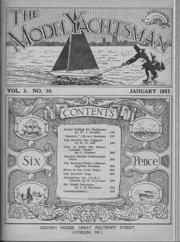
\\\ ae A a ane: > . ¢ ot, ’ st c O25 Etta oP anetacesete ness str g 823 ; Ca wi A WY (7 : 4 Z| “ O ; | 2. fe es as Ses ee : a ate ; y \ ‘ cf SH 5 : —— iy » ad WOON Efe: Model Sailing for Beginners by W. J. Daniels . … 195 ‘*Babette,’’ (36-in.) Sailplan 197 The Mounts Bay Luggers by H. O. Hill So ee How to built: the Launch ‘‘Helen’’ Steam by.J., Wallace Ree The Geo. Braine Testimonial as ae The Barnett Motor Lifeboat by3Dick Deadeye . Fund… i: 204 News of the Little Ships 205 Our Scottish Page ae . … 207 Measuring is i as : . : OFF la Batre: ~ j : Bas \ D) the I.Y.R.U. Classes, by W.H =Bauer 208 My Model Steamers by V. B. Harrison… 212 Correspondence eee yyy ar te WUCREMBMUMEURUCEMINCOUCRES ergsas DE (@2 /} SIF, OMS. (SeaS) ZZ f GOLDEN HOUSE, GREAT LONDON, PULTENEY W.1I. STREET,
a | | Model and ¥ | f Repair = First-class :: Service. Fittings :: without a blemish. T. MARCHANT, LTD., Sails Timber Merchants and Importers, Verney Road, Rotherhithe New Road, Steering-Gears & Accessories | PINE For Model Yacht Building. Up to 24in. wide, any thickness. Large or small quantities. This wood is Fit-out / Spars Vancouver WANEY i LONDON, S.E.16 1 i TO ORDER ONLY!! W. CAINS, | | OLD-TIME SHIP Model Yacht Sailmaker MODELS Built, Repaired & Re-Rigged One Quality only—the Best. ORDER. EARLY. eee ee Workshops: eeee 237, Goldhawk Road, 82, St. Edwards Road, Ne London, W.12 y, < GOSPORT, Hants. M.Y.A. SAILS NOTICE The Annual General Meeting of the Model Yachting Association will be held on Saturday, January 81st, 1931 Best Union Silk in 3 Grades in the Whitefriars’ Room, Anderton's Hotel, Fleet Street, London, E.C., at ee a ae al ll i Rl lk oe ee Yacht Yachtsman. 8-0 p.m. Flags €&? Pennants The attention of Members is called to the following: Retiring Officers and Oe Councillors are eligible for ré-election without nomination, but must be any size and design. included with the new Candidates in the ballot. SAIL CLOTH Nominations, in writing, in accordw ance with Form [, (see Rule Book), vow meeey must reach the Secretary four clear days before the Annual General Meeting. Nominations will not be Chas. valid ee unless signed by the nominee to the ety effect that he is willing to serve. West Hon. Secretary, 151, Lichfield Grove, Finchley, London, N.8 \ Drown, 8, Ullswater Rd., C. N. FORGE, 28 eee a —. Model [ VV. H. Bauer's { ' The AN — | 29 OR ET Te ERTS ae Te ee January 1931 J Norwood, S.E.27. .... In replying to Advertisers, please mention THE MODEL YACHTSMAN.
THE MODEL JAYACHTSMAN aS if ee ee ee ee eee fa rol. 3. MAGAZINE FOR MODEL MARINE ENTHUSIASTS. Ne. 0. JANUARY, 1931. MODEL YACHT SAILING FOR BEGINNERS. a MONTHLY eS A By W. J. DANIELS. yachting, alterations not that would sail perfectly. surprising that and wonderful. their efforts were often weird Apart from this, there was very little help coming from those of greater experience and even if it had been offered, the general attitude of the tyro was to want to solve the matter for himself. It is, perhaps, here that the greatest fascination of model yachting lies and many of the present day model yachtsmen prefer to adopt the attitude in keeping with the adage “she is a poor thing but she is all my own.” Much as this spirit is to be admired, little progress can be made if every generation has to make an entirely fresh start, and before you can design and build a yacht of any size with reasonable hope of even moderate performance, it is necessary that there must be a fair knowledge of the principles governing sailing. If these are not known, it is is erratic and not the model, unnecessary may be made in the latter with little has made many models the many hours of by rule-of-thumb method patient in an endeavour to produce a model effort over-canvassed and spent ¥ - writer - The > hope of improved performance. with the Most of the models were result not the hull was master. mistake of the beginner. was given to the result that the sails and This is the general No great attention accuracy in building or rigging, and was that the performance was seldom if ever the same on both tacks. also the common idea that a The writer had yacht sailed to windward through pressure developed under the lee bow, or that by getting greater forward grip either by means of the fin or greater drive up into the wind by placing the sails further aft was the solution to good windward work. Such ideas are of course, attempts to achieve by force what the model should do naturally as the outcome of the setting of the sails, and such attempts merely add to the difficulties as these features tend to make the model sail in a curved direction. from a perfectly designed and built model, How much less then is the likelihood of a beginner shape and general arrangement that tend to make having success with a model that needs considerable — practically impossible to get satisfactory performance alteration ? == wind that was scientifically pursued, the majority of Clubs proceeded on more or less rule-of-thumb _ lines Model yachts were built to the ideas of their constructors. As very many beginners started without the slightest knowledge of sailing, it is gu2 satisfactory, and unless it is realised when it is the were many Model Yacht Clubs in which the sport 2 Although there ponds, to which ete the present channels of assistance. the circumstances confine operations, are often far from — many years ago, there were not then open Even apart from all this, = model The right idea is to eliminate every feature in the model travel other than in the direction she is pointing. If at all angles of heeling, there is no — started ——————— writer 2 the eS HEN
196 feature in her shape that develops a steering effect it only remains to place the correct sail-plan in the proper position over the hull for the model to sail at a constant angle to the wind irrespective of its strength, the angle being determined by the angle that the sails are set to the centre-line of the model. The writer is fully aware that on many ponds, the proximity of obstructions cause an abundance of wind eddies, certain forms of keel will make the model hold the course irrespective of the influence of these eddies, and such a model will often be the more successful under these conditions, but such a model would be greatly handicapped on an open water where the wind is constant. The feature, that caused her to stop and shake head to wind and not lose her position, would on open water be a dead loss, as also would be her refusal to luff and take advantage of a free puff, and many models that are quite successful on their own particular water are outclassed when the sailing is under conditions of more steady wind direction. where The double-fin form of of January 1931 The Model Yachtsman. fins which consisted of varying areas placed in line model with the ballast in the form of a torpedo of lead connecting them at their lower extremities was very efficient in keeping the model straight, irrespective of change in the direction of the wind. a Once set upon their course, if the wind headed them they would wait until it again returned to its previous direction or also only very slowly pay off and fill. If the wind came free, they were a long time answering to the new direction although they would develop greater speed through being what is known as off the wind. This type, however soon lost its supremacy with the advent of the fin-and-skeg type but not until the latter had been brought to perfection. The present-day beginner has much more for his was available, Much guidance than ever before has been written upon all subjects with designing, building and sailing. in connection Modern and correct designs are available to him, and he need no longer start right at the beginning and wearily plod the path of disappointment and test of patience. The first and most important point of sailing that has to be tackled by the beginner is that of sailing the model to windward. Those readers who followed the recent America’s Cup Races will have noted that the failure of ‘“‘Shamrock V.” on this point of sailing prevented her from achieving her object. It is often assumed that good windward work is obtained at the expense of good reaching or running or vice-versa but it is the writer’s opinion that no sacrifice has to be made on any point of sailing in order to improve another point. So much is by way of preamble. The beginner will first require to be possessed of a model and if he has the right interest, will want it to be of his own production. The size and type of model wil] largely depend upon the facilities for sailing and his ambition. If he wishes to race, as he is sooner or later sure to, he will require a model to a recognised class. A small class known as five-raters was popular several years ago but have unfortunately lost its votaries, and no racing can be found now for this class. It may, however, be the desire to start modestly and it is advisable to make a beginning with a model built to a design that has already been proved. Many such have from time to time been published in the pages of this journal both in quality and size. The beginner must take care not to make the mistake of building a design to a size other than the designer intended as the same differences in relative dimensions have to be considered between say a twenty-inch water line and a forty-inch water line model as has to ke allowed for between a _ twenty-footer and a forty-footer. A consultation of previous issues will elicit the information which will enable the reader to carry out the construction, and if he is highly critical of his own work, and proceeds with care and patience he will find his due reward in the finished article. The great day of the launch is a thrilling moment even to hardened model yachtsmen who have built perhaps a number of models beyond their memory. Even though the work of construction and fitting-up has been correctly carried out, it still remains to make the final adjustments, and also to find out the particular demands of the model. Slight adjustments, which are impossible for the designer to provide for, may have to be made. The performance of the model may be made or marred by the way the rigging is adjusted. The setting of the sails may be greatly varied by the apparently small matter of setting-up the mast. The following should be the proceedure in rigging up at the pondside. The mast should be first stepped and the shrouds hooked on. The latter should be set up so that they bend the mast slightly aft and then hook on the headsail and set up the forestay so as to bring the mast forwardand straight. The mainsail should now be hoisted and the various sheets arranged correctly. If the boat and sails are new, the latter should not be hauled out on the spars too hard at first but to gradually do so as the sail is stretched naturally by sailing. A start should be made from the leeward end of the pond and in order not to waste time by getting the boat head-to-wind, or as is technically known as “in irons,” care should be taken to see that the jib is set closer in than the mainsail. This can be easily observed by holding the model so that the wind fills the sails and looking along the booms on the leeward side. The model should now be started by allowing her to sail from hand and the alterations necessary in trim may be diagnosed from her action. (To be continued).
January 1931 The Model Yachtsman. 7Q 157 OLN pee Be er SAIL PLAN OF “BABETTE.” (M.Y.A. 36-inch Restricted Class). Designed by W. J. Danters. The after leech of Mainsail has four Battons equally spaced. battens are 4ins. long and the intermediate ones 5ins. The top and bottom The lines of this fast and powerful little model were published in our | December issue.
198 January 1931 The Model Yachtsman. THE MOUNTS BAY LUGGERS. Part II. HE dimensions of sails and spars given in the first part of this article were taken one of the larger boats. Those for the smaller boats, were, of course, proportionately less. The foremast of these luggers was arranged so that it could be lowered when they were lying to their nets in a heavy wind, when they set a small sail on the mizzen to steady the craft. In order to allow this the mast was swung on the heel in a sort of tabernacle which was known as the ‘Scottle’. The scottle had grooves cut in the sides into which a very strong chock was dropped to prevent the mast coming aft. The heel of the mast was well rounded to permit the lowering. The first thing on raising the mast was to put the chock into place as otherwise the first plunge the vessel took, would By. H. O. Hin. All sails were bent to the spars including the jinny booms and topsail jinny boom by means of rovings (i.e. short pieces of line) at each eyelet in the sail instead of a continuous lacing. It should be mentioned that when the foremast was lowered it rested on what was known as the mast thwart, whilst the top of the mast would rest between the mizzen mast and its backstay. In order to permit this, the scottle or slot in the deck was slewed slightly to port. When the mast was raised or lowered, the forestay and jumpstay were used and it was at times even lifted right out by this means. The outrigger was on the port side, its heel being sufficiently far from the centre line of the vessel to have had very serious consequences. allow the spar to pass over the quarter and allow As has been already mentioned, there are only two working sails in this rig, the jib and mizzen was starboarded. line of the ship. the rudderhead room to come to port when the helm The outer end fell on the centre The fore-and-aft position was topsail being merely light weather kites, and this paucity of sails makes for an equal simplicity in the arranged to give the necessary steve to the spar so gear. sea. This simplicity made the lug sail in its various forms very popular with fishermen round our coasts and on the other side of the Channel. To this is coupled the fact that the dupping lug is a highly efficient sail that lifts the vessel along rather than presses her down. No wire whatsoever was used in rigging, Earlier boats had hemp but in later boats manilla was freely used. Coir was only only used for warps and buoy ropes where its elasticity was an advantage, but this quality would have been a disadvantage for stays or halliards. All blocks were rope stropped. Both masts had iron travellers for the lugs. The foremast of one of the larger boats would usually be about 7 feet from the foreside of stem to foreside of mast, the mast being about 10 inches diameter at the deck and about 5 inches at the head. The mizzen 7 mast was placed so that its after side was feet from the after side of the sternpost, the diameter being 9 inches at deck and about 5 at the head. The foreyard was about 6 inches diameter, big mizzen yard 5 inches, second 4 inches and the jiggers about 4 inches. All of these measurewents of sails are taken at the slings. ‘The yards were fitted with oak battens under the slings to take the chafe. The battens extended for about a third of the length of the yards to which they were lightly nailed and then bound with three or four seizings of spunyarn. The slings of the yards consisted of a grommet which was just long enough to allow one complete round turn on the yard in addition to the bight into which the eye was seized bringing the letter snugly on top of the yard. that it should not dip too far in rising to a steep The outrigger was often dipped. The exact position of the heel would depend on the height of the bulwarks which was usually in the region of 20 inches for one of the larger boats. ing it would usually mizzen mast. come a Generally speak- little forward of the In the open boats it fitted into a clamp on the after net-room thwart, and in the decked boats close to the coaming, but owing to the length of the cabin, the decked boats had their net-room farther forward. The heel clamp consisted of a metal strap and there was another where it rested on a chock on the gunwale. Reference has been made to ‘Jinny Booms’, this name was applied to the short foot booms (or clubs) fitted to the big mizzen and mizzen topsail and they extended about a quarter of the length of the foot of the sail. Taking the rigging in detail—on the foremast was the forestay, backstay and halliards. The forestay led from the masthead to a single and double block tackle, the double bloek being hocked on to the tack hook in the stem. This was only used with the smaller foresail (ie. the second mizzen) when the tack of the sail was made fast to an eyebolt halfway between mast andstem, The fore halyard was was single with an up-and-down purchase on the end. The halyard proper was known as the “Tye’, while the purchase was known as the ‘halyard’. The purchase consisted of a single block with a hook and a double block spliced into the tye. The lower block, which was a single one, hooked into an eyebolt in the deck just inside the gunwale. There were two of these eyebolts, one on each side,
Ithackle.four-bdmyingT,ws 1 9 3 J a u ry atshedaebcbokluvt,hwonufviw’s,pl‘theradneiypsawgtsouhlcmlikthde Yachtsman. Model The batocwTskhlnrfeudy. c(onbTti’ued). SCALE OF FEET 4 SAIL PLAN OF MOUNTS BAY LUGGER, 199
200 The HOW TO BUILD Model Yachtsman. THE STEAM LAUNCH Part IV. THe Binge Evsecror. HE bilge ejector is a very simple fitting and is clearly shown in the drawing. The T end is made by brazing the two pieces of copper tube together. The open end of the T piece is connected to the discharge overboard by a short piece of India rubber tube. The pipe soldered into the boat’s side should come close to the end of the ejector and be in line with it. The ejector is fastened to the engine bearers by small brass wood screws. THE Lamp. When all is said and done the lamp is the heart of the whole caboodle and if it is a dud then your boat is a dud too. The lamp shewn here gives an enormous amount of heat and less most lamps one sees. trouble than As will be noticed, it has no stay in it and so long as it does not take fire there is no necessity for one. The container never gets even warm and the pressure drops evenly as the petrol is blown out. The container is made from XXXX tin. The tan fet barrel plate is juggled at the seam and is rivetted with five small copper rivets. The ends were flanged on a piece of iron plate turned to the right diameter. The corners of this plate should be rounded off slightly otherwise it cuts the plate when flanging. After the ends are flanged they should be dished and soft soldered to the barrel. When this lamp was made it was very carefully T = 5.5 measured over the end plates. was pumped into There was no it and it Then 80lbs. pressure was measured again. difference in length which showed that the end plates had not bulged in the least. The pressure was left on for twelve hours and only fell one and a half pounds. This was. no doubt, due to the very slightest leak in the fittings. The nipples are No. | Primus, but then the writer has taps for these. If you cannot get hold of a set of taps it]is better to use ‘* Aetna” nipples which January 1931 “HELEN.” By JoHN WALLACE. are screwed }” diameter x 40 T.P. 1”. The nipples have to be opened out, this should be done gradually with a watchmakers reamer, you can buy one for about threepence. It is well worth while to spend a little time trying the lamp, then opening the nipples and trying again until you get it right. The burner tube is made from XX XX tin lightly rivetted. The back end is cut to form tongues and the back plate is fixed by bending half of these in front and half behind it. The size and position of the air holes was found by experiment, much better results being got by having a number of small holes than was obtained by having a few large slots. The present arrangement is very awkward if you want to prick the lamp when it is hot, but the writer puts up with burnt fingers so long as he can get a real hot flame. These tin tubes burn away very rapidly, so when making them it is best to mark one off and then from that drill about six of them all at once. The back plate can of course be used indefinitely. No detailed drawing is given of the needle valve on the pressure tank because it is the same as the feed bye pass valve except that instead of taking the pipe across the bottom a boss is formed and the pipe is screwed into it endwise. The valve is just soft soft soldered into the tank. The copper vapourising coil is quite ordinary and is fastened to the tank by two small tin clips soldered on. The fillmg plug and combined. air pump connection are A Primus air valve being used but this is a refinement and an ordinary tyre valve is just as good. The only trouble is that you have to change the rubber tube every time. The tank is pumped up to 60lb. to start with and except in competitions is allowed to blow all the petrol out without further pumping. The lamp burns very well although not quite so fiercely as at full pressure. (T’o be continued). **Helen’s”’ Port Plant Side
a SS 710 Vy : jp Sheer Teel gudpears: stil Fig 34 Brasslump ® Bree Sra.5S aoAbrtetire rs lamp Tram Te Se Left gaye =) Set 2 + sit —— ke =—$-te . or { = = eecat gaia la Sy wuut i cs eee TP. ee . ih ‘me Hui BY. —__ I Wa a4 Ro + @ al : to * ses Sucdcon/Pipe sent bw / | = | leat 2 2 ae TFS Ze Semel )(aN ‘ Brass Suclcon Pope #9 35 +4 aa ae . i= yaa : — Brass Feed Pum fp 209 33 lo Va. Lf N7, ae = tafe | am J rI2L rf 3S MS. 012 Pam jp Link eg 33, Sztver Stee? O12 Pump ‘UBUIS}YIeX jepoyy ey] S . ARNT yee Hexagon 3 ra00 “ “mle idl A DE nt ka M.S. Thrust Codlar veg 37 Lope Thrust Ball [Pace 44 Ao off Engine Deraits. Saeer N2 4 106 ae 1g6] Arvnure £. clin Sema 40 TPL. Mb | fa Taha Heedprpre mance weil ae ca
Ry bale. I¥\* % : Sereued 4 dua boTPt d =o) as d* | $ ~— mee SheLh 3 mise clea SD. Coppsr tube x Wb : Yo Se ABN y Foner a + [gare corte tala eS aT Brace Siny My ore ha surg, ‘ Sra Plates N2/2 sug Coffer in Pop ‘ Jukes £. fina oemx t aihe- dala. SD eofsfaen g” ee >| of – . – 4 Back End Plate = ® af ILE ‘ : x ) ~ gE ie “ G4 8 ) fe Feed Mech Melee: Pep de Serewed x Sys Selede ae wt fF OR Seed “ iF ; Stam Pipe |; > L Leff ee Gul bt Feed Zee. rae os LS ao 7h. mg iz Th lay |


