- Title. Author. Summary

STRICTLY SAIL BY ROD CARR TUNING & SAILING GUIDE TI he following is the third and final part of the “Tuning a 12” series of columns by Rod Carr, which originally appeared in a span of 15 issues of the monthly newsletter of the Greater Seattle Starting position, during a race if need be! Now is the time to simplify your boat and its rigging. The result will be reproducible settings, and more time to focus on sailing the boat rather than building it at lakeside. Model Yacht Club in 1988 and 1989. If you’re just com- Main boom vang* Jib Halyard* Mainsail Halyard?* Main Clew Outhaul Main Sheet Jib Topping Lift *Turnbuckle —* Bowser ing aboard and missed the firsttwo installments (Fall and Note that | have made no provision for moving the FIG. Winter 1991 USB&SM), back issues are available—see the USB&SM subscription ad on page 39 in this issue. foot of the mast back and forth on the deck, or raking the mast fore and aft, or any ALUM. MAST CLAMP PART XVI: RECOMMENDED RIGGING of the other 1001 “neat” things you’ve seen done on a big boat. Complexity breeds slowness, and makes MAIN BOOM itimpossible to reproduce a While inspecting boats in fast configuration in the fu- our fleet | occasionally find a ture. M2. rigging method that is worth discussion. | recently discovered a boat in which both the top and bottom ends of the jibstay were made from dacron sheet line, while the PART XVII: RACING DISPLACEMENT Having taken part in the measuring of the local boats te 5 intervening jibstay was of that would be journeying to Kewanee, Illinois for the 1990 ACCR, | had the op- standard rigging. One might think at first that such an arrangement would be good, since the length of the jibstay could be changed from either end, allowing easy adjustment of mast rake. No doubt the adjustability is there, but it is offset in my opinion by the requirement fortwo more cleats, and the possibility of failure of four extra “joints” in the system. Knots seem to ‘have a hankering to let go, portunity to listen to amany- 1/8″-3/16″ DIA. BRASS MAST East Coast 12 meter. The ab comments have equal applicability for either the AMYA version or the Inter- : Sr ~a end of the jibstay. Either or both of the cleats could let go, and the one additional Recommendation: consider the simplicity and trustability of a single jibstay swaged to the forward end of the jib club, and swaged again at the mast. Can’t adjust the rake, you say? Don’t bother with it, say |. Anything mast rake does can be done better and quicker with the jib sheet, and the jib sheet can be returned easily to the 2 SPRING 1992 national version. Recall that when the class obtained the original design drawings for the Morgan Plug, we gained clear evidence that the de- and with the system | discovered there was one ateach up on the mast provided windage. Sabie sided discussion about the proper displacement of the U.S. BOAT & SHIP MODELER sign waterline was 42.5 inches. Subsequent med- If a fitting is adjustable, it must have moving parts of some type. Anything that has to be movable is more likely to break than something that is fixed, so adjust only those things that are absolutely required. | would list the following as movable once the rig is set up on the deck: Side Stay Turnbuckles* Backstay Tension* Jib Clew Outhaul Jib Sheet dling with the AMYA class rule has expanded that to a range covering 42 to 43 inches. While the length of the LWL is important as a determiner of top hull speed available while sailing in the displacement mode, of equal importance isthe location of the LWL plane in the body of the hull. It is obvious from the Morgan drawing that the LWL plane is to be parallel to the bottom of the aft portion of the keel. So if one blocks up the hull on a level surface, the 43-inch maximum LWL exists
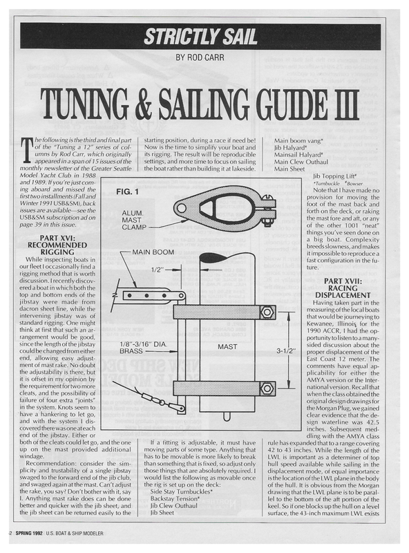
as a plane, parallel and above that surface. No AMYA authorized manufacturer has ever gotten a scribed waterline coincident with the design intent. The easiest way to locate the LWL is to use one of the “calipers” that have been built to locate the extremities of the LWL on the centerline of the hull. Those marks then can act as a guide with the boat in the tank for final ballasting. What is the best place to ballast to? The consensus seemed to be in the 42.5->43- inch area. Most of the reasoning for being a bit below the maximum allowed was based on being sure that anyone measuring the hull would find it to be legal. There was some growing sentiment that at 42.5 inches there was a compromise between nimbleness for tacking and stiffness for heavy weather sailing. After all the theories were ad- vanced, agreement was reached on one key issue. A half inch of waterline length means liter- and weather helm. Jib trim: Flatten your jib and then trim it for maximum pulling power when going to weather. You will have de-powered the mainsail under the previous directions, and it is impor that tant the jib be producing as much power as possible. Don’t try to point excessively. Sail slightly free so that the jib can power the boat through the waves. In heavy gusts, trim the jib in to balance the main and prevent the boat from rounding up. Winch handling: Unlike light air, where sails can be trimmed and almost forgotten, in heavy air the winch must be continually played. Don’t take your thumb off the stick; coordinate the rudder and the winch to work the boat through the gusts and waves. Slack both sails in the gusts and head off for boat speed. Point back up in thereby avoiding the need to drill holes in the aluminum extrusion. The goal was to keep the stiffness of the mast intact so that it could take up an even bend under the strain of the backstay. The evenness ofthe bend was valued by sailmakers who could make sails that would be a good match for the mast and which would be able to work with the mast to match the changing wind strengths. The theory seems to have been borne out, if the large percentage of boats in the AMYA and the International Class that use the aluminum mast is an indication of the success of the approach. Over the last five years, competition in the East Coast 12 meter class has reached a level which would not have been pre- dicted in the earlier days of the class. Skipper skill and the tighter rules encouraged by IMYRU has driven the class toward the objec- tive of having the boats “as alike as FIG. 2 reasonably pos- sible.” Asaresult, differences in rig- ally ines ses compared to ging and the re- the impact that the skipper can haveon the boat and how it is sailed. Ome ie Si bn @EESER sulting impact on sail shape and boat speed have become more cA Hnportant than efore. PART XVIII: HEAVY AIR Early advice recommended COMPETITION Having sailed for three days in heavy air with gusts to 30 JIB CLUB (oe) JIB SWIVEL 1990 AMYA EC/12 learned with the EC/ 12 are worthy of re- Boats wearing that suit finished second and fourth at the ACCR, one set from Sterne and the other from Carr. The reduction in heel and the ability to flatten the head effectively seem to make this cut inherently a better match for high winds. The International EC/12 A-Rig fits within the AMYA EC/12 rule, so one suit of sails allows you to sail in both classes. Mainsail trim: Careful attention to mainsail trim is necessary to keep the tender EC/12 on her feet. Make sure you have plenty of trim movement available from your winch, and trim the mainsail out, off the centerline of the boat to reduce heeling. The vang needs to be tight to prevent the sail from twisting. The higher the wind, the more the main should be trimmed out. This will reduce both heel much asmate5 rangement made ACCR and at a Gig Harbor Club regatta, some lessons Sail type: Substantial benefits seem to accrue from the conservative mainsail roach on the International EC/12 A-Rig. main boom as inches aft of the aS teaibe clle and above at the peating. | that gooseneck fittings pivot the the lighter stuff to regain distance lost to windward. When reaching, slack the sheets to prevent round-ups, and when going down wind, a wing-and-wing configuration will balance the boat quite well. Watch out fora rounding-up to the side that the jib ison. The power in the mainsail is awesome and the rudder will not counteract it. Anticipate a round-up and correct with the rudder early. Once an EC/12 heels and sticks her main boom in the water, it’s all over but the shouting. PART XIX: GOOSENECKS REVISITED About 16 years ago, an article in Model Builder magazine described the kinds of fittings that have become common in rigging the GoldSpar aluminum mast. The jibstay attachment, spreader attachment and gooseneck fitting all shared a common design theme: they were all metal collars that clamped around the aluminum spar, for increasing camber inthe sail as the boom was carried outboard on the reaching legs of the course. While more power could be obtained from the mainsail, some of this power would appear as a force trying to round up the boat on the reaches, requiring rudder offset to counterbalance. Over the last few seasons there has been a definite trend toward flatter sails in the class. This has been accompanied by a reduction in the distance aft of the mast that the main boom pivots. Now, 0.5 inch or less seems to be optimal. Of increasing importance is the engineering of the gooseneck to maintain control of the mainsail leech twist using the vang. In Figure 1, one sees a Current ver- sion using a brass axle holding both the main boom and the vang on a common pivot. The common pivot approach helps main the alignm ta ent in ofthe mast clamps, which is essential to free rotation, as well as control of main leech shape on both sides of the boat. The holes through the upper surface of the mast clamps are U.S. BOAT & SHIP MODELER SPRING 1992 53
countersunk, and just before sailing, a little sewing machine oil is dropped into the depressions formed to let the axle rotate easily. While aluminum is a favorite material for the upper mast clamps, brass is preferred for the gooseneck so that there is compatibility between them and the axle. A couple of experiments with ball bearings mounted in the mast clamps indicated that a simple brass/brass sleeving with plenty of lubrication is simpler and lighter. A word on construction of the mast clamps. First, drill a 3/8-inch hole in the stock, file it out to slide snugly along the mast, cut into the hole on the bolt end, then lay out the rest of the piece. It’s kind of like shooting the arrow into the side of a barn and then drawing the bullseye around it. Slide both mast clamps onto a stump of mast stock and drill the axle holes at the same time to ensure alignment. PART XX: JIB TRIM FOR POWER AND BALANCE The procedure for setting a jib begins with: Slot—open at foot, jib leech follows main leech. Start with four knuckles at club; set the trim lever on the transmitter in the middle of its range. Leech shape must continue to match the mainsail on reaches, without downward pull of the jib sheet. Make sure the offset is as shown in Figure 2. The longer the offset, the harder the jibstay will make the leech, i.e., the better it will hold down the aft end ofthe jib club. Jibstay tension is directly a function of backstay tension. Backstay offset or the jib topping lift after reaching along the course to and from the wing mark. Many skippers using the Sterne sails have fitted a topping lift to the aft end of the jib club. This line provides a counterbalance to the tension of the jibstay and can be used to soften the jib leech. The tension is a result of the kind of mainsail you have. A Sterne mainsail will have plenty of luff round and the mast will have to be bentto match it, hence more backstay tension, and therefore more jibstay ten- problem with snagging the topping lift on the spreaders can be addressed by includ- sion. Less offset will be required of the jib swivel, since the jibstay is pulling harder. A Carr mainsail will have less luff round, backstay tension will be generally reduced, and less offset will be required for the jib swivel to allow the jib leech to assume the ing a stretched rubber band between two places on the topping lift so that if the jib club lifts and slacks the lift, the rubber band will pull it taut, keeping it from snagging a spreader. PART XXI: SAIL FABRIC SELECTION proper shape. It is the jib sheet that gives most of the control of jib leech shape while sailing close hauled. But when the boat is off the wind on a reach, the offset must be correlated to the amount of backstay tension that is being carried by the jibstay. To work on this, place the boat on its cradle, block the cradle to incline the boat, and turn the cradle to let the wind fill the sails, which should be let out about one-third of the way. Adjusting the settings in this manner is an approximation which must be eventually checked on the race course, underway. Top skippers are usually seen to launch their boats before a regatta and make adjustments to either the East Coast 12 Meter sails are made from a number of different materials. The choice of material may be left to your sailmaker, if he is familiar with the water that you sail on and its peculiar wind conditions. If you intend to order sails from a model yacht sailmaker who has not sailed your pond, some additional information will help both of you make a decision that is optimum. Let us confine ourselves to consideration of the standard full-sized sails represented by the AMYA standard rig, and the International EC/12 Class A-Rig. Smaller suits such as the AMYA Storm Rig and the B-Rig and C-Rig options offered by the International EC/12 Class Rule will be AMERICA’S CUP STRIPES CAT & OTHER RADIO SAILER KITS FROM $150. 92, STARS 12 METER & & discussed another time. You must analyze your sailing site for: A) The average wind speeds encountered each month; B) The kind of wave action existing on the pond. SS t Wind speeds can be monitored with a \ Fa valable U.S. NAVY Dwyer “rising ball” anemometer or any of the more expensive digital wind speed meters. At least one person in the club WW II DESTROYER should have one in his tool box. In your log book, note the highest and lowest wind speeds encountered, and the average for each of your sailing days. Waves are defined as repetitive hills of water that cause sufficient hull motion to move the upper third of the mast ata speed greater than the existing wind speed. i.e., if the wind is blowing 2 kts. and the 6-inch tall wake of a passing motorboat causes the boat to move enough to shake the wind out of the sails, then those are waves. 1/700 Plastic Waterline Model A classic collectors edition, for 10-year-olds to adults. Something special and long overdue for the serious model builder. Best plastic available. Finest attention to detail. History and specifications included. Made in the U.S. $11.95. Postage prepaid. | | Send this ad & $3.00 get 16 how-to plans, color photos, prices & catalog f FAX (516) 842-6353. Complete line of | | Sailboat hardware all nylon, stainless, aluminum & mylar. U.S. fl to: Pop Up Mfg., 27 Emerson Ave., Amityville, NY 11701. (516) 842-9309. 54 SPRING 1992 U.S. BOAT & SHIP MODELER { SHIPS UNLIMITED P.O. Box 582333, Tulsa, OK 74158 [ Please send_.___ (indicate quantity) f GEARING/SUMNER 1/700 Waterline | models @ $11.95 ea. or 2 for $21.95. My check/money order is enclosed. Name Address City/State/Zip | | | cas! But if the wind is blowing 20 kts. and the boat never moves violently enough to shake the wind out of the sail, then 2-foot seas are not waves for this discussion. Selection of sail fabric depends on knowing the average winds you sail in, and what the surface of the water is like. Should you sail exclusively in small, landlocked ponds, such as the one the 1990 AMYA EC/12 ACCR was sailed upon in Kewanee, Illinois, you may never encounter “waves,” even though the wind blows 25 to 30 kts.! There is simply not enough fetch or length of water to allow the wind to start piling up the water to
make waves. But if you sail on a larger body of water, such as GSMYC’s Juanita Beach site, even moderate airs in the 5 to 10 knot range can build substantial hills in the water which must be taken into consideration when choosinga sail fabric. In general, the mylar fabrics seem well suited to the lower wind ranges, the exception being very lumpy water where the Dacron variety holds its shape better without crumpling under the whipping of the mast as each wave causes the boat to pitch. The stiffness of the Dacron doesn’t let the sail collapse, and the Dacrons that were doing the best were of the single panel variety with broadseam shaping. PART XXII: HEAVY AIR PRACTICE Here in the Northwest Racing Circuit clubs, both IEC/12 and AMYA EC/12 race together in a single fleet. This provides skippers with the option of experimenting with the B and C rigs provided by the International EC/12 Rule. But the experience at the AMYA EC/12 ACCR for 1990 showed that after some forced practice, the boats can be sailed in steady winds above 14-15 knots with the full-sized sails. The AMYA storm suit is so much smaller than the standard sails that no one was willing to change down to the storm rig for fear of being handicapped if a lull occurred during their heat race. So we have really two efforts that can be made as we enter the windy season. First, consider the purchase of the B-Rig from your sailmaker in either Dacron or 1.5 oz. Mylar. The rig height is reduced by 20%, rapidly decreasing the heeling experienced by the hull. Down wind sailing is almost totally lacking the forced rolling and rocking from side to side seen with the A-rig. Broaches are easier to control, and can be prevented with rudder control as long as you keep on top of what is happening. Remember that the turning force that the rudder is able to exert is steadily reduced by geometry when the boat heels. With a 45 degree heel angle, the turning force is reduced by 30% and turbulence and air bubbles are conspiring to reduce its efficiency even more. The best time to learn to cope with heavy air is by yourself. Go sailing on your local pond when the weather is bad enough to stay home. Find out if anything will break. Practice tacking and jibing. Pull the jib in a bit to backwind the mainsail and help hold the bow of the boat off the wind. Flatten both sails, and then slack the vang a touch to let twist develop in the mainsail. As muchas the top third of the main can be luffing while the bottom is providing useful drive to the hull. A good drill is to bring the boat up into the wind and get it into irons on purpose. Let the wind push it backward and hold right rudder to cause the stern to round up to starboard; when 56 SPRING 1992 U.S. BOAT & SHIP MODELER the sails fill, center the helm and go forward on starboard tack. Practice luffing the sails while keeping the heading of the boat constant. In heavy air, never take your finger off the winch stick. Be ready to slack the sheets in the heavy puffs and drive the boat off for added hull speed. Practice all these things before you get to a regatta and you’ll be surprised at how far up in the fleet the lessons you learn will propel you. PART XXIII: RENOVATION OF OLD BOATS Once in a lifetime one gets a chance to do some real historical detective work. Such a chance came my way in discussing the renovation of US 51 with Mike Gib- It is the jib sheet that gives most of the control of jib leech shape while Sailing close hauled. bons. Number 51 was one of the original boats in the class, having first belonged to Mike’s late father. She represented the look that the early boats had, which was often described as “swaybacked.” When Mike decided to replace the deck on #51 this winter, | jumped at the chance to help. With the current confusion about AMYA EC/12s versus International EC/12s, #51 gives us a good benchmark for comparing the two. Number 51 is definitely related to the original EC/12 towing tank model, usually known as the MORGAN PLUG, having come from the same mold that produced #25 “FLAME,” which was the plug used by Dwight Hartman in late 1971. When #51 entered the fleet in 1988, she had the usual teething troubles encountered in breaking in a new skipper and finished 21st out of twenty-one. New dacron sails and some equipment modifications saw her finish the 1989 season 14th out of twenty-nine. In the 1990 season, with some new Micafilm sails aboard, she jumped to seventh out of twenty-seven. The boats finishing above her consisted of four OZMUNs, one TREASURE TOOLING and one DUMAS. The conclusion is that the skipper is making the difference and a 22-year old EC/12, even with a 13inch beam, is as competitive as the person helming her wants to make her. When we took the old deck off we discovered a written inscription indicating that the hull had been taken from the mold on January 8, 1969, and had originally been consigned to Bert Lott of Florida. This makes her just short of 22 years old. Careful measurements of all fitting locations were taken and special- emphasis was placed on the sheer beam measurements taken at 5-inch increments from the bow. The boat was originally built with a maximum deck beam just shy of 13 inches. But remember that the hull was outfitted and afloat before there was either an AMYA or an EC/12 Class! Even more amazing was finding that the entire deck structure, the beams and the sheer clamps were made of balsa! That she held together this long is a tribute to the gentle care she received from her owners. A final twist was learning that the boat was not molded with a fiberglass transom, but was fitted with a separate one of mahogany. Next we accomplished a wholesale cleanout of the interior of the hull. We then fitted a 1-inch square pine stretcher bar inside the hull from bow to stern. The stretcher pushed both the bow and transom downward, which caused the sheerline to move in toward the centerline. We worked the beam in to 11.5 inches which was the original class specification, and installed 5/1 6-inch square cedar sheer clamps liberally bedded in thickened polyester resin that was mixed to take an entire week to cure for maximum strength. No wonder she looked so swaybacked, for when the midships beam was allowed to spread to 13 inches, the bow and stern both rose to such an extent that the front half looked more like Saddam Hussein’s slipper than the business end of an EC/ 12: The next step was to fill my test tank with hot water liberally dosed with a few teakettles of boiling water. By heating the hull and letting it float, some major dimples disappeared from the hull. She had been sitting in a cradle for 20 years which had not properly supported the lead. The dimples are a thing ofthe past. While the hull was warm, we reinforced it on the inside with a layer of fiberglass cloth from the top of the keel cavity to the upper topsides. The hull only weighed two pounds as it came from the mold. Such light construction, as well as the brittleness which seems to eventually infect polyester materials that are exposed to ultraviolet light, made reinforcement important. The boat is scheduled to take part in a very competitive fleet and occasional contact with other boats is guaranteed. Now we are ready for new mounting blocks for the radio gear and sail control unit. Next will be deck beams, back-up blocks for chain plates, mast step, backstay and jib swivel, and then a 1/16-inch plywood underdeck with West System epoxy on both sides. Finally, a strip-planked outer deck of fine grain fir will be applied, complete with black caulking stripes between each plank. Cosmetic repairs to the hull’s gelcoat will precede a general fairing, then primer and paint in a blazing new crimson color scheme to be chosen by the owner. And | predict she will be even faster than she looks!