- Title. Author. Summary

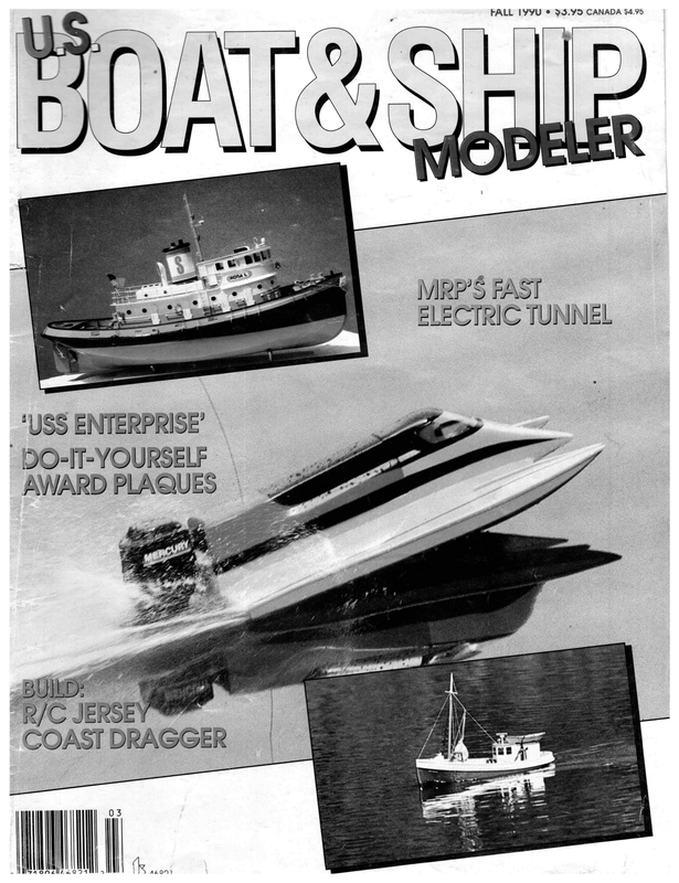
FALL IYYU ® 95.99 CANADA $4.95 ‘USS ENTERPRISE’ \ ” 1O-IT-YOURSELF AWARD PLAQUES — R/C JERSEY COAST DRAGGER WN. WACNLNL LOD
BY ROD CARR nly occasionally have we been presented with some kind of summary description of activity and trends in the International Classes. As we embark on a voyage into the 90s it seems sensible to stop and take stock of where we have come from and where we might be going in the popular Marblehead class. We will call upon such luminaries as Priest & Lewis, Roger Stollery, Gerhard Mentges, and Bob Sterne to show us the past line of development and predict where it might lead. Before we begin, it must be made clear to American readers that the American Model Yachting Association does not accept the International Marblehead Rule. AMYA has a written policy of isolation from the International Yacht Racing Union—Model Yacht Racing Division (IYRU-MYRD) which prevents American skippers from configuring their boats in compliance with the rules accepted by all other countries taking part in model yachting around the world. The reason presented for such shortsightedness is that “we want to retain control of the class.” Control AMYA may have, but by so demanding it has effectively isolated American skippers from the mainstream of development in the class. This position has garnered for American skippers avery poor reputation in the international community. We are seen as isolationists, unwilling to abide by world class rules. It has even been hinted that we are possibly just not able to hold our own in international competition and therefore have opted to hide behind our own borders! In addition, such an ill-advised policy perpetuates an AMYA rulemaking procedure which totally ignores the welfare of the great majority of its skippers. The outmoded AMYA procedure allows only two skippers to propose rule changes without consultation with their fellows, discussion with the Class Secretary. There is no opportunity for a reasoned determination that the (inset) KMS “Cobra” multi-hull, 48-inch long main hull, dagger board and rudder. Available through KIP Marketing, 33 Yorke Gardens, Reigate RH2 SHQ England. Could this be a new class? (Right) Note the wake in light air. No lead ballast to drag along! 34 FALL 1990
° FicuRe 4 BRITION MARBLE BEAD 3h MAR OLEREAD DESIGN TREN OS E : a = | DepacemeNnT(lbs) Ss BS & oY oe ro Dis PLAcemen T Be : oo Fe.2 | BRitisH ae? i. eS 1470 cio. as 2 YEAR 1980 es Figure 1. British Marblehead Design Trends. proposed change is good or bad for the class. You and I, all by ourselves, could put a motion on the ballot to paint all M-s pink! What mischief. Having recently taken a three year side trip into the arcane world of rule writing with the International East Coast 12 Meter Class, I can say that the greatest majority of the class rules that have been authored by Americans are of dubious quality. Rule writing is simultaneously an art and a science. Amateurs who try their hand inevitably produce amateurish rules. By working with knowledgeable and experienced people from many countries, [YYRU-MYRDis able to produce International Class rules which are consistent and based on many years experience with yacht rating as found in the parent body IYRU. Why AMYA officers would think that there was something to be lost by tapping into this experienced resource is beyond me. The potential benefits seem obvious! Even worse than perpetuating unproductive procedural rules, Ihave obtained unimpeachable evidence that the current AMYA administration has interfered in the publication of the Quarterly Newsletter in a manner that has actually violated the 1st Amendment rights of the members for a free press. They actually forbade the publication of letters to the editor which were critical of how they were managing the organi- zation. Where this shameful practice will lead I don’t know, but I would imagine that replacement of this misguided pack of scoundrels with a new group that protects freedom of the press would be a good first step. Apparently it is now OK to tell Gorbachev what you think of him, but f 10 “Okey” 334 DEscn aah EP 77s Kee Depry Civcuss) s arsine eeMELY ww «(CC = oo as oe i880 igs L 190 Figure 2. British Marblehead Design Data. one can no longer comment on the foolish policies of the AMYA President in the AMYA Quarterly! IfI put on my red satin turban, and assume the identity of “THE GREAT CARNAK” (with apologies to Johnny Carson), I predict that the pendulum is swinging in the other direction and a new slate of AMYA officers and directors will set the organization on a wiser and more productive course. You heard it here, first! Having said all that, let us proceed without further reference or concern for the AMYA’s shortsighted policy. No organization has the power to truly get in the way of individual skippers and our enjoyment of the sport. At most, such interference is a minor and temporary embarrassment to the supporters of the hobby. In preparing this article, I was given so much excellent support by the various designers that it grew too big for printing all at once. I have prepared it in two installments, with the second to be published in the next issue of U.S.B & SM. My sincere thanks to all the contributors. This is what model yachting is all about! MARBLEHEAD CLASS DESIGN TRENDS—1990 AND BEYOND As most folks know, the Marblehead class was a purely American invention. In 1930, Roy Clough, of Marblehead, Massachusetts, developed a 50-inch long boat with a length tolerance of plus/minus a quarter of an inch and with 800 square inches of measured sail area. The jib hoist was to be no greater than 80% of the height of the total sail plan and at the midbody at the garboard, where the hull blends into the keel, a one inch radius minimum was set. The class was established as a means of filling the gap between the existing classes being sailed at the time. It also was an answer to the complicated for- mula that controlled the design of the International A Class and International 6 Meter. To develop a boat in these classes, one almost had to be anaval architect by training, whereas the simple Marblehead rule was intended to encourage amateur design and building. PRIEST AND LEWIS (1956) Comments by Dick Priest and John Lewis in their classic book, Model Racing Yachts, provide some interesting insight into the early applications of the rule in England. I quote: “As with all new rating rules, the first problem confronting the designers to the brand new rule was just how big to make the boats? It is usual that the original boats to all new rating rules are too small, and because of this are completely outclassed in a couple of years. The Marblehead Class was no exception. In fact, not so long ago the writer met a gentleman who had recently come across Marblehead K.1 (Note: The first Marblehead registered with the British Model Yachting Association). According to his account the boat was like a small edition of a 10-rater and had about a 36-inch waterline, drawn out in overhangs fore and aft to give the overall length of 50 inches. Her displacement was in the region of 12 pounds… It did not take long for designers to realize that Marblehead K.1 was too small. At the same time, however, it must be remembered that between 1937 and the outbreak of the war there was no Terylene (Note: Dacron to us) sails… and sail aspect ratios did not go to present day limUS BOAT & SHIP MODELER 35
its. A typical example of a successful prewar Marblehead would be the Edwards designed MYSTICO. She was 16 lb. in displacement on a waterline of about 45 inches… The American has always been anything but conservative in his outlook and this trend was very evident in the immediate postwar designs in this class. They experimented in the wildest possible range, from sail plans to keel forms. Some of the latter even consisted of a thin fin attached to the hull halfway along the run. From this lead ballast extended forward in the shape of a torpedo. Incidentally, this form of keel was later banned. Hull forms were, in some cases, terribly slim with deep vee sections and used every single fraction of the 50 inches as waterline length. The hull forms in many cases were quite unbalanced. “Experiments in the British Isles were not so ‘wild,’ but did reach a maximum in a 31-pound boat developed for use in the northern winds by a Mr. Bostock. The early wisdom said that Marbleheads should havea displacement of between 16 and 30 pounds.” Two things should be noted from this discussion. First, early Marbleheads under the influence of short rigs had displacements down toward the lighter end of the spectrum. K.1 was a 12 pound boat, a weight that would have put it only 3/4 of a pound heavier than the boat which won the 1989 British Championships. Second, in the period from 1930-1950, the Americans occupied a position of influence in the design and sailing of the Marbleheads. We had a reputation for innovation, and a demonstrated willingness to contribute to the international yachting scene. The preceding discussion dealt with free sailed models, R/C was not yet being applied to sailing models. The designs and the displacements were calculated to provide boats that were put on course, and then were supposed to stay on that course. Longitudinal stability, the ability to maintain a direction under a constant wind, was a primary design goal. Substantial attention was paid to hull form and appendages such as skegs and keels which were quite long in the for and aft direction. STOLLERY, BANTOCK AND DICKS (1985-86) The next major statement about Marblehead class design occurred well after the R/C era was underway. Roger Stollery, of England, has been involved with the class since the early 1960s, and over the ensuing period 36 FALL 1990 he has had the discipline and foresight to collect information on the boats which have appeared in the regular series of British championships. In the March 1986 issue of Model Yachting News, a detailed article appeared which was a collaboration between Mssrs. Graham Bantock, Roger Stollery, and Chris Dicks. Among the novel items which appeared was a clever adaptation of typical design drawings, in which Roger started drawing 50-inch Mar- blehead hulls with the longitudinal axis foreshortened by a scale of 1:5. The subtle curves of the profile and plan views of the hulls sprang into obvious view, and it was possible to produce a complete hull drawing on two sheets of A4 paper (something very near the 8-1/2 x 11 we use here in the states). Accompanying the article was data on the boats which had been taking part in the British M-Class Championships from 1960 to 1985. Roger has recently updated this information to include 1989 and all the data is provided here as Figure 1. Notice that the boundaries of the envelope between maximum and minimum displacement have been smoothed by some arbitrary curve fitting. It is the trend that is of interest here, though individual data points have been plotted for reference. Displacements of individual boats in each regatta is marked. Typically arange of displacements of five to six pounds is represented within the fleet. In general, one can conclude from the plot that when the occasional heavy air regattas have occurred, heavier than average boats have won. In lighter air regattas, itis the lightweight boats that have done well… notwithstanding the sometimes overriding influence of the skipper in handling the boat in the conditions faced. Previous comments published in the AMYA Quarterly by Karl Kirkman, designer of the BONE series, have explained the tradeoff between momentum and acceleration in favor of the lighter displacement. Also included is another plot (Figure 2) that shows the progression of keel depths that has been observed in the British Championships. The trend is obvious, and the depth to be experienced in the next few years is precisely as predicted by Bob Sterne in the second installment of this article. Roger’s 1985 discussion did not point toward a continually decreasing displacement with a steady deepening of the keel fin. Both he and Graham emphasized the importance of taking a “systems” approach to design and building, feeling that the proper integration of hull form, keel depth and weight, and sail plan handling were required. Optimum performance on all legs of the course was stressed, rather than giving undue importance to the ability of the boat to perform on the.windward legs. Very important were considerations to be made on changing rigs. If the top suit caused one to change down because of its influence on the hull when sailing downwind, even though the top suit could still be carried effectively to weather… then one had gotten into a situation where the separate parts of the system had not been integrated. The goal would be to change down when performance on all legs suffered, so that under the lower suit, performance was still maximized on each leg. Maximum draft was approximately 18 inches at the time, and neither designer predicted that near term developments would lead to a rapid deepening past that value. Subsequent work added an inch or so by 1989, but this prediction has been borne out by most new designs reported in the literature. MENTGES 1987 Gerhard Mentges has been model yachting since 1973, starting as a member of the Duisberg Ship-ModelClub. He studied Naval Architecture at Aachen University and started work as a development engineer in the Department of Hydronautics at AEG in Hamburg. In March of 1987, Gerhard commenced a four-part series in Model Yachting News on Model Yacht Design. The series began in a general manner and rapidly moved directly to consideration of Mclass hull design, as would be expected of a trained hydrodynamicist. Part 1 dealt with an introduction to the field, and discussed hull and sail forces with an emphasis on hull resistance. Part 2 focused on hull issues such as longitudinal stability, freeboard and beam. Hull shapes like the radial hull, trapezium hull, vhull, and u-hull were explored in quite a bit of detail. Each shape has benefits and disadvantages, depending where along the hull it appears. Part 4 concludes with specific directions for developing a trapezium hull that optimizes the considerations presented through the series. While rather technical, the series is a major contribution and should be required reading for any designer who wants an approach based on the physics of the liquid in which the hull sails.
Gerhard says that subsequent chapters will be forthcoming and will deal with the fin/bulb combination. As of this writing these have not yet been published. e r a n Noe ADRIAN BREWER 1989 One of the leading Australian de- signers is Adrian Brewer of FLOATA-BOAT. I got to know Adrian when I built one of his MACH II A-Class designs back in 1977 and took it to Marsh Creek, Pennsylvania, to win the ACCR for that class. Adrian’s comments on the M-Class follow: “In the early days, Australian designs followed the English trends. The most spectacular aspect in Mdesign is the great reduction in displacement over the last 20-25 years. The old style of vane boat of normal design, was a beamy, ~V’ sectioned boat with a draft of 12-13 inches. The displacement for a good all-rounder was about 22-24 lbs., with a 19-20 pound boat being a lightweight. “Even when the bulb keel came on the scene in the 1960s the boats still carried similar weight and draft. It was really only a different keel style on the same style of hull. But the bulb keel did signal the start of a slow design progression which has accelerated over the last few years. Boats started getting lighter as drafts became deeper. Designers also began trying other hull shapes to take advantage of planing potential as the lighter weights allowed the boats to lift off the wind in a blow. “Radio control took off over here (Australia) in about 1974-75. This is when the overall design of boats was more critically analyzed, and a converted vane boat did not make a good radio boat. (In general, vane boats were designed for longitudinal stability, the ability to maintain a straight and steady course, while R/ C boats put a premium on maneuverability, and stability ifany is really dynamic.—Carr) “The new radio boats were lighter (17-18 lb.), deeper (15-16 inches) and with “U’ hull sections that began to take over from the previous V’ hulls as a means of taking advantage of the off-wind legs of a triangular course. Australian racing is mostly in the coastal areas of the country where the wind is fairly strong and constant. ~* “IT must admit that there is no noticeable ‘Australian’ trend in Mclass design, as it seems to have moved at a similar pace with the international scene. I’ve used the following headings to focus my think- X-SERIES PROPELLERS Mfgr’s of Quality Scale BRASS ship and yacht model fittings since 1925 4 NEW SIZES From direct drive electric R/C boats to 30cc gas powered R/C model boats, there are 24 Octura competition proven “X” series metal propellers available. Ranging from the X427 up to the X482 Binnacle, Capstans, Wheels, Telegraphs, Searchlights, Turnbuckles, Travelers, Cleats, Working Blocks, etc., etc. there is an Octura “X” series pro- Prints and kits of Great Lakes & Ocean going vessels. Model Yacht Prints. Books. peller for any engine class and boat class legal under IMPBA and NAMBA rules. Last two numbers indicate propeller diameter in millimeters while the pitch is 1.4 times the Illustrated Catalog $3.00 diameter. The only satisfactory replacement for an Octura propeller is an Octura propeller. 1002 Etowah Ave. Royal Oak, MI 48067 RECOMMENDED APPLICATIONS SPECIALISTS IN THE AGE OF SAIL has rapidly become the LARGEST company in the UNITED STATES which is solely devoted to the providing MODEL only the SHIP materials required experienced ( X437/3 35 Outboard | X440 and Inboard ) X440/3 staff willingly Suse < X442 X45 by BUILDER. In order to be the only FULL SERVICE firm for the ship modeler, we also offer a complete line of books, tools, rigging and fillings, kits from the U.S. and plank-on-frame from abroad, woods, and all of the advice that our X427 ) Direct Drive X432 > ElectricX435 | % Dia. Shaft X430 X430RH THE DROMEDARY 7.5 Outboard is SO 3 offers. at lec Outboard ; 7S 2 ¥455/3 utrigger (X457 .65 Scale OUR ALL NEW, No. 11 Hydro SIGN ABOARD CATALOG/ADVISORY SERVICE NEWSLETTER- $6.00 POST PAID $7.00 OUTSIDE USA THE DROMEDARY SHIP MODELER’S CENTER 6324 Belton Drive _El Paso, Texas 79912 (915) 584-2445 X460 90 X460/3 X462 X465 * CATALOG IS HERE! * VISA ond ManierCerd eccopted ing. ocr[RI/A\ A.J. FISHER, INC. *X467 Offshore Tunnel : sited pel 472 __f Outrigger +250 Bore. *X 482 Twin 90 Outrigger Send stamped, self-addressed »_ envelope for price list. { ocTURA) Sfeee’) Ly) THE R/C MODEL BOAT = PROPELLER PEOPLE Octura Models, Inc. 7351 N. Hamlin Ave. © Skokie, IL 60076 continued on page 47 US BOAT & SHIP MODELER 37
MCD QUALITY RELIABILITY — SWITCH4 — SC-200 4 Function Booster uses 1 channel-adds instant flexibility Users can operate 4 independent on/off functions from 1 channel of their RIC transmitters. Any combination of latched or momentary functions for each of the 4 switches is userprogrammable. Now you can control running lights, radar, pumps, bow existing RIC equi perro. i without the * Completely electronic MOSFET switching — NO switches on cecaesceesece servos that can jam due to dirt ¢ Less weight & space required. SPECIFICATIONS: Operati {owes 6 to 12 Volts Current Capacity: 3 Amps per switching function Switch Functions: 4 Latched or momentary, in ANY combination Compatibility: Size & Weight Optional 10 Amp cap. $15 extra Futaba AM, FM or PCM, Ace, MODEL CONTROL DEVICES Ontario res. add 8% PS.T 2626 W. Northwood, Santa Ana, ss 92704. STRICTLY Continued from page 37 “Displacement vs. Wind Strength. Australian displacements have easily twinned for multi-engine use. DOES NOT INCLUDE 3×2″ x 1.25″, weighs 40z. RADIO CONNECTOR : $36.95 U.S. servo size, handles 2 Amps continuous at 4.8 – 6 Volts; also can now be used at up to 12V at 1.5 Amps for auxilliary functions on large models. + $4.00 s & h. Ontario res. add 8% PS.T. Can be powered by the receiver DOES NOT INCLUDE RADIO CONNECTOR battery. 1.5″ x 1″x .75″, .750z. $39.95 CDN. DEALER INQUIRIES INVITED 733 MILLWOOD ROAD, TORONTO, ONTARIO CANADA M4G 1V7 (416) 483-6702 the direction that moves the output away from the bottomed side, until normal centering and operation is achieved. In the case of the other type, remove the top case to expose the gears, and temporarily remove the gear that meshes with the output gear. It is generally thicker than the others and rides on a shaft higher than the others in the train. Now with the servo powered, and with the output gear centered, rotate the gear train until the motor stops. Install the gear that you removed; you will find everything nicely centered and in step again. See, it wasn’t that hard, now was it? Want some more? There are many similar tricks of the trade that don’t require electronic engineers to accomplish, things of which a serious hobbyist is well capable. Let me know! Also, if you have specific questions, or have come up with an interesting solution of a particular problem, why not share“it with us? Eloy Marez, Opiically isolated from the receiver circuit to eliminate motor noise. Includes battery eliminator circuit for receiver, and can be + $4.00 shipping & = oe Ee Ontario res. a id 8% PS.T. TO ORDER, SEND CHECK OR MONEY ORDER TO: Amps continuous and 15 Amps surge. $74.95 CDN. Ideal for mini-sized craft; micro- $99.95 CDN. + $4.00 shipping & handling. DOES NOT INCLUDE RADIO CONNECTOR forwards and reverse throttle positioning. Operates from 6 – 14 Volts at 8 $69.95 U.S. Speed Control $89. 95 U. S. Challenger, most other systems 2.2″ x 3.2″ x .75″, 302. All solid-state design eliminates sticking relays. Fully proportional MINICON Small-scale or mis-adjustment. * NO doubling-up of functions Se Medium-scale Speed Control TRY OUR 30-DAY NO-RISK RETURN Hf you are not completely satisfied, return your MCD device for a full refund of your purchase price. our 1-year limited warranty covers parts & labor, you pay shipping. Aquatama Fully illustrated booklet shows you _easy to leam step Finally you can build a display stand worthy of your finest striking modeling achievements. An AQUA-RAMA realism while also protecting Send $4.00 and a SASE to; CHRIS-PROD INDUSTRIES,PO Box settled in at about the middle to heavy end of the International scene. Successful boats are in the 11-14 lb. range with most at about 11.5-12.5 lbs. These figure seem to produce a good all-rounder, if there is such a thing, with slightly heavier boats doing well in heavy wind areas. “Boats down to nine pounds have been tried, but lack power to windward. The number of suits needed to sail these boats well does at least swell the pockets of the sailmakers. “Displacement vs. Wave Height. This is not really a major design consideration over here, as there is adds your model. 217,Wakefield,MA 01880 such a wide variety of wave conditions. Not many boats are designed to excel at only one venue. We experience extremes such as in Perth, Western Australia, and Melbourne, in Victoria, of a large wave build-up accompanied by strong winds, to a place like Canberra, where you can have a large swell and no wind. “There are times when I have sailed in Sydney when there was a good breeze and flat water. A couple of years ago, when the Nationals were in Queensland, it was like sailing on a millpond. “Most skippers are quite happy to US BOAT & SHIP MODELER 47
rigs, R/C gear, batteries, etc.). “Fin shapes have covered just about the gamut, but appear to be following fads rather than any particular shape having proved itself to be noticeably more efficient. The latest are the elliptical and semi-elliptical shapes (mostly on the trailing edge). PRODUCTS HAS POWERED MORE PT BOATS THAN THE U.S. GOVERNMENT DID IN ALL OF WORLD WAR II! “There is another factor which is often overlooked in our clamour for lighter weights and that is skin friction or drag. In order to achieve a given righting moment, it follows that if the total displacement of a boat is reduced from a given optimum, then the reduced amount of ballast must be placed lower (assuming similar hull shapes are used). But this increase in draft causes an increase in wetted fin area, and thereby increases the skin friction drag as the boat High Performance, Twin Engine, Conversion Packages with Speed Control for LINDBERG PRODUCTS and DUMAS Model Boat Kits of “PT-109” (201) 870-2966 For further information send $2. for complete catalog to: DEALER M.A.C.K. Products Model Marine INQUIRIES INVITED! P.O. Box 464 VISA & MASTERCARD ACCEPTED Long Branch, N.J. 07740 ($50.00 MINIMUM PURCHASE) SSCSCooeseceeesescea: moves through the water. At which point this drag offsets the advantage of the lower lead is very difficult to say, but there must come a point where the two cancel out. If we try to solve the problem by reducing the lateral area of the fin, we can destroy efficient lateral resistance and increase the twisting loads on the narrower fin, thereby creating unwanted steering problems as a byproduct. “Rig Height vs. Wind Strength. Although data exists to indicate that a high aspect ratio (A/R) rig is the most efficient to windward, there seem to be many practical problems which can devalue the tall rigs in all but the lightest of air. “The tall masts can be difficult to stay and controlefficiently, especially if lots of drag inducing wire is to be avoided. It is easier to cut a bad tall suit than a good one. In fact, in 30 years of competition yachting, I have WORLD’S MOST COMPLETE MODEL AIRCRAFT PUBLICATION sencoasal take their club boat to events at a variety of venues and hope to do well, probably not giving too much consideration to varying wave patterns, and in many cases not knowing how to set up their rigs to take full advantage of prevailing conditions. The “drop the lead and lighten the boat.’ Drafts are hovering between 18 and 22 inches and the keels are fairly narrow—about 3 inches under the hull to 1.5 inches at the lead. “Ballast ratios of 75% and better are not uncommon for the top boats, but the average club skipper can find same rig setup will do well anywhere. these figures a bit hard to achieve as well as expensive due to materials like Kevlar and Carbon Fibre. This is logic seems to be that if the boat goes well at the home water, then the A recipe for frustration. “Keel Depth vs. Wind Strength. This factor has a direct relationship to displacement. In the M-class, with no restriction on either displacement or draft, it has been a simple case of 48 FALL 1990 also dependant on the total displacement, as the lighter you go, the more difficult it is to go for a lot of lead as there are numerous items which cannot be reduced in weight (e.g., yet to see a really good top limit suit for an M. The big problem is controlling the mast shape. Carbon fibre has improved the situation over the last few years, but I still prefer to sail with a lower A/R. For most modern Ms, a mainsail luff of between 65 and 72 inches seems to give good all around results. The boats can carry these in a wide range of winds, and the lower A/R performs well off the wind while powering the boat to windward without laying her flat. Even in light airs, I wonder if the high A/R is really necessary. At last year’s Victorian Championship, Rob Guyatt, who was over from South Australia, forgot to bring his high A/ R suit and sailed in drifting conditions against other top Ms all with ultra-tall rigs. He was easily matching them for boat speed using a 65 inch rig.
PRATHER RECORD BREAKING BOATS The one-piece epoxy fiberglass hull makes building quick and accurate. SPECIFICATIONS: Length – 30” *Using Mod Engine Kit Beam – 16%” Across Sponsons Engine – K&B 3.5cc Outboard The Spitfire | is a tremendous step forward in boating technology. The Spitfire’s unique one-piece design ensures quick, accurate construction while its record-breaking speed brings model boating performance to a new level. The proto-type quickly set a new national Straight-a-way record of over 60 m.p.h. plus seta new oval course record. Now even a novice can achieve record breaking performance using the new Spitfire | hydro and popular K&B 3.5cc outboard engine. Awesome speed can be achieved as the Spitfire skims across the water. OPTIONAL ITEMS: © Accessory Kit – Cat. No. 1216 Contains most accessories for kit. ® Mod Engine Kit – Cat. No. 8400 More RPM and more speed ZS PRATHER PRODUCTS, INC. isso aavewna ave. witmincton, ca 90744-1398 (213) 835-4764 SEND $2.00 FOR COMPLETE CATALOG Complete Fibreglass Kit of this 42 inch Tug mode! with many optional parts including metal crew castings. For steam or electric power and R/C. We also build 6 ot her fibreglass model boats. The 1/50th scale model of the Steamboat “Delta Queen; A quarter scale 61 inch gas powered “Charger” Express Cruiser; A 1/96th scale C-2 cargo ship; Two R/C sailing yachts–The East Coast 12 meter and the 50/800 AMYAclass yachts. Also we are now building the new 61 inch Big Bunker Boat. This is an Atlantic coast Sea trawler. Fibreglass hull/deck with optional Going fishing Parts. All model boats have plans and parts available separately. For full details,color photos and Prices, please send $3.00. Made inthe we” ,e° U S A creer yen HARBOR TUG “DOUGLAS “The lower rigs are usually the way to go over here, as there is usually plenty of breeze.” In the next issue we will have the opportunity to advance to the cutting edge of development in this high tech class by studying at the knee of Mr. Bob Sterne, designer of such notable M-class boats as the KISUTCH, LOGIC and ORBIT. Would you believe a boat with a total weight of 8 lbs. 13 oz, of which 6 lbs. 8 oz is keel and lead bulb? You’ll learn about it, and see pictures of it and its swing rig sails, right here. Until then, send me your photographs and descriptions of your projects. Share your hobby with the rest of us. If you have questions, remember a stamped, self-addressed envelope is the standard courtesy. Rod Carr, 3011 – 177th Ave. NE, Redmond, WA 98052. ° GREG” Since 1962 by Dwight HARTMAN FIBREGLASS R/C BOX 86, 233 MELROSE ARGENTA, ILL. ST. 62501-0086 Hartman— phone 217- 795-2275 MRP Continued from page 39 motor mount and transom to achieve different prop thrust angles. Because the sponsons do not have much dihedral, the boat tends to slide through the corners more like a hydro than hook-turn like gas tunnels I’m accustomed to driving. Another cause of this cornering trait would be the positive running attitude of the boat. A turnfin is included with the kit to improve the turning characteristics. Run times for the MRP Fast Electric Tunnel were right around the three-minute range. This was accomplished using regular 1200 mAh NiCd packs. I didn’t have an opportunity to try any of the Octura propellers intended for fast electrics. The plastic propeller that comes with the kit certainly provided plenty of push. The MRP Fast Electric Tunnel is now available through regular hobby outlets. It is quite possible this boat will create a whole new class of electric boat racing. e BOATS Continued from page 40 generally around 13 to 15 feet in length and powered by Ford Pinto engines of 1600cc. Only a two-barrel carburetor is allowed and the engines are run on gasoline. Since the boats are small and the cost of powering them is less expensive than most racing classes, the 2.5 Liter Stock class is one of the biggest of the APBA limited racing classes. In late summer of 1988, Joe purchased a newer 2.5 Liter Stock hydroplane made by Mike Hanson. Mike Hanson presently drives the “Miss Madison” unlimited hydroplane. For US BOAT & SHIP MODFIFR «4a
BEAUTIFUL H.P. SAILBOATS AT LOWEST PRICES NEW POP UP CAT REPLICA OF STARS AND STRIPES. COM- U.S. 12 METER KIT $309.* SAVE $21. MAKE YOUR OWN STRAKES & BILGE BLOCK. CONTAINS 43 ITEMS, 140 PIECES. ALL MADE OF ALUM., NYLON & STAINLESS. HULL VACUUM FORMED IN HIGH IMPACT STYRENE, SOLID LEAD WING, KEEL.* (NO ELEC- PLETE KIT $318.* SAVE $5. MAKE YOUR OWN STRAKES. CONTAINS 47 ITEMS, 204 PIECES, ALL MADE OF ALUM., NYLON & STAINLESS. HULLS VACUUM FORMED IN HIGH IMPACT STYRENE. (*NO ELECTRONICS) SPECS: LENGTH 60”, WIDTH 32”, TRONICS) SPECS: HULL 60’, HEIGHT O.A. 86″, WEIGHT 25#, L.W.L. 42”, SAIL AREA 1300 SQ. IN. HEIGHT 95”, WEIGHT 10#, SAIL AREA 1400 SQ. IN. EXTRA DISCOUNT ON QUANTITY ORDERS FROM CLUBS AND DEALERS. MINIMUM ORDERS $10. MINIMUM SHIPPING $2. MASTS: CARBON FIBER 85″ 40Z D .035 WALL .440 TO 580, TAPERE $74, 4 FOR $260. 6 FOR $330. SEND M.O., VISA, MASTER CHARGE OR CHECK. NEW YORKERS PLEASE PAY 712% SALES TAX. POP UP CAT RIGHTS ITSELF BY RADIO ALWAYS COMES BACK. BLOCK: #12 NO SNAG UNASSEMBLED). SEND $3 FOR CATALOG AND PRICES. GET 16 HOW-TO PLANS WORTH $8 AND FOUR COLOR PHOTOS FREE, TO: POP UP, 27 EMERSON AVE., AMITYVILLE, NY 5/8″ x 85″ $15. 95EA., 8 FOR $108. 72° $13.96, 8 FOR $92 alm $4 EA. (25 FOR $60 “——_ 11701; (516) 842-9309. ALUM: 3.8″ x SS) =) EYELET PLIERS: $39 GET 24 1/8″ EYELETS WORTH $2.40 FREE. NEW: VARIABLE ADJUSTABLE WINCH ARM ADDS 30% MORE TORQUE. INCREASES BATT. LIFE. #79 DOUBLE ARM 12”, $25. #80 SINGLE ARM 6″, $15. on until final assembly. A.R.F. Anost Ready to Float! | PHOTOGRAPHS: Use clear, sharp standard size color prints. Matte finish is preferred but the glossy ones Biz Bort are OK. We use a different print for each plaque. First place has one boat, L-COATED, PRE-ASSEMBLED AND SEALED SS HULL AND DECK. SIMPLE POD second has two boats, third has three SSEMBLY, WITH ALL WOOD, FITTINGS, boats and so on. Look for shots with NTROL CABLES AND LINKAGES, WITH sL INSTRUCTIONS. BUILD IN A DAY! the models filling a good part of the WILL “SWAP ENDS” AT FULL SPEED WITHOUT frame and without much in the backFLIPPING! MOST OUTSTANDING AIRBOAT IN ground to get in the way. Remember PERFORMANCE AND MANEUVERABILITY AVAILABLE TODAY. SEE YOUR DEALER, OR SEND LONG that the edges will have to be cropped SASE FOR INFO. VIDEO TAPE AVAILABLE. to match the cover plates. INFORMATION PLATE: There P.O. BOX 6766 are several ways to do these. I have | LAKE WORTH, FLORIDA 33466-6766 seen parchment hand lettered in gold ink that looked OK. Calligraphy is alsoa possibility. The engraved brass damage to the plastic. Attach the plate is popular but expensive. A as your original, so take the time to information plates with double-sided good alternative is a sort of “photodo it right. tape or super glue. Clean off any copy on metal plate” process availFINAL ASSEMBLY: Once you smudges or fingerprints, put the able at some print shops. It is made have all the various pieces done and by what is called an “EXPRESS” plaques in a safe place and you are the wood finish is dry, the plaques machine which works like this: You done. can be assembled. Peel the paper off All that’s left to dois to award them type or use a computer or rub-on the acrylic cover plates, lay them on letters to print all the information on to the lucky winners. Knowing that top of the photographs, and trim away paper, exactly as you want it to apthese are handmade will mean more the excess photo paper with a razor pear on the plate. A mirror image to them than the usual trophy shop blade. Punch the four corner holes photocopy is made which is then heatawards, plus they can put a photowith a small, round-headed brass graph of their own model in place of transferred to the gold anodized aluescutcheon pin (nail). Set the pins in minum plates. It is much cheaper the one on the plaque. Give these the pilot holes in the wood and carethan engraving and results in a very awards a try for your next club comfully drive them in. I suggest using a petition—I think you’ll find the reprofessional looking plate. The only vise or a piece of dowel in a drill press rub is that the result is only as good sults are well worth the work e rather than a hammer to avoid ==ROBINAIRE— US BOAT & SHIP MODELER 57