- A New R Class Boat for the Model Yacht Racing Association. Thomas Darling. At the last meeting of the Model Yacht Racing Association of America, it was decided to adopt a Universal Rule Class model, to be known as Class R, on a scale of one-and-a-half inches to the foot.

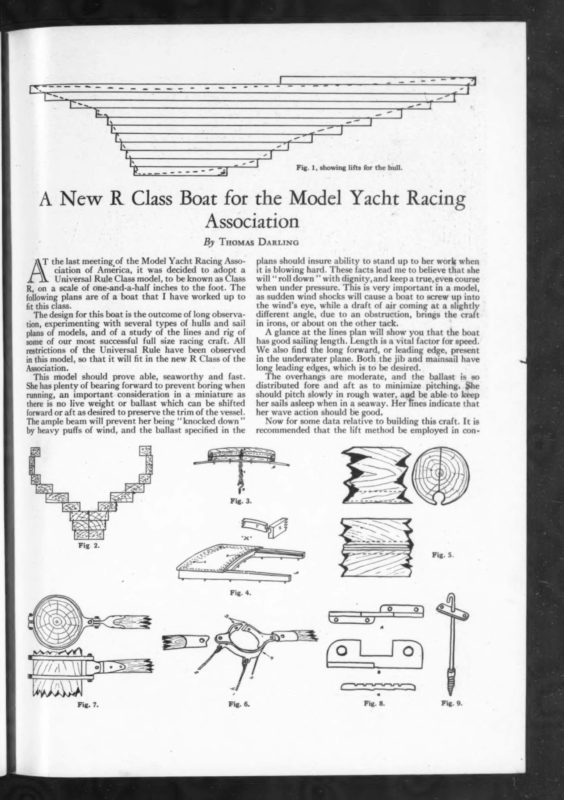
a Is, A New R aaa a | Fig. 1, showing lifts for the hull. Class Boat for the Model Yacht Racing Association By Tuomas Daruinc \ the last meeting of the Model Yacht Racing Association of America, it was decided to adopt a Universal Rule Class model, to be known as Class R, on a scale of one-and-a-half inches to the foot. The following plans are of a boat that I have worked up to fit this class. The design for this boat is the outcome of long observa- tion, experimenting with several types of hulls and sail plans of models, and of a study of the lines and rig of some of our most successful full size racing craft. All restrictions of the Universal Rule have been observed in this model, so that it will fit in the new R Class of the Association. This model should prove able, seaworthy and fast. She has plenty of bearing forward to prevent boring when running, an important consideration in a miniature as there is no live weight or ballast which can be shifted forward or aft as desired to preserve the trim of the vessel. The ample beam will prevent her being ‘‘ knocked down” by heavy puffs of wind, and the ballast specified in the plans should insure ability to stand up to her work when it is blowing hard. These facts lead me to believe that she will ‘‘ roll down ”’ with dignity, and keep a true, even course when under pressure. This is very important in a model, as sudden wind shocks will cause a boat to screw up into the wind’s eye, while a draft of air coming at a slightly different angle, due to an obstruction, brings the craft in irons, or about on the other tack. A glance at the lines plan will show you that the boat has good sailing length. Length is a vital factor for speed. We also find the long forward, or leading edge, present in the underwater plane. Both the jib and mainsail have long leading edges, which is to be desired. The overhangs are moderate, and the ballast is so distributed fore and aft as to minimize pitching. She should pitch slowly in rough water, and be able. to keep her sails asleep when in a seaway. Her fines indicate that her wave action should be good. Now for some data relative to building this craft. It is recommended that the lift method be employed in con- wie ee = > = So Sr ate (9 = Lo oO] al Fig. 5 Q) a I)
YACHTING ae WA NZ -~ I] iu L / March, 1926 .” Steteam. 86 NIT] | Y Sail plan of Class R model yacht, Model Yacht Racing Association of America. / | | i LL La vere KY { | \ scores ae The lines of a model racing boat to rate in Class R on a scale of 14 inches to the foot. Length o. a., 55”, w. 1. 37.5”, beam w. 1. 11.62”, draft 7.75”, rating 30.78. structing the hull. Reference to Figure 1 will give an idea of the appearance of the lifts when laid up. They are 1 inch in thickness, and should be cut from thoroughly seasoned white pine stock. The shapes for each lift can be obtained from the waterlines in the plans. Cut each half of the lift separately and join them in the center. This will give you a center-line, when assembled, which cannot be erased. The termination of each lift fore and aft will give you the outline of the keel, rudder post, etc. Mark the location of the stations while the lifts are in the square state, before saw cutting. Locate the forward and after ends of the lead before starting to shape the keel. Figure 2 shows how each lift appears after it has been sawed, if seen in section. The width of each lift is determined by plotting at the several stations, as shown. This sketch represents station 9. Be cautious and do not hollow too low down as some solid stock must be left for deadwood. The lead keel will be bolted to this deadwood. Figure 2 shows the relative thickness of the skin at deadwood, bilges, and sheer. The minimum thickness is 4”. Simply work the corners off each lift and the outside shape of the hull will be formed. After the inside corners of each lift are removed the hull should weigh about three and one-quarter pounds. When the deck beams and deck are fitted it should weigh about four pounds. Work the deck down to 14” in thickness. The deck beams are to be fitted at the point where headstay passes through deck, at mast, between mast and rudder head, and at rudder head. Make them 14” thick, and 1” wide. Camber 34” in 12”. The keel bolts are located at stations 8, 9, 10, 11, 12. A handle may be provided for carrying the boat by secur- & ~ : : = : & E
VYACHTIAG March, 192¢ Nautical Nuggets (Continued from page 66) now lo The law of averages is immutable. Dental statistics prove that fourout of every five over and thousands younger, too—are marred by Pyorrhea. Do you want to escape? It takes healthy gums to keep healthy teeth Bleeding gums are Nature’s first warning. Then the gums begin to recede, lose that rich, healthy pink color. Poisons collect in pus pockets and. often drain through the entire system, causing indigestion, anaemia, rheumatism and other serious diseases of mid-life. Take no chances—use Forhan’s If used in time and used consistent- ly, Forhan’s will prevent Pyorrhea, or check its progress — something ordinary tooth pastes are powerless to do. It contains just the right proportion of Forhan’s Astringent (as used by the dental profession in the treatment of Pyorrhea). It is safe, eficient and pleasant-tasting. Even if you don’t care to discontinue your favorite dentifrice, at least start using Forhan’sonceaday. Forhan’s.is more than a tooth paste; it checks Pyorrhea. Thousands have found it beneficial for years. For your own sake ask for Forhan’s Forthe Gums. All druggists, 35¢ and 6oc intubes. Formula of R. J. Forhan, D. D. S. Forhan Company, New York rhar FOR THE GUMS More than a tooth it checks Pyorr _ Just as a ship needs the closest attention under the water-line, so do your teeth un- sure to belay all lines carefully. Brac: the bow if keel is hung far aft. As the tide goes out you can use your sapolio and scrubbing brush from a dinghy on the off side, and by removing your shoes and stockings or wearing rubber boots, you cai scrub the inner side. Many yachtsmen would like t paint their craft in distinctive colo combinations. This is a laudable idea and one to be encouraged, but for heaven’s sake let an expert handler of oils and dryers mix it for you. Whit« and black have been the standard topside colors for many years. A few other colors have been used successfully, notably yellow, gray, and green. Blue is a hard color to use, and does not wear well outdoors. Light green is the most popular color for racing bottoms, but there are browns, reds, a white, and a bronze finish to be had. The use of a boot-top or line of some width, between the color on bottom and the sides, often makes for beauty and accentuates the water line. This stripe is different in color from either bottom or sides. With a bright or varnish topside finish, and a light green bottom paint, one can use a pure white boot-top line. Where a bronze bottom paint is used they often put on a green stripe. Yellow or buff, in various shades, seems to be the favorite deck paint. Battleship gray is used quite often and makes a pleasing combination when the sides are black and bottom green, white or bronze. In the next article will be found instructions relative to fitting out for a racing season. It will contain hints on overhauling your sails, renewing rigging, and placing of leads and cleats for the speedy handling of sails in racing. Building a Model R. Yacht (Continued from page 88) In figure 7 is shown a gooseneck. The mastbands are made of flat stock, and the cup or bell of tubing, pressed together where it enters the swivel. The swivel is made of stock which is oblong in section. All parts are bolted together as shown in the sketch. The maststep, shown in views “A” and “B,” Figure 8 may be fitted on deck. If the builder wishes to allow the mast to pass through the deck, and have an adjustable step the one in sketch “‘C”’ can be utilized. Center of effort can be readily shifted with this device. A hook for the headstay is shown in Figure 9. The shank is sweated