- “Trick” Designing of Model Yachts. Percy Tatchell. My excuse in offering the designed lines of my 10-metre International Rule model Sahara for publication is that they reveal a trick method of designing a boat.

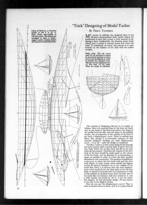
$F omen “Trick” Designing of Model Yachts By Percy TATCHELL Lines of Sahara, a 10-metre model, to the I Y. R. U. Rule. Scale, one-twelfth of M* excuse in offering the designed lines of my 10-metre International Rule model Sahara for publication is that they reveal a trick method of designing a boat. Incidentally, the drawing shows fairly HITE om sem clearly how a model is steered across and down the wind. To windward, of course, the custom is to steer entirely on the balance of the sails with the rudder WEICHT OF BULB 10$L8S WEIGHT OF ALUMINIUM FN LBS l; on as 1246″ i DISPLACEMENT es on. 15h LOS rigged model running before thewind on the starboard jibe. SAIL AREA ALLOWED os ann 15267 full size yacht. The sheets are arranged to steer a cutter- straight. Body plan. The set curve used for all sections is ticked in on several sections to show how it moves slightly in order i Py ele , 6 /\3 }%) \ \ | _ The set curves employed are: (1) For hull; (2) for bulb, They are made of celluloid. #0 *.0°9 scot COMES OF TH 1S QRAWING carer O..08 “6.4 auo0e 93 oaa” Coee, LevEs SULLBCay OL OOTS.wEr CCWEGUE!.W 91 ABB EY ROAD CHERTSEY Ma s raring) 2.80 Se ae.a tS eSSe LINES OF THE BB: 10 METRE OLD….cLASS TEN METRE RATING TO THE YACHT RACING RULE ont of ent > 8 OLGICNED OV PERCY Tatewey, to enclose the requisite area. ie r\ ¥ | \ The method of designing referred to is roughly as follows: Once the essential lines of the boat are fixed, that is, the shape of the deck from above, the shape of the profile from the side, and the shape of the midship section, the arrangement of the volume of the boat is got from a displacement curve. There is nothing new about this, though it is extremely common to find amateur designers working out their displacement curve — if at all — after the design is completed. The idea, I take it, is that a boat being forced through the water pushes aside a certain bulk of water with her fore body which has to flow back and fill up the hole when she has passed. Therefore the volume of the after body of the boat should be made equal to the volume of the fore body, and be disposed in as harmonious a shape as possible in order to create the least possible disturbance and commotion. The question immediately crops up as to where the fore body ends and the after body begins; in other words, where should the biggest section be placed? Should it be in the middle of the water line, when it is obvious that the same displace- ment curve would do for the after body as for the fore body, or should it be farther aft? It is customary to talk of this position in decimal terms from the bow end of the water line; for instance, half way would be .5, and a little farther aft would be .55 or .6 (of the water line length). In this particular design .53 was chosen as the site of the biggest section. How do you get the displacement curve? That is what everyone wants to know, and it is a point skated °
January, 1929 73 Yochting over very gingerly in many articles on yacht designing, even if it is not actually ignored. Without going into the matter too deeply (skating already, you observe), the procedure advocated is as follows: A line representing the length of the water line is drawn, and from the point chosen, .53 from the bow end, a perpendicular is dropped. You have already drawn the midship section and measured its under water area with a cunning little instrument called a planimeter, which gives the figure in square inches without bother. Set off this figure of square inches in units of length along this perpendicular to any convenient scale. To make this quite clear, suppose that the half mid-section area reads eight square inches on the planimeter (it is only necessary to deal with half the boat) ; you may like, for convenience, to use a 34-inch scale and mark off your perpendicular at 6. Colin Archer’s method of dealing with this perpendicular, supposing it is intended to make the after displacement curve conform to a trochoid, is given in Dixon Kemp’s Yacht Architecture. (The subject of designing to a displacement curve is fully dealt with in Norman Skene’s Elements of Yacht Design published by YACHTING.) Having marked this spot on the perpendicular and having decided to make the forward displacement a curve of versed sines, this curve is drawn by dividing the forward part of the water line into equal divisions, and erecting offsets proportional to the length of the perpendicular, as prescribed for that par- ticular curve. As this description is meant to be intelligible to novices as well as high-brows, it is well to emphasize that there is no difficulty in using a planimeter, and that a curve of versed sines and a trochoid curve are quite simple to draw, the method for doing so being given in most books on yacht designing. Continuing with the fore body of the boat first, it will be your object to make the area of each section correspond with the number of square inches indicated by the length of the offset to the curve opposite the position of that section. How exactly this is done, I shall come to later. We now measure, with the planimeter, the area enclosed between the curve of versed sines, the perpendicular and the forward part of the water line, a bit at a time, and add it up. Our object next is to draw a displacement curve for the after body of such a shape as to enclose between itself, the perpendicular, and the after part of the water line, an area equal to that of the fore body we have just found. , A curve of versed sines on this shorter base line will obviously be too small, while the trochoid encloses too much (see design), but by averaging the offsets of these two curves and reducing them proportionately, a curve can be drawn — by trial and error — that embraces the exact area required. We shall make the area of each section in the after part of the boat conform to the length of its corresponding offset, just as in the case of the bow half. A little reflection will make it evident that tables of areas for sections, with the midship sections in various positions in the water line length, could be drawn up, obviating the necessity for any displacement curve drawing at all. Now for the method of filling in the sections. It will be near enough if we take two sections in the bow half and two in the stern half and make them the correct area; all the others will follow. The trick attached to this particular design now comes in. It will be noticed that the top half and the bottom half of the midship section, ¢.e., that part of the curve above and that below the turn of the bilge (or greatest bulge), are drawn with the same drawing curve reversed, and that at the point where the two halves meet a spot has been inked on the curve. The curve used is one of a home-made set. I described a method of making these in the British Yachting Monthly for December, 1919, but an ordinary shop curve of the right shape will do as well, and it is not essential to use the same curve top and bottom. To put in the intermediate sections. On the body plan, or plan that contains the midship section, we have drawn a diagonal line and we mean to have the top and bottom half of the section meet always on this line, the curve above to be similar to the curve below, reversed. In other words, the greatest bulge of each section will be at the crossing of this diagonal, and the sections throughout will be drawn by use of a part of the same celluloid curve. Take the third section from the bow end of the water line. (See body plan.) Reference to the length of its offset on the displacement curve will show that it ought to have an area of X inches. The spot for this section at the deck we know from the other plans, and also that for the profile on the middle line. What we do not know and have to find — by trial and error — is the spot on the diagonal on the body plan where the upper half and lower half, drawn with a part of this same drawing curve, will flow sweetly into each other and embrace the required area. It is surprising how quickly this pleasant little puzzle solves itself, with a good piece of India rubber, the drawing in of light pencil lines, and marking where the ink spot has moved to, then testing with the planimeter. It will be noticed that the ink spot is equidistant from the diagonal top and bottom in each section, and that in the bow half, where the boat flattens, it crosses the diagonal, and that in the after half, where the boat becomes more bulgy, it recedes. Having got in two intermediate sections in the bow and two in the stern by this method, there will be five points through which to lay off the actual curve of the diagonal. This line will give the position of all the spots for the remaining sections on the diagonal in the body plan, and the rest of the boat can be quickly filled in, (Continued on page 108) (Left) International Class A model sloop Bunny Ii, designed by J. A. Potter. The plans of this model appeared in Yachting, August, 1927. Yankee (right), Doodle an Inter- national Class A model designed by S. Houghton Cox and built by E. A. Bull, which raced in the eliminations at Washington last July. She did well in light airs.
¥ 108 } ti January, 1929 mpeg “Trick” Designing of Model Yachts (Continued from page 73) all (except, perhaps, the extreme ends) with the same drawing curve. The celluloid curve used is ticked in on one or two sections in order that the process may be most easily followed. The bulb is developed in the same way, and has a similar displacement curve to the hull. So much for the method. What of the finished product? Frankly, the model Sahara’s deck line is too narrow forward; she needs at least another half inch flare on either side at her bow section. When drawing a deck plan one is apt to overlook the fact that the deck forward, owing to the sheer, is farther from the water than aft and should, consequently, be well flared. Her bulb was eventually moved back an inch — an easy job in a model — and a good deal of her aluminum fin cut away forward. In this trim the model has picked up quite a fair number of prizes, which after all is the acid test. A sister model rigged as Three and Sixpence — a close inspection of this sail plan will reveal the subtlety of the name — was quite a satisfactory performer, though it is impossible to keep the long unsupported luffs of the jibs up to the wind in a breeze. Yacht Alcyone, designed by Tams & King Increased | Comfort Reliability Living Space For this very reason I should expect to hear that the American staysail schooner rig is a qualified success in a strong wind. Most literature on yacht designing is very disappointing, conveying the impression that yacht designers are pure artists, that they conceive the type of boat they want and simply fair it up, whereas we know that “tips” abound. “‘ Drawing Office Tips’’ — there’s a fascinating subject. Who will write upon it? It is unreasonable to expect professionals to divulge their methods on which, to an extent, their livelihood depends, for the benefit of their rivals, though it is an adage that there is little to be feared from one who merely copies. Will not skilled amateurs hand over their “tips” for the information of all? Winter days are dull days, and a drawing board is a great standby. Let me offer the novitiate in designing some advice if he proposes to draw a boat. First, to check his principal dimensions from some successful boat; and, second, if he has much spare time to try out his ideas with models. IESEL ELECTRIC drive insures cleanliness and, through advan- tageous distribution of machinery weights, more space for living quarters and good “sea boats” in heavy weather. The multiple generating units of a Diesel electric installation also assure maximum operating reliability. Diesel Electric Yachts Equipped by Westinghouse Name Ay | ae i . Aux. Bark Aux. Schooner Aux. Schooner Valero ll Cruiser Cutty Sark 2 | | Type Aloha Guinevere icyone Elfay Aux. Schooner Aux. Schooner Owner Arthur Curtis James Edgar Palmer Henry W. Putnam Alexander Smith Capt. Allen Hancock Send for Special Publication 1776 describing Westinghouse Diesel electric installations in several famous yachts. Westinghouse Electric & Manufacturing Company East Pittsburgh 4 Pennsylvania Sales Offices in All Principal American Cities Service Seations in All Principal American Ports When the ‘mainsail split. The Six-Metre Wasp in a fresh breeze on Long Island Sound during the trial races last Spring.