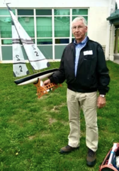
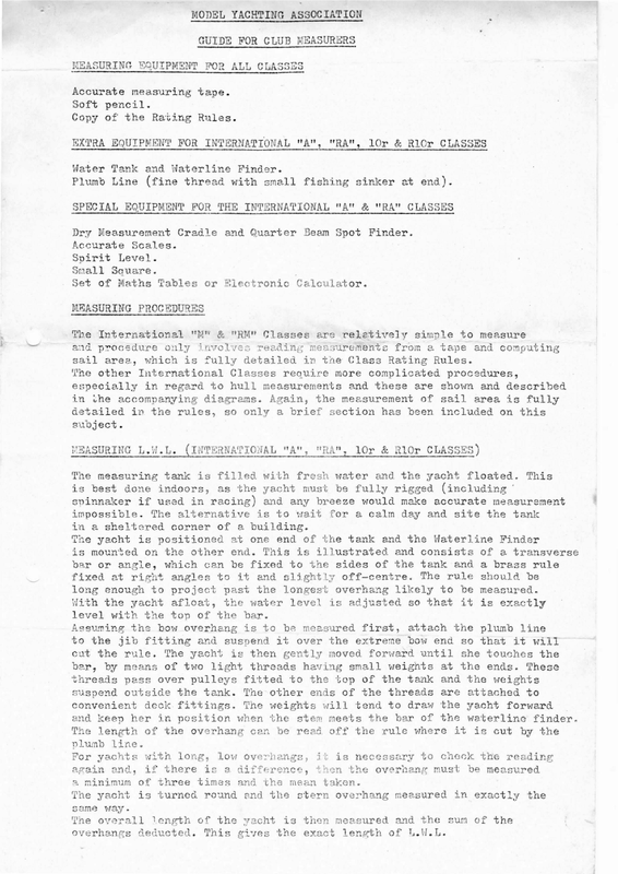
- Instructions for measuring a model yacht.

MODEL YACHTING ASSOCIATION GUIDE FOR CLUB MEASURERS MEASURING EQUIPMENT Accurate Soft FOR ALL CLASSE measuring tape. pencil. Copy of the Rating Rules. EXTRA EQUIPMENT FOR INTERNATIONAL “A”, “RA”, 1lOr & RLOr CLASSES Water Tank and Waterline Finder. Plumb Line (fine thread with small fishing sinker at end). SPECTAL EQUIPMENT FOR THE INTERNATIONAL “A” Dry Measurement Cradle Accurate Spirit Small Set and Quarter & “RA” Beam Spot CLASSES Finder. Scales. Level. Sauare. of Maths Tables or Hiectronic Calculator. MEASURING PROCEDURES The International 14 procedure sail The area, other the invelves which is fully International especially in “MY & “RM” only in Classes detailed Classes regard to hull in the rules, so reletively in the Class reauire more measurements accompanying diagrams. detailed are reading measurements Again, only simple to measure from a tape computing complicated procedures, and these are the measurement a brief and Rating Rules. of section has been shown sail and described area is fully included on this subject. WEASURING L.W.L. (INTERNATIONAL “A”, The measuring tank is filled with “RA”, 1lOr & R1Or CLASSES) fresh water and the yacht floated. This is best done indoors, as the yacht must be fully rigged (including ‘ spinnaker if used in racing) and any breeze would make accurate measurement impossible. The alternative is to wait for a calm day and site the tank ia a sheltered corner of a building. The yacht is positioned at one end of the tank and the Waterline Finder is mounted on the other end. This is illustrated and consists of a transverse var or anzle, which can be fixed to the sides of the tank and a brass rule fixed at right angles to it and slightly off-centre. long enough to project past With the yacht afloat, the water level level with the top of the the longest the cut jib fitting and the bar, rule. by means of two threads pass suspend outside the convenient The light tank. fittings. over the it is exactly threads attach the plumb extreme bow end then gently moved the The ends other top of the tank of the The weights will so that forward until having small weights fitted to overhang can threads tend to stem meets be read off the at the and the are of the rule where will she touches ends. it the These weights attached to draw the yacht the bar line it forward waterline is cut finder. by the line. For yachts with long, again be measured. adjusted so that be measured first, it in position when the length of the plumb is over pulleys deck. and keep her susnend The yacht is bar. Assuming the bow overhang is to to The rule should be overhang likely to and, 2 minimum if there of three is low overhangs, a difference, times and the mean it is necessary to then the check the reading overhang must be measured taken The yacht is turned round and the stern overkelng measured in exactly the same way. Tne overall overhangs tength of the vacht deducted. This gives is then measured and the the exact length of L.W.L. sum of the
-SAIL AREA MEASUREMENT Although this requirements is a simple procedure, of the individual close attention class rules. The should be paid to the following points should be carefully noted:- (a) The total rig, including the mast, is measured in the 10r & R10r Classes. (b) In the other classes, batten limits refer to the maximum permitted length of the battens, not the batten pockets, which may be any length. (c) Sail area measurement applies to triangular sails only. Any other type of rig is fully measured, permanently bent as are solid wing sails and rigs employing spars. (a) When recording alternative rigs on an “M” or “RM” Certificate, ensure that the suits clews of of sails concerned are jibs distinctly marked “A”, “B” or “C” in the and mainsails. (e) In the “A” & “RA” Classes, the fore triangle is measured, not the sail. Therefore, placed on the mainsail gooseneck be it set. set is deck important and mast measurement and on the Remember to to the owner’s and batten that at the the correct time marks main boom measure to on the mast at the the satisfaction. measurement of measurement. at clew, marks This the headboard, at beyond which the marks placed should be applies after the also to the sail must sails have Pay particular attention to roach not been limits spacing. (f) Take careful note of the individual rating rule renuirements in regard to the is a common number source of all measurements. hull of decimal of places error to and, be of recorded course, on Certificates. applies also This to the recording DISPLACEMENT In the must case of the be is the accurate. only really are too the inaccurate weight to measurement, give “A” & “RA” “D” “D” the satisfactory apparatus to use. as, the in in time, cubic centimetres. redio, including batteries – i.e. will sails, probably be Check that is not everything has INTHRNATIONAL “A” & “RA” the Dry Measurement and the other extreme dimensions, Bach end has height The Cradle Correct not best of the been unless, and weight to as This cross bars of if used and vane to lay the rig along the cannot take be the the and Beams allow for in its gear or deck, as is waterline of between 9 and a maximum draught if the yachts. built in is transferred one fixed length. end Allow for inches. construction obtained heaviest unit 70 the yacht a framework with which is used for taking Beam L.W.L. should measurements, any possiblie between 40 be very robust course, boom is basically allow for Allow for enough to be recorded complete with mast, included. Cradle. such measurements strong if using metric in full racing trim. as for measuring L.W.L. convenient a cross bar fitted, must or, Convert CLASS HULL MHASUREMENTS adjustable, Beam measurements. must 27.7 “tired”. critical. After taking the L.W.L. to and become in kilograms multiplied by 1000 to including spinnaker and found more equipment Spring or bathroom scales stretch multiplying by Weight top It springs inches by spars, position of the yachts require weighing and this a beam balance with the necessary weights conversion is the weight in cubic suit Classes, For this purpose, and Cradle Glued steel. 20 of and Quarter inches. ebout extremely is and The 14 inches. accurate. inaccurately made screwed joints are or
POSITIONING THE YACHT The movable distance ON THE CRADLE | end of the between ends Cradle check this dimension The Cradle should then be level. THIS Provide IS so and aft thread and exact that L.W.L. base as other measurements up absolutely frame until the found in the tank. level depend on its Double accuracy. and tested with a spirit ends. The yacht is on to L.W.L. easily for distort. lifted off the the Cradle in order to take the weight remains ends Do not, in the however, Cradle chock the of the Cradle. and ensure endings.- Check this at some time that the ends are at the exact the bow overhang by using the sinker. so distance the Cradle Ensure also L.WeL. BEAM is that that either end, the thread cuts the of the forward each fixed rule As can be on the Cradle seen, it is is exactly of the yacht hull sides, the central on the Cradle. and adjusting them ends are each so that, equidistant when the from the centreline (i.e. the threads are parallel). The distance between the threads The exact centre thread level at important stretching two thin threads between the cross bars at side touch the overhang. exactly level. the yacht This is obtained by threads set along the or chocks under the keel it Adjust the yacht the so many could quite high that Lower the yacht fore as off the and a heavy boat boat slid exact IMPORTANT. some wedges of the yacht is equals the of the (i.e. L.W.L. ’ is measured length and this is the should be marked on L.W.L. the hull Beam. at L.W.L.). This is for taking freeboard measurements. FREEBOARD Freeboard measurements Fore and aft L.W.L. are taken endings and at three the points centre along the of the L.W.L. hull – where the hull has been marked. The distance measured between the rules to upper deal at side with each point of deck rounded is from the and hull. deck edges This and L.W.L. to the position is defined excessive junction tumble—home in ‘the and is the point where a 45° tangent to the horizontal plane makes contact with the hull. The rules include The three on the two other sides. perhaps diagrams vositions side This not are and, is quite to illustrate the method of taking measurements. measured and the mean taken. if there is a precaution level on the a variation, take in case the yacht Do a check measurement an average between the is not absolutely true or machine. QUARTER BEAM LENGTH From the L.W.L. Beam measurement, beam An item known This is as the a two-part sliding plate The calculate the auarter beam and the 1/10th dimensions. Q.B. metal fixed to sliding plate is Spot Finder device, the is used to as illustrated, side with sae adjusted so that teke the Q.B. measurements. with e base block and a oe screws. the stance . from the top to the exactly central on the Cradle. is exactly 1/10th L.W.L. Beam. The upper lee lower edges must also be parallel. On the The set square its edge Q.B. is it Finder Do the same by ends of the yacht measure the Q.B. positioned until Spot divide The two end bars, just and on the at other L.W.L. side is repeated at It will spot the aft L.W.L. written be and the hull. ending each side of centreline. The is Q.B. Spot distance A small Finder slid elong from this edge of the measured. of the huli, add the two results together and two. process the point touches the the calculated. is this must distance base L.W.L. ending. down, be the the found other end of the yacht that, at the fore ending and, at the aft Therefore, to calculate the forward measurement end end, 9.B. subtracted and the Q.B. of the yacht, the point Length, and the aft Lensth the is also the @.B. aft L.W.L. of is measurement added.
Se = weaee sa SS ev Tt”. ony ee ee al an at eae a ae ee eS a ee a 7 a ar a er ae NS ae. =, rete eRe >= aa” been marked. The distance measured at each point is from the L.W.L. between the upper side of deck and hull. to the junction This position is defined in the rules to deal with rounced deck edges and excessive tumble—home and is the point where a 45° tangent to the horizontal plane makes contact with the hull. The rules include diegrams to illustrate the method of taking measurements. The three positions are measured and the mean taken. Do a check measurement on the other side two sides. and, if there is a variation, take an average between the This is a precaution in case the yacht perhaps not guite is not absolutely true or level on the machine. QUARTER BEAM LENGTH From the L.W.L. Beam measurement, calculate the quarter beam and the 1/10th beam dimensions. An item known as the Q.B. This is a two-part sliding plate The metal fixed to sliding plate is Spot Finder is used to take the 9.B. device, the as illustrated, with a base measurements. block and a side with adjusting screws. adjusted so that the distance from the top to the base is exactly 1/10th L.W.L. Beam. The upper and lower edges must also be parallel. On the The two end bars, set square its edge until 9.B. Spot Q.B. must it just touches the Finder and the same divide by on the L.W.L. be distance is positioned at this point Do the The ends of the yacht measure the exactly central on the Cradle. each side and the Q.B. hull. The distance from this edge of the add the two results together and is repeated at It will be found that, at the fore spot the L.W.L. ending and, at the aft aft L.W.L. small two. process the A Finder slid along ending is measured. other side of the huli, calculated. is of centreline. Spot ending. written down, the the Therefore, other to end of the yacht end, calculate the forward measurement Plus aft (3) Q.B. the point Length, subtracted and the Minus fore Q.B.L. and the Q.B. end of the yacht, 2.75″ 47.25″ 3.25″ 50.50″ aft Lensth the is also the 9.3. aft L.W.L. of is measurement added.
The calculations to determine now be carried out, if the yacht carries a Q.B. penalty can as detailed in the rule book. DRAUGHT The final straight measurement piece the keel. one side until The of it chocks the Refer to the the be taken top will of is the using the be Place section of the keel. beams as the Measure obtain the for further explanation. pivot from the draught a Cradle under repositioned for this. Cradle the timber to illustrations draugnt. longitudinal bars of the probably have.to lowest edge on the Cradle across the timber upwards, touches the thread to to of timber Tilt point, L.W.L. measurement. REGISTRATION — ALL CLASSES (a) Particular attention is drawn to the General Rules governing Rating, Registration & Measurement Classes. It is important of both Free that they Sailing and Radio should be Controlled read in conjunction with the Rating Rules for each Class. : (b) Check and double check all calculations and ensure that Certificates are properly This will completed before make his job easier sending them to and save time, the Class trouble Registrar. and postage. (c) Ensure that Declaration Cards are completed correctly and, when submitting Certificates for re-registration, with as much helpful information as possible for the Registrar. (a) When registering a new yacht or re-registering a yacht with a change of name, always is duplication, submit which at least is not three alternative names in case there permitted. (e) If a yacht is to be registered as a unit of more than one Club, ensure that the Certificate and Declaration Card are countersigned to that effect by the Secretary of the other Club (or Clubs) concerned. The wording should be:— the “Ii certify that @epmwrenveseseenstewreeteeeeee#ete to ee e@e eee this yacht is also a unit of MiveGe” (f) Declaration Cards should be dated as the Certificates. (gz) Do not forget to enclose a stamped—addressed envelope for the return of Certificates. (h) Remember that if you are in doubt about a yacht complying with the rules, you should refer to the Class Registrar for his ruling or, if a decision, he will refer the matter to the M.Y.A. he is unable to give Council. The Model Yachting Association wishes to contained diagrams in this are guide reproduced acknowledge from the Australian M.Y.A. some of the and the information following with their kind permission. January, (4) 1978.
MODEL YACHTING ASSOCIATION L.W.L. TANK and MEASURING PROCEDURE Lizht weignted toread Plumod line waterline finder Rule FT ee to aliow plumb line to hang vertically Long oe Tank – enough to —_ allow for extrems\_ ms designs reinforced against | water say 600 mm pressures WATERLINE FIiuDaR – Waterlina rl A , Pravinzs not scale . Plumod lins Note:— Great Pulley | ete care oan » n : i should be taken in measuring length overall. This measurement must be taken parallel to the L.W.L. Tank |
MODEL YACHTING ASSOCTATION International “A” Class Dry Measurement Cradle 200 mm Variable 190 ma +——+4 wh p14 — adjustable end | l Bolt | A Slot x —— eran | = fF & 1000 ma 450 mm for bolt so 150 mm J | ‘ ! 4 sane LEVATION ——> H poe eg Z : ; 7 ae eet Se Liars ieee ree = ; = a 5 300 mm | eee — – : 500 mm soe Vey Si 3 r oir | | i —— — eoeenpte 909 5e-aSaP TREE ERNT ERPEEOSIRA Ere mp I + ee = | 7 PLAN 2000 mm Adjustable 6909 mm end Friction bolt 3 CCONSTAUCTICS DIAGRAM Rule for bow overhang Slots . Brace 3 soldered block 25x 100x mr to cr 0 to r — meta ‘3 Adjustable j— screws 3 mm by 25x 100 mm Metal block (6) Dravings not to scale
MODEL YACHTING ASSOCIATION Distance of model’s as found in the LWL tank Plumb line Bow overhang rule | ~ L a under : atta. ward O/H as measured in tank MMASURING CRADLE te csatreiing os, touch3s hul] at max. Li beam J, gz) 3 3 £ R “A” equals: fore— level with spirit level Thread parallel – on cradle Set cradle absolutely keel POSITIONING BOAT ON eas Adjust boat | finde ne ane Chocks A €4 r 7] beam L Equal ¥ 5 aN booed isb deam divided into & PINDING LHL BEAM AND QUARTIER BEAM BUTTOCK – aes LWL Ls – @3ual ~uztear ——— ee ay Freeboard ay: stations —= Fore, Mid and Aft ci LWL Board under’ keel tilted until it Measure touches to top DRAUGHT Drawings not to scale ‘Reposition chocks. keel. corner. AND FREEBOARD MEASUREMENTS parts beam to find buttocks
f » MODEL YACHTING ASSOCIATION International “A” Class Quarter Beam Measuring Quarter beam spot finder touches hull Dry measurement at intersection of cradle Quarter beam buttock and 1/10th. beam waterline. Diagram showing wuarter bean Guarter spot bea {3 spot finding. finder Quarter dean This distance minus _ € NY dimension Fixed end of cradle. sgasurement Toreward and pius aft proceedure the same at adjustabdle end. quarter spot beim finder Syuars Quarter set at beam dimension DIAGKAM OF HQUISMENT Baa KBaSUREMEWT Drawings (8) not to scale