The Model Yacht is a published three times a year by the US Vintage Model Yacht Group
- The American Model Yachting Collection (Mystic Seaport). by John Snow
- 2002 Vintage Traditional Watercraft Regatta Report. by Annie Michnowicz and Richard Rogers
- The Pirate Model Yacht and the Little Pirates program. by Scott Rohrer
- R/C for little Pirate. by Rod Carr
- The R Class. by Earl Boebert
- Bill Bithell Inducted into the AMYA Hall of Fame
- The Most Beautiful Model Yachting Book – – Ever. by Earl Boebert
- A Model Plank Built Schooner Yacht. by F.J. Camm (1940) – lines and instructions for 40-in schooner

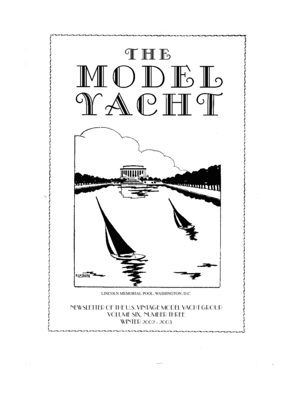
LINCOLN MEMORIAL POOL, WASHINGTON, D.C. NEWSLETTER OF THE U.S. VINTAGE MODEL YACHT GROUP VOLUME SIX, NUMBER THREE WINTER 2002 – 2003
NEWSLETTER OF THE U.S. VINTAGE MODEL YACHT GROUP VOLUME SIX, NUMBER THREE WINTER 2002 – 2003 Editor’s Welcome This marks the end of our sixth year of publication, and we couldn’t feel better about it. To commemorate this, we have a set of articles on the significant pond boat “Pirate” out of Seattle. We thank Scott Rohrer and Rod Carr for the material on this boat, and think you will find it interesting. For our technical supplement we have something a little out of the ordinary, a 40” LOA schooner designed by someone who was basically a model aircraft builder and who had some interesting ideas about how to construct a hull. We’ve added material on using modern materials and adhesives in case you would like to try your hand at this intermediate-level project. Just a reminder about our subscription policies. If you look on your mailing label you’ll see a two-digit number after your name. This is the Volume and Number of the last issue we think you’re entitled to. So if it says 63, that’s this issue (Volume 6 Number 3) and so it’s time to renew. We will also have stuck a renewal slip and a self-addressed envelope inside your issue to make it as easy for you as we can. If you think we made a mistake, just let us know at the editorial address and we’ll correct it. And if you are up for renewal and are hesitating, we’ve already planned next issue’s technical supplement: a 24” LOA “sharpie” designed by William F. Crosby, designer of the famous “Snipe” Class. Earl Boebert Ebbs and Flows The President’s Message Vintage Membership – Annual membership $20 fee is for three issues of VMYG newsletter – “The Model Yacht”. US VMYG lifetime membership is $100. Members also have access to technical assistance and vintage model plans. Our “how to” book and video package on plank-on-frame construction is available separately. To subscribe to or renew our newsletter and services, please send $20 check (payable to US VMYG) or cash ($100 for life membership) to: John Snow, c/o US VMYG, 78 East Orchard Street, Marblehead, MA 01945. For inquiries, call me direct @781631-4203 or visit VMYG Web Page at: www.swcp.com/usvmyg R/C Vintage M” (VM) Group 2003 National VM regatta is September 20-21. It is being hosted by Detroit MYC and will have display/racing competitions for VM model designs 1930 to 1970. There will also be similar competitions for new category of vintage racing class models: 36-inch designs. For VM rating rules and registration, contact Charlie Roden, VM Coordinator, at 732-462-7483 and cer@monmouth.com Detroit MYC contact is Alan Suydam at 248-476-3017 and asuydam@peoplepc.com Traditional Sailing Craft/Scale Models Group 2003 national racing/display regatta for R/C traditional sailing/scale models is July 31August 1 at annual Model Yacht Regatta at Mystic Seaport Museum, CT. It will include scratch-built and kit schooner models, plus Page 1
other traditional sailing designs. Schooner rules are available from Harry Mote our Traditional Sailing Craft Coordinator at 609-6600100 and hjmote@msn.com I am also alternative VMYG contact person for this event at 781-631-4203 and jsnow@drc.com Vintage Etcetera 2003 Woods Hole Model Boat Show Fourth biennial WH Model Boat Show is on weekend of April 26-27 at Woods Hole, Cape Cod, MA. It will feature large, indoor AMYA-VMYG exhibit, with open class invitational MY regatta Saturday (AMYA) and J Class regatta Sunday (VMYG) at Eel Pond. I am contact person for exhibit and J Class racing. 2003 Mystic Model Yacht Regatta Annual Model Yacht Regatta, now sponsored by AMYA, is scheduled for Mystic Seaport July 30-August 3. VMYG will host national Traditional Sailing Craft/Scale Regatta during event Thursday, July 31 and Friday August 1. There will also be AMYA national championships for Wheeler and Star 45 classes, plus regional for J Class. these being from Houk MY collection at Mystic Seaport Library. One of these is an original 1899 racing sloop design from the 1902 Rudder magazine book – How to Build a Model Yacht. 2003 USA/UK Challenge Regatta San Francisco MYC will host British skippers in reciprocal free-sail challenge regatta at Spreckles Lake, Golden Gate Park May 24-25, 2003. This is result of UK hosting 2001 free-sail M Challenge races, except that 36-inch Restricted Class models will be sailed in 2003. Details will be made available through VMYG web site and newsletter. Smaller Vintage Models Given increasing interest in vintage model yacht designs smaller than the M Class, such as those constructed through WoodenBoat School model yacht building courses and the “Pirate” described in this issue, VMYG will include R/C versions of these models in 2003 national VM regatta. If this debut is successful, VMYG may then consider this design as basis for another model grouping having an appropriate set of rating rules. 2003 WoodenBoat School Courses Fifth consecutive year of model yacht building courses at WB School, Brooklin, ME will be taught this summer by Thom McLaughlin and Alan Suydam. American Model Yachting Collection The American Model Yachting Collection at the G.W. Blunt White Library and Collections Research Center at Mystic Seaport Museum, CT is fully established. It is comprised of two major components: archives for material/plans at Library and future collection of model yachts/artifacts at Research Center. This collection provides us with unique opportunity, as present caretakers, to preserve valued material and models from today and our past for future generations, and to help educate others on our wonderful sport. Model Yachting Design Plans Preservation VMYG is now involved in long-term project to have select, older MY design plans scanned into electronic format for preservation. David Kadonoff, VMYG member, has volunteered to lead this effort with end result being CDs for VMYG and Mystic Ships Plans Division that can provide hard copies of these plans. Initial effort is to scan notable MY designs from 1890s through 1940s, with majority of John Snow The American Model Yachting Collection Recognizing the role of the sport of model yachting has had in yachting history, Mystic Seaport: The Museum of America and the Sea, has now established the American Model Yachting Collection (AMYC). The goal is to help preserve models, artifacts and material relating to the history of model yachting for research and future generations through the AMYC. As such, there are two AMYC components: the model yachting archives at the Mystic Seaport Library and the model yacht collection at the Museum’s state-of-the-art Collections Research Center in Mystic, CT. To paraphrase the Museum’s Senior Curator, “Mystic Seaport Museum wants to be the source for information and inspiration in the US on the subject of model yachting.” The Museum is working closely with the American Model Yachting Association (AMYA) and its US Vintage Model Yacht Page 2
Group events or (VMYG) to periodic develop a colexhibitions. lection of US In addition, racing model models may yachts. The or may not AMYA was be loaned, at founded in the discre1970 as the tion of the national orgaCurator in nization overaccordance seeing radiowith control model Museum polyacht activiicy. Also, any ties. The US models subVMYG was sequently established in assessed as 1994 to pronot acceptmote the pres- Sails and a lighthouse — what more could you want? The Calvert Maritime able after ervation of their receipt Museum, setting for the 2002 Traditional Watercraft Regatta. older sailing by the Sea(All photographs by Dan Gresham) models and port will be their heritage. Thus, the AMYC model collecreturned to donor. tion is based on radio-control and free-sailed Model appraisals for tax purposes must be racing class boats from 1800s to present-day. done independently, as the Mystic Seaport The collecting effort is phased, with models would be considered an interested party in being grouped according to when they were any such transaction. Scheduling an sanctioned as a class or originally designed/ appraisal will be a donor responsibility. For built. The initial collection will focus on key details about donating models, film, photos, AMYA designs and older sailing models. The artifacts, material (books, periodicals, “wish list” of models wanted is available records, etc.) to the AMYC, please contact from the AMYA and US VMYG contacts either Jack Gregory, 781-784-7625 & below. Note that models will be considered jgg@ultranet.comor John Snow, 781-631-4203. for donation at any time, if they are judged John Snow significant in regards to the needs of the collection. The donation process is for a candidate model to be initially screened by AMYAVMYG, with a thorough review of the supporting documents/photos. The Mystic Seaport Curator will then review this material, 2002 Vintage Traditional Watercraft along with the AMYA-VMYG recommendaRegatta tion, to decide upon the acceptance of a model or not. Subsequently, the AMYAA well attended, wonderful, windy, TradiVMYG will endorse the donor certificate of tional Watercraft Regatta, sponsored by US gift to the Seaport for the acquisition of a Vintage Model Yacht Group and hosted by model. Not all models proposed for donation Solomons Island Model Boat Club and Great will be accepted. This may occur when a Schooner Model Society was held on Septemmodel does not fit within the scope of the colber 27 to 29, 2002. lection, a design example already exists, or a Friday model is incomplete or damaged. Note that Mystic Seaport cannot accept models The Regatta got off to a fine start at 9:30 when donated with encumbrances or conditions, as registration opened in the lobby of the Calthey become part of the Mystic Seaport colvert Marine Museum in Solomons, MD. lection. This means they might not necessarily be on public display except for special Page 3
Jose Medina, from Des Moines, Iowa, with an racing winds. After a 9 a.m. Captain’s meet8 foot Schooner was one of the first to register ing, the Vintage M Class began their racing. for his first regatta. By noon 13 of the Six captains signed on for a spirited race and expected 26 captains, with almost 50 model the Vintage M challenge began. These boats boats, had registered. They then toured the present a beautiful sight as they glide museum and spent time at a special exhibit through the water with a fair breeze. on model yachting set up by Jimmy Langley Meanwhile six static judges began their task and the Exhibits Department staff. of rating the schooners or hull fairness, finMeanwhile, Solomons Island Model Boat ish, construction details, sails & rigging, and Club (SIMBC) members were setting the of course impact on the eye. Due to the magbuoys to precise GPS positions. (Do you nificent craftsmanship, this was no easy task. believe this?) A special thanks to Dave Butler, Mark Hughes, Carroll Lusby, Don Remers, Jim Friday afternoon some captains were interWeller, and Jonathan Wright for being our ested in rounding the marks and fine tuning judges. These individuals, most from the their rigging for the upcoming races. This Solomons area, are noted for their wood practice was extremely beneficial since the working and modeling skills. wind was consistently out of the east-northeast all Next on line weekend were the Skipjacks, the largEarly Friday est class of evening the entries with group seventeen enjoyed a models regiswine and tered. Thircheese gathteen of the ering held Skipjacks raced under the in some or all Small Craft of the five Shed, a perSkipjack races. fect haven for model The close proxboats since imity of the that’s where boats brought the on occasional museum’s collisions and traditional tie-ups requirSchooners at the mark. watercraft ing the use of are restored. the chase boat. The oyster shells and wood shavings on the With the acceptable confusion due to the floor, with plenty of tools lying about, added number of boats, the starts were clean. The realism to this regatta. Richard Rogers downwind legs for the Skipjacks are espesounded a homemade cannon loaded with cially demanding. The large mains take conblack powder, rammed hard with cotton and trol and the skipper must be alert and ready. a firing cap, thus officially starting the festiviSchooners, 50″ or less, also contended with ties. Friday provided a fine time for greeting the wind and the tight sailing quarters espenew and old friends while watching the suncially when rounding the mark! However, set and anticipating the next day’s races. our sailors were so good, we did not hear one Models were entered in five classes: Vintage protest although one model was required to M, Schooners 50″ and under, Schooners over do a 360. Of the eleven entries in this class 50″, Skipjacks, and Open. nine were raced and judged. After enjoying a break and a bag lunch preSaturday pared by club members’ wives, four captains Saturday the skippers awoke to a glorious competed in two open class races. The September morning with blue skies and great Sharpie’s captain was a little hesitant to take Page 4
her out due to the high to cut, that Tom and winds and seas as she Sandy Younger prohas a large open cockvided. While most pit and no bilge were relaxing, Buck pumps. Thankfully the McClellan and George wind moderated and Surgent finalized racthings went smoothly ing/static results. for all captains. (Schooners were judged equally for Saturday afternoon static construction and brought additional racracing abilities). The ing activity. First up official results of the were the large schoo2002 US Vintage ners. During the Model Yacht Group Regatta, eight of the Traditional Watercraft nine schooners, which Regatta were given in were registered, particthe last issue of The ipated in four races. Model Yacht. The winds were blustery, but the schooners Final Thoughts were prepared and In reflection the regatta showed us a beautiful Skipjacks at (on top of?) the mark. was indeed a special race. If one squints event. There was ones eyes, one can almost see the sailors on quiet, focused concentration on the part of board these beautiful vessels of a bygone era. the captains as their boats glided over the Small schooners and Skipjacks had addiwater with beautifully set sails — and the tional racing time on Saturday afternoon. occasional collision, tie up, or loss of wind. The wives and significant others cheered the To accompany this silentitude spectators procaptains on throughout the day plus had vided lots of fun and loud cheering especially time for networking of their own. Sandy Go George Go! Perhaps this, plus all the Younger arranged for a group to be given a white sails, caused some captains to admit special behind the scene tour by Carin that at times they may have been sailing Stringer of the Estuarine Exhibit tanks, espesomeone else’s boat — one of the many joys of cially the sea horse exhibit. Comments were remote control racing! extremely positive and the guests felt very No one was left out of the USVMYG Tradispecial. tional Watercraft Regatta. Seaworthy Small Saturday events concluded with a grill your Ships, set up their pond near the Calvert own steak dinner at the Solomons Island Marine Museum Exhibit Hall where young Yacht Club. There were more than a few visitors (future model Skipjack, Schooner, comments about the men doing the grilling and Vintage M captains) were able to build while the women provided coaching! The and sail their own free sailing square riggers, evening was a great success — beautiful view Bermudas and two masted sharpies. These of Solomon’s harbor from the deck of the club working pond models looked and sailed complementing the networking and camaragreat! derie of participants. Special thanks to Calvert Marine Museum Sunday morning dawned clear and gorgeous staff for their help and guidance with this with lighter winds but still great for racing. event, Dan Gresham for the multitude of digThe Vintage M again started the day, folital photos he took, and Frank Pittelli for a lowed by the small Schooners and then the great regatta web site: www.pittelli.com/ large Schooners. schooner/events/2002/USVMYG After a full morning of sailing and networkAnnie Michnowicz & Richard Rogers ing, noontime found all enjoying a delicious barbecue lunch from Jethros, a local restaurant. Dessert was a sheet cake decorated with the regatta logo — almost too beautiful Page 5
The “Pirate” Model Yacht And The “Little Pirates” Program In 1927, Ted Geary designed a 39” model yacht based on the lines of his very successful R-class sloop “Pirate.” The object was to get schoolboys interested in woodworking and sailing. The program was sponsored by two Hearst newspapers, the Los Angeles Evening Herald and the Seattle Post Intelligencer. In 1927, regattas for the graceful little craft were organized in both cities. In 1929, 300 “Pirate” models competed in a regatta in Los Angeles’ Westlake (now Mac Arthur) Park. “Pirate”’s skipper Matt Walsh officiated at the California event while her designer, Geary, oversaw the racing at Seattle’s Green Lake. While negotiating the purchase of “Pirate”, the syndicate that brought her to Seattle received original plans for the model racer. Now that “Pirate” belongs to the Center for Wooden Boats (CWB), the model boat program has been revived in Seattle as a joint venture between CWB and Alternative School No. 1 (AS1). Principal Ron Snyder has committed to building the little craft as an annual activity, now in its fourth year. The program includes an annual regatta held in early June where the students compete in a series of races for the coveted Pirate Cup, a perpetual trophy donated by Seattle boatbuilder Norman C. Blanchard. On June 8, 2000, nine boats competed in a series of seven races. The series winner, and winner of the 2000 Pirate Cup, was Nevin Root and is boat the Arctic Fox. Since then, over thirty “Pirate”s have been built in Seattle, most by middle-schoolers. On June 10, 2003, the fourth annual Pirate Cup regatta will be held at the Center for Wooden boats on Seattle’s Lake Union. Ted Geary started designing pond racers for school kids in 1921. His first design was a 40” scow form sloop that was the basis for the formation of the Seattle Model Y. C. In 1922, he drew a 72” C-Class model based on his famous R-class racer Sir Tom. While Geary drew the hull, the rig was designed by Dr. Walter Many. Dr. Many’s own Arborita, won the National Championship in the class in 1925. Geary spent hundreds of hours teaching youngsters about sailing, design and boat building. After moving his practice from Seattle to Los Angeles in 1930, he designed the Six-Metre model racer Olympic after the emerging Six-Metre fleet that grew there as a result of the 1932 Olympic Games. Modern “Pirate”s in Seattle Doing a model boat program was not what the Pirate Syndicate had in mind when they began restoration of the 40-footer. Such a big job asks a lot of the volunteers who undertake it. Such projects, when undertaken by a museum like CWB, also require financial support, both private and public. Placing “Pirate” on the National Register of Historic Young skippers retrieve their boats. We need more programs like this and Dale Wenninger’s Mentoring Project. Page 6
Landmarks brought added support for the project. Grantors, however need more than just history to take an interest in such things. Most often, public interaction, including programs for kids, is what brings grantors and donors to contribute. Most heritage vessels spend time with kids singing chanteys, tying knots and boat riding to affect this. For us, to have an authentic, historical and creative kids program dropped into our laps was absolutely ideal for both the old boat and the Center that has a long history of cooperation with Seattle Public Schools. The Pirate Committee is comprised of seven active volunteers. Until the “Pirate” restoration is done, we are somewhat limited to working with just one school and one classroom. When the big boat is sailing, we expect to publish a manual and to promote the class to other interested schools and yacht club junior programs. The Boats Ever conscious of historical accuracy, we have made very few modifications to the original plan. These are straight-line, freesailors that balance well and sail like a shot. The healthy righting moment and configuration of the “cockpit” combine to withstand heavy gusts without taking any water over the side. Where Geary called out a cedar-planked deck, we have substituted luan door skin although some of our group have planked their boats’ decks with western red cedar. We have altered the rig only slightly by moving the jib boom attachment an inch back along the deck from the tack fitting. This “balanced” boom resists rising in a puff. Combined with an “un-vanged” main boom, pressure transfers forward in even a heavy puff keeping the little sailors on their straight line course. All of the rigging can be obtained at a kite shop and an Ace Hardware store. For the middle-schoolers who build and race little “Pirate”s, the completed boat represents the biggest, longest project any of them have ever undertaken. We begin in mid-October and, working once a week, complete the vessels by mid-May. While many adult modelers have fit the boats with R/C gear, it would add too much time and complication to our tight schedule with the kids. To the purist, this “revisionist history”, detracts from the wonderful historic aspect of the design, anyway. The Kids Some students want to, and can, build a boat solo. Others want to do it but need a little help to get it done in a single school year. Others just want to be involved in a minor way. To accommodate all of them, we set up in teams of 2 or 3 students. The kids designate a builder (“skipper”) and helper (crew). This gets more of the kids involved and makes for a good team when the racing comes along at the end of the year. Sixth and seventh graders are not fully developed and their hands tire quickly when driving a chisel or a gouge or a rasp. Much fun comes at the end of the year but before the races. Painting and naming the boats creates real excitement and gives the builders another creative outlet. At he regattas, we ask the kids to discuss their paint scheme and explain the name of the boat. At the 2000 regatta, one of our female modelers, Ms. Sarah Galvin, painted her boat all black except for multi-colored flames extending a third of the way back from the bow. She named the boat Sea Bunny. When she came to pick up her prize, I asked about the name and how it fit the color scheme. A seventh grader, she replied, “I was trying for an ironic effect”, and sat down. The Racing The courses are set up cross-wind to make for a reach over and a reach back. This constitutes one lap. The skipper starts the boat and the crew waits on the other side to turn the little racer with a long bamboo stick with a tennis ball on the end. Lately, the crews have taken to turning the boats with such speed and force that we have had to remove the rudders so that they don’t jam over to one side sending the models in circles. Any kid that builds a boat is eligible to race for the Pirate Cup until they graduate from High School. This has swelled the fleet to over twenty boats. We race in heats; eliminating down to the final six boats that race for the Cup. The 2002 Pirate Cup was won by Chris Green of Evergreen High School. Chris’ S. S. Elmo was one of the first fleet built and is still fast. Page 7
At the Pirate Cup prize giving, the Cup is awarded to the winner. In addition, two internships in boat restoration area warded to the model makers who show the most interest and aptitude. The kids work at the Center for Wooden Boats during the summer and are paid for their effort. This valuable extension of the program provides direction for the most inclined kids and adds a valuable dimension to the whole thing. This is sponsored, every year by the Women’s Group as Seattle Yacht Club. Perhaps the most poignant moment in this program took place at the 2001 Pirate Cup when Mr. John K. Bussey of Palos Verdes Estates, CA, presented the Cup to winners Emil Murphy and Carl Anderson. Now in his nineties, Mr. Bussey was the winner of the first regatta ever held for this class in 1927. Following his victory, young Bussey was taken on board “Pirate” by owner/ skipper Thomas S. Lee for a race in Los Angeles Harbor. Once “Pirate” is completed, we will continue this tradition with our modern-day modelers. Mr. Bussey’s boat, and the trophy she won, are on permanent display at the Los Angeles Maritime Museum at San Pedro, Marifrances Trivelli, curator. The Future We intend to build on the program until it is available to any kid in the country that wants to build and have one of these graceful craft. We will market plans, keels, rigs and sails as a small income stream to maintain the “Pirate” and encourage the craft of model making. With our the regular support of Seattle Yacht Club, Seattle Model Yacht Club, Fisheries Supply, Inc., and the designer’s daughter, Mrs. Sharon Gee, the future is rosy. The Past We continue to look for other areas where these boats were built and raced in the Twenties. Promoted by the Hearst Papers, they are rumored to have been built in Atlanta, New York, Washington, DC and Detroit. Anyone having knowledge of these fleets is asked to contact us via our web site, www.R-boat.org. Scott Rohrer R/C For The Little “Pirate” Design Objectives R/C “Pirate” was contemplated as an addition to the Center for Wooden Boats free-sailing “Pirate” fleet. It was hoped that a change from the original all wood bread-n-butter construction to a plank on frame approach would garner sufficient weight savings in the hull to allow for the addition of lightweight R/C gear. The large mainsail and small jib made a free sailed “Pirate” very difficult to sail on a run downwind, so most sailing of the original boats was done on close and broad reaches where the lack of a boom vang allowed the mainsail to lift in response to wind puffs to keep the boat on a straight course. Some of the original boats were apparently built with boomkins out the transom which extended the length of the boat enough to allow a traditional backstay to be fitted. Such an addition looked a bit “clunky”, so the traditional rigging plan was modified Rod’s radio version, showing the elegant lines of the and a pair of aft-leadboat. Page 8
ing lower shrouds were fitted to hold the mast up when running downwind. chosen made from a 2 oz. stabilized nylon that has proven successful in a large number of other R/C Construction boats where a Construction traditional was plank appearance and frame was desired above Wateralong with The framing of the R/C version. line 2B on the good perfordesign drawmance. The mainsail was mounted on a jacking, and solid wood below. The cast keel balline held to the after face of the mast by a row last was drilled and tapped to accept brass 1/ of cotter pins. The jib luff hem slid over the 4 x 20 bolts which were run down through jib stay. the solid wood and into the ballast prior to Sailing gluing up. The deadwood was then easily Sailing of the R/C version was planned for faired into the lead and a smooth form was only light airs, (up to 5 m.p.h.) in sheltered accomplished. water. Parks and urban ponds were the venFraming was 1/4” birch plywood with 1/8” ues planned for the free sailed boats, and that mahogany planking glued to the frames. The holds true for the R/C version too. inside of the framing was given a coat of West System epoxy and was sufficiently Epilogue strong to not require additional reinforceUnfortunately the R/C “Pirate” had a subment with fiberglass cloth, which would have stantial impact on everyone who saw her, added substantial weight. and it didn’t take long for a suitor to sweep The deck was 3/32” plywood, stained with her off her stand and carry her off to Texas. an aniline dye to a reddish orange that I favor Porter Loring is her new owner. for vintage appearance. Spars were sitka Rod Carr spruce and hardware was from A.J. Fisher1 who have now ceased operation and will be sorely missed. Radio Gear Installation R/C gear consisted of a tiny FMA Direct Quantum 8 Sub Micro receiver, NiMH batteries and Futaba rudder and sail servo. All gear, including the head of the rudder stock can be easily accessed through a generous deck hatch located aft of the mast and before the mainsheet exit guide. Sails The free sailed version uses single panel sails of a woven material. This makes for a fairly flat mainsail that works well in concert with the vangless rigging mentioned above. For the R/C version, fully paneled sails were 1. Bob Irwin is still making parts “on a hobby basis.” Contact by mail only, 1002 Etowah Ave., Royal Oak MI 48067. Catalog is $4.00. The R Class The R Class was established some time before WWI using the then-new “Universal Rule” for rating yachts. R boats are typically just under 40 feet in length and carry around 600 square feet of sail depending on the exact size of the boat as described below. Page 9
The lines of the “Pirate” pond boat designed by Ted Geary. The dotted lines show the approximate underwater profile of the full-size boat. Geary dropped the keel for stability and made the rudder vertical to simplify construction. Copies of Geary’s original full-size construction plans for the model are available for $20.00 from The Center for Wooden Boats, 1010 Valley St., Seattle WA 98109. Thomas Darling’s “20-Rater,” which is an R Class design to 1 inch equals one foot. In this boat Darling kept to the exact constraints of the rule, sacrificing draft and sail area in the process. Full size plans for this model are available for $20.00 from Vintage Plans, 9219 Flushing Meadows NE, Albuquerque NM 87111 Charles Mowrer’s “Ardelle,” a full-size design. The constraints of the Universal Rule encourage that “J Boat Look” of graceful overhangs. Elements of the Universal Rule, including the crucial Quarter Beam Length penalties, were incorporated in the rating rule for International A Class models. Page 10
Diagram illustration the notion of Quarter Beam Length. “B” is the maximum beam at the load water line. The artificial horizontal plane 1/10 B up was chosen to simplify measurement of boats on the water. The points where that plane intersect the vertical plane at B/4 from the centerline defines the Quarter Beam Length or “q.b.l.” The class population exploded in the 1920’s, with a large number of boats and intense competition centered in Marblehead. By 1928 there were also large fleets in Long Island, the Great Lakes, and up and down the Pacific coast. Besides Ted Geary, R boats were designed by Nathanael Herreshoff, L. Francis Herreshoff, Edson Schock (who was a model yachtsman), Frank Paine (who designed the J Boat “Yankee,”), Starling Burgess, John Alden, Charles Mower, J.W. Roue (who designed the schooner “Bluenose”) and Charles Nicholson (who designed the J Boat “Shamrock IV”). In 1928 a new R boat could be built for between $5,500 and $8,500 and used boats sold for three to four thousand dollars. The Universal Rule From the beginning of rating rules 1844 to the America’s Cup of today there has been a continual battle between the rule makers and the rule beaters. The rule makers attempt to devise a rule which encourages innovation but outlaws “freaks” — boats that are unsafe or just plain ugly. The rule beaters search for loopholes and exploitable factors to improve performance, even if a “freak” is produced. The rule makers then modify the rule, the rule beaters go back to work1. The Universal Rule was the product of several committees, and it would be foolish expect the result to exhibit either artistry or science. The various committees simply tinkered with the rule until it produced yachts of a form they liked, and then they had the sense to quit. 1.At the time of writing, the rule-beaters at the America’s Cup were using the clause permitting “appendages” to beat the clause forbidding hollows or reverse curves in a hull. And so it goes, even today. The rule is most commonly, and misleadingly, presented as the following formula: L × SA Rating = 0.18 × ——————-3 D Where: • Rating = The value used to determine the class of the boat, in actual or scale feet. To qualify for the R Class, this number must be below 20 feet. For the J Class, it must be between 65 and 76 feet. The closer a boat’s rating is to the upper limit of its class, the faster the boat can be expected to go. • 0.18 = A “fudge factor” included to make the boats rated under old rules maintain the same approximate rating under the new rule. • L = “Length,” to be defined later. • SA = Sail Area, in square feet. • D = Displacement, in cubic feet. Herreshoff’s definition of “Length” addressed the “rule beater” technique of long flat “scow” hulls whose load waterline (on which earlier rules were based) was much shorter than the “sailing length” presented to the water when the boat was heeled. Herreshoff asserted that the true “sailing length” of a heeled boat was to be found at a buttock, or vertical slice, of the hull halfway between the centerline and maximum waterline beam of the boat. This dimension eventually became the so-called “Quarter Beam Length” as shown in the diagram, and its relation to any real or imagined “sailing length” was long forgotten. Page 11
A second innovation in the rule was the notion of “penalties.” Rather than introduce fixed limits on dimensions, the rule allowed designers to exceed the limits at a cost in sail area. After sixteen years of experience and “tuning” of the rule, the result was described by Charles Poor his Men Against the Rule (1937): … the Measurement Rule became a single-factor (sail area) rule with limits and penalties for departures from what was deemed a wholesome, seaworthy type of yacht. The rating, or measurement for racing purposes, became a direct percentage of the square root of the sail-area; such percentage being determined by a sliding scale depending upon water-line length. To control undesirable features of design three limits were imposed upon the design of the hull, with severe penalties for infringement beyond these limits. These hull controls are: There exist published plans for both one inch and one and one half inch models by Thomas Darling and Walter Maney. In all of these the “normal” displacement number (a function of the waterline length) was used in calculating the rating rather than the lighter, actual displacement1. This was possibly done to simplify the measurement of the boat. Darling’s smaller boat, called by him a “20-rater” rather than an R Class model, was published by the Stanley Works as part of their series of home workshop plans and also published in Model Craftsman magazine. Many boats were made, and plans are still available from the USVMYG. The table below gives the “design space” for a typical one inch to the foot design, and shows how the rule forces the designer to choose between the various factors that contribute to or detract from speed. 1. Limitation on Draft: The draft of all yachts is lim- R Class Limits for Models of One Inch Equals One Foot ited by a sliding scale depending upon water-line length; heavy penalties are imposed for excess draft. 2. Limitation on Quarter-Beam: The quarter-beam length is limited to a percentage of the water-line length determined by a sliding scale varying with water-line; heavy penalties are imposed for excessive quarter-beam length. 3. Limitation on Displacement: The normal displacement of a yacht is determined by a sliding scale depending upon water-line length: heavy penalties are imposed for “lack” of sufficient displacement: no premium is given for excess displacement. Except for these three limitations the designer is perfectly free. The type of yacht produced by the new rule is seaworthy, wholesome, with relatively small rig, good living quarters, and easily handled. R Class Models Thomas Moore’s 1928 book Build a Winning Model Yacht makes passing reference to a “Universal Rule for Models,” about which we know almost nothing. We do know that R Class models were built at scales of both one inch and one and one half inches to the foot. A one inch to the foot model is close to a 36/ 600 and the larger boats were about the size of an M Class. Sail Area LWL Max QBL Max Draft Max Mast Ht 575 sq. in. 31.6 29.8 6.8 45.8 580 sq. in 29.8 28.2 6.5 45.9 590 sq. in. 26.8 25.5 6.0 46.3 600 sq. in. 24.4 23.4 5.7 46.6 610 sq. in. 22.4 21.4 5.3 47.0 620 sq. in. 20.7 19.8 5.0 47.3 625 sq. in. 20.0 19.1 4.95 47.5 Thomas Darling’s design is precisely in the middle of the range. “Pirate” and the Rating Rule The basic dimensions of the “Pirate” model are as follows: LOA: 39 inches. LWL: 24.3 inches. QBL: 23.1 inches. Draft: 7.5 inches Sail Area: 667 square inches. Displacement: 160.2 cubic inches. Page 12 1.This point confused us when we presented the calculation of the rating for Darling’s boat in our Volume Two, Number Three issue.
These dimensions clearly exceed that of a scale R Class boat to one inch equals a foot, yielding a rating of closer to 21 inches. This is not surprising since “Pirate” was intended as a one-design boat — Ted Geary simply added draft and sail area for maximum performance, which by all accounts is lively. Earl Boebert the club and Euan is a professional photographer and master builder and restorer. The book they produced is more than a simple history; it is a fine art book whose topic is model yachting. Euan’s pictures are very special, so much so that I chose not to reproduce one here, as our low-resolution printing simply would not do them justice. Go to www.victoria-water.com and see for yourself. Bill Bithell Inducted Into AMYA Hall of Fame AMYA selected Bill Bithell, Swampscott MA, and VMYG Life Member, for its Hall of Fame in October 2002. As he did in his early race career, 1932 to 1950’s, Bill set another precedent for model yachtsmen: he is the first person to be selected for his accomplishments to our sport prior to the 1970 establishment of the AMYA. Bill turned 92 just after his Hall of Fame notification by AMYA President Dick Rutledge, and is truly deserving of this honor. We thank VMYG member Charley Williamson for Bill’s original Hall of Fame nomination and for documenting his noteworthy career as a builder, racer, mentor, and supplier to model yachtsmen as an expert sailmaker and fittings specialist. John Snow There are only a small number of copies available, all signed and numbered, so don’t waste any time! Cost is $NZ150 including shipping anywhere in the world, or about $75 U.S. This may seem a lot, but not when you see how special this book is. Can be ordered from the Web page given above, or by mail from: Euan Sarginson Photography Ltd. 40 Gilby St. Christchurch New Zealand In any case, make sure you peruse the Web page in depth. The picture of the A Class boat being followed by sharks is worth the price of the whole book. Earl Boebert The Most Beautiful Model Yachting Book –Ever. In 1998 we travelled down to New Zealand to participate in the 100th Anniversary celebration of the Christchurch Model Yacht Club, who sail on a beautiful lake called “Victoria Water” in the middle of Hagley Park, one of the loveliest urban parks in the world. At the time, the club members were planning a book to commemorate the event and the history of the club. It has been a while in coming, but well worth the wait. The two authors are Hugh Hobden and Euan Sarginson. Hugh is a long-time member of A Smaller Vintage Class This fall at the Detroit Regatta we will be experimenting with the idea of a smaller vintage class to complement the VM’s. There are several candidates available: Spring Lake is working on a smaller class, there is the Thomas Darling’s 20-Rater and “Starlet.” All these would fit in a 36/600 class. “Yankee III” Page 13
is a 36” LOA 450 sq. in boat and “Pirate” is 39” LOA. There are also numerous designs to the UK 36 in. Restricted rules which have more than 600 sq. in of sail. So we’ll have to be careful not to exclude any significant designs. Details are not final yet, but for the Detroit event if you show up with a boat under 50” and it looks “vintage,” you can count on being able to sail. If you have any comments or questions about this, please contact me at the editorial address. US Vintage Model Yacht Group (US VMYG) of the American Model Yachting Association. Charlie Roden Vane Gears Available Charles Blume has several M and A class size vanes available for sale. Contact him at ccblume@att.net or Box 227, Port Washington NY 11050 Earl Boebert Earl Boebert Bits of Oakum The Mentoring Project in New Jersey Progress Report Below is part of the original notice that went into the newspapers. The first class started in October with 10 kids. A second class will start in January with 7 kids. We have 17 adult mentors, 10 of which have or are in the process of building Madcap. Model Sailboat Mentoring Project A model sailboat mentoring project will be launched this Fall at the Court Street School Education Community Center, Inc. in Freehold. The project is open to all young persons in Monmouth County. It pairs an adult mentor with a boy or girl 12 years of age and over to build a radio controlled Marblehead class model sailboat. Each participant in the project will construct a 1937 design named Madcap, which is believed to be one of the more beautiful Marblehead designs. On completion, the boat will owned by the boy or girl and will be suitable for a lifetime of use. Participants will benefit from the life experience of setting and achieving goals. Specific skills to be acquired include project planning and scheduling, the proper and safe use of hand and small power tools, precise wood and metal working, basic boat design, an understanding of the principles of radio control and the principles and practice of sailing. The program was designed by Dale Wenninger of Swampscott, MA, a member of the The Model Yacht is published three times a year by the U.S. Vintage Model Yacht Group. Copyright 1998, 1999, 2000, 2001, 2002, 2003 U.S.V.M.Y.G. Reproduction for noncommercial purposes permitted; all other rights reserved. Editorial Address: 9219 Flushing Meadows NE Albuquerque NM 87111 Email: boebert@swcp.com Phone: 505 823 1046 Officers of the U.S. Vintage Model Yacht Group: President: John Snow Eastern Vice-President: Ben Martin Midwest Vice-President: Al Suydam Western Vice-President: Dominic Meo, III Southeastern Vice-President: Thom Mclaughlin Vintage M Class Coordinator: Charles Roden A Class Coordinator: Rod Carr U.K. Coordinator: Graham Reeves Canadian Representative: Doug McMain Historian: Earl Boebert Archivist: Jim Dolan Page 14
A Model Plank-Built Schooner Yacht Editor’s Note This chapter appeared in a rare, but otherwise unremarkable, book that appeared in wartime England. The author, F. J. Camm, was the editor of Practical Mechanics magazine, and the chapter is almost certainly a reprint of one or more magazine article that appeared before the war. Camm was principally a model aircraft builder and it shows in his somewhat unorthodox methods of construction. Nevertheless, this is an interesting “intermediate” boat in that it has about as simple a round-chine planked hull as one can make, has a very simple rig, and at 40” LOA is a tractable size. It would adapt well to radio control as a “windler,” or “fun boat.” The chapter is reprinted as it originally appeared, and an afterword is provided to suggest how modern materials may be used. The Schooner Yacht The construction of a model yacht with a planked hull is a long job, and the reader who intends to make such a model must be prepared to spend many evenings making the hull. Experience and skill are not so much required as care and patience, and a reader commencing this model now will have an interesting occupation during the coming months, and a fine model when the spring arrives. reputation for not sailing well, but this model, being designed as a schooner from the start, instead of merely rigging a cutter hull with two masts, puts up a very good performance and has surprised several experts by its ability to sail close up to the wind. Full-Size Drawings The first thing to be done is to make a full-size drawing. The model is 40 in. long on the deck by 9 in. beam, and has displacement (i.e. total weight of model), 9 1/2 lb., but if all dimensions are reduced in proportion a smaller model should give satisfactory results2. Make a full-size drawing of the hull shown in Fig. 58 as accurately as possible3; the vertical lines are 4 in. apart and the dimensions given are above and below the water line. Put the water line on all drawings, and mark it on every part made, as it is the datum line from which the measurements are taken. Also number the vertical lines from 1 to 9; these represent the positions at which the sections are made. Having drawn in the profile, the shape of all the separate pieces forming the layer of the composite keel should be drawn as shown in Fig. 59; the notches and tongues are to ensure a watertight joint. The shapes should now be traced down to 1/4 in. mahogany and cut out with a fretsaw, taking care that the grain runs as indicated. The five pieces should then be laid out on the full-size drawing, to check their shape when assembled, and altered if inaccurate. These five pieces are held together by other pieces fitted on each The described below has been specially designed so that fretwood1 may be used throughout, except for the spars. A schooner was decided upon as looking nicer in the water than the more usual “Bermuda” rigged boats. Schooners sometimes have a 2.It probably would not be wise to reduce the size below 36 in. LOA. — Ed. 3.The figures are reproduced here 1/5 size to simplify enlargement by photocopying. — Ed. 1.Thin sheet wood, suitable for cutting on a jigsaw (called a “fretsaw” in the U.K. and elsewhere). — Ed. Page 15
Page 16
side, sandwich fashion, as shown in the sectional view, Fig. 62. These side-pieces should be drawn in on the full-size drawing as indicated by dotted lines in Fig. 59, then traced onto 1/4 in. mahogany and cut out. The grain should be along the longest direction of each piece in this case, the joint between each piece being of a the simple “step” type. On one side layer the joints come between sections 1 and 2, also 5 and 6, but on the other side make the joints between sections 2 and 3, also 7 and 8. The are indicated in Fig. 59 and they can also be seen in the photograph Fig. 64. The profile of the side layers is 1/8 in. smaller along the bottom, increasing to 1/2 in. at the bow, to allow for the thickness of the planks, the allowance being greater at the bow because the bow because the planks approach the keel at an acute angle. The Composite Keel Now varnish each of the eleven pieces all over with thin shellac varnish, which will dry very quickly. This varnish can be made by dissolving flake shellac in methylated spirits. The composite keel can now be permanently screwed together with countersunk brass screws 1/2 in. No. 3. Adjoining surfaces should be painted over with thick shellac varnish (about the consistency of cream), and screwed together while the varnish is wet. This forms a kind of glue not as strong as ordinary glue, but absolutely waterproof. Don’t use ordinary glue anywhere on the yacht, and avoid the use of a single piece of iron or steel. While assembling the hull the fin should be held together by a flat piece of wood, say 2 in. by 1/2 in., screwed temporarily on one side. This must not be stuck on with shellac, of course. The finished keel must be quite free from cockling or twist, or the hull will not be symmetrical. The ribs are the next item; a pair of these is required at each of the numbered sections. The contour of each rib is obtained from Fig. 66 and nine full-size complete sections of the hull should be drawn similar to Fig. 62. The dotted lines of Fig. 66 represent one inch square, so there should be no difficulty in transferring the shape correctly to the fullsize drawings.1 Note that Fig. 66 shows sections of the hull so the ribs must be smaller by 1/8 in. to allow for the thickness of the planking. This is very important and it is easy to make a mistake here. The thickness of the deck must also be taken into account. The deck is cambered on top, the centre being 3/16 higher than the edges at amidships and less toward the bow and stern. Figs. 58 and 66 show the shape to the edge of the deck, so that the height of the camber must be added to the centre line when drawing the sections. Fig. 58 will show that the ribs are each made in two pieces, held together by a cross-mem- Page 17 1.These sections are reproduced here full size. — Ed.
ber and a deck beam, and are positioned on the keel by a single 3/4 in. screw. The Ribs Trace the shape of the ribs on to 1/4 in. sycamore with the grain running in the direction indicated on Fig. 58. Number them all and cut them out. Numbers 1 and 9 are different from the others and are shown in Figs. 60, 61, and 63. Don’t omit the holes in No. 9 or you will have a steel compartment in the hull; this is not desirable. When the ribs are cut out lay each pair on its full-size drawing and get an assistant to hold them there while you fix them accurately by means of the cross-piece which is simply a length of 1/ 8 in. by 1/4. in sycamore. Use 1/2 in. screws for this and apply a touch of thick shellac to the joint before screwing together. Don’t fit the deck beams at this stage. Now screw each pair of ribs to the keel by a single screw. Ribs 2 and 3 should be fitted so their thickness is in from of the lines you should have drawn on the keel to show the position of the section, and their cross-members faced toward the stern. Ribs 4 and 5 also have their thickness in front of the section line, the cross-piece being in front of No. 4 and to the rear of No. 5. Ribs 6, 7, and 8, are all behind the position line, the cross member of 6 and 8 to the front, and 7 towards the stern. Be careful to fix them as described or complications may arise later. See that the contour of the ribs fits flush with the rebate1 of the keel to form an even bed to the planks. It will be necessary to chisel a small flap inside the keel to make the ribs sit in an upright position, the ribs being adjusted for height by packing with thin card (soaked in shellac varnish), if low, or by chiselling the inside of the keel a little more if high. The Bow Cut out the bow reinforcement to Fig. 63, from 1/4 in. sycamore. It will be necessary to draw out a full size plan for the front of the deck to find the correct angles for this. Screw this piece into position as indicated in Fig. 61. Fix a piece of sycamore about 3/4 in. by 1/2 in. and length as required, horizontally on each side of the upper extensions of the fin where they meet the deck (see Fig. 64). These horizontal pieces should project above the fin extensions by the amount of the camber, say 3/16 for the front and 5/32 for that nearest the stern. At this stage the structure should appear as a skeleton like Fig. 64. Page 18 1.The notch formed by the side and middle pieces of the keel. — Ed.
Page 19
The deck should now be cut from a single plank of pine or sycamore 1/8 in. thick.Pine makes a lighter job, but if any difficulties are experienced in obtaining a suitable thin plank, sycamore fretwood will do very well. The drawing for the deck may be made direct upon the wood by first drawing the centre (on the side which is eventually to come underneath), then drawing the section lines exactly at right angles and 4 in. apart. Mark off the full width of the hull at each section, measured from the nine sectional drawings already made, and draw a curve through the points obtained. Cut roughly to shape about 1/8 in. larger than required. The deck beams should be cut from 1/4 in. sycamore, the shape being obtained from the sectional drawings; mark the center of the hull on each beam. The Beams Under the Deck Now screw the beams underneath the deck by small screws (3/8 in. No. 2 countersunk brass), put in from above the deck. Put in two screws for each beam and position them neatly, as they will show on the finished novel. Centre each beam exactly on the centre line of the deck. Beams Nos. 2, 3, 5, and 7 should have their forward sides flush with the cross lines on the deck (i.e., the thickness of the wood comes behind the line), and Nos. 4, 6, and 8 have the back face flush with the cross lines, so that the thickness comes in front of the line. The deck will now show its camber; at this stage it must be fixed on to the hull and positioned so that its centre line coincides with the centre of the skeleton and the fore and aft position is right. Don’t forget to put No. 9 section into place first; this need not be screwed down however. Put one screw loosely through the deck near the bow and one near the stern, then pull the middle of the deck down by screws into the side pieces on the fin vertical extensions. Position all screws through the deck neatly. Each rib should now be screwed to the side of its proper deck beam with a 1/2 in. by No. 3 brass countersunk screw driven in a fore and aft direction; these may be seen in Fig. 62. The ribs may require a little persuasion to make them fit accurately, but if they are much out the fixing screw in the rib crosspiece should be slackened slightly to all the rib to take up its correct position. The transom or stern piece (Fig. 67) should now be cut from 3/8 in. mahogany; this needs making very carefully, because it is fitted on a slope. The best method is to level off the top edge at 60 deg. and cut the notches for the inwale (referred to later), then mark off the shape on each side and cut out rather larger than required, leaving a surplus to be trimmed off later. Fit the transom exactly on the centre line and screw it to the deck with two screws and to the keel with a No. 4 screw 1 in. long driven in as shown in Fig. 67. Shellac the joint between keel and transom with thick varnish before screwing up finally. Put no shellac between transom and deck, though. The Inwale The inwale should now be fitted. This a 1/4 in. square strip of birch as used for making model aeroplanes and runs from end to end of the hull in one length at the corner between deck and the walls of the hull (see Fig. 61) It should be steamed by holding it in the steam from a kettle for a few minutes and bent approximately to the required curve. Ease the 1/4 in. square notches in the ribs and deck beams if necessary and fair off the bottom of the notches parallel to the edge of the deck to allow the inwale to bed right down; this may be done best with a small square file, as it is rather difficult to reach with a chisel. When the inwale beds down nicely so that its outer edge agrees with the pencilled line below the deck (allowing 1/8 in. for the planks), screw it to every rib with a 1/2 in. No. 3 screw driven in horizontally, also screw in the front end to the bow reinforcement with two screws and the back end to the transom with one screw. Countersink this last screw extra deeply to allow for fairing off the corner of the inwale which should project out slightly from the transom when first fitted. Glue with thick shellac at each rib, but don’t allow the inwale to stick to the deck. The Framework The deck may now be removed by unscrewing it from the deck beams, etc., thus leaving the deck beams, transom, and Page 20
No. 9 section all attached to skeleton, which will then appear as shown in Fig. 65. This framework should now feel a perfectly rigid structure. Paint over all the joints with thick shellac, working this into all crevices, and when dry varnish the whole with this shellac. With a sharp paring chisel, fair off the ribs and the rebate round the keel to conform with the curvature of the hull, and allow the planks when fitted to bear on the whole thickness of the ribs instead of only on one edge. On the ribs near the bow the front edge will require bevelling off, while at the stern the rear edge must be removed. Test all over the ribs and rebate with a flexible strip of wood long enough to touch several ribs at once. The rebate near the bow will require to be chamfered off quite a lot. Do not scamp this fairing off operation, but get the framework as perfect as possible before starting planking. Give the new-cut surfaces a coat of thin shellac and the framework is ready for planking. The planks should be 1/8 in. thick and 9/ 16 in. wide, each being long enough to reach from stem to stern without a join. Either pine or mahogany may be used. Fitting the Planks Before fitting any planks, measure round the contour of each rib from the keel to the top of deck beam, and divide up the distance into as many equal parts as there are planks and mark each division with a pencil. There are twelve planks on each side of this model, so divide up into twelve spaces, except on rib 1, which should be divided into eleven only, for a reason which will appear later. First fit the plank nearest the keel; on trying to do this with a straight plank it will be found to touch the ends only, so shape it with a small thumb plane so that one edge fits the rebate of the keel along its whole length No. 1 section to the transom, and the other edge coincides with the first division on each rib. This first plank will be found to end just about No. 1 section, leaving only eleven planks to cross the rib. From this plank mark out another of exactly the same shape, except that they must be right and left-handed; this new plank is for the other side of the hull. Give this plank a little final touching up if necessary to make it fit perfectly, and then screw them both in place, first painting the rebate and ribs with thick shellac immediately before fitting the plank. Use 1/4 in. No. 0 brass screws (you will need about 4 gross), and put two through each plank at the larger sections and one screw only where the plank gets too narrow for two; also put two extra screws into the rebate between the ribs. Drill and countersink suitable holes in the plank, but do not drill the ribs, because these tiny screws will make a way for themselves. Wipe off any shellac that gets onto the outside of the plank to avoid unsightly stains. The first plank on the other side is fitted in the same manner. It will be advisable to rest the framework upside down on a pad of wood about 1 in. thick to keep the bow and stern of the framework from rubbing on the bench. The other planks are fitted in a precisely similar manner; paint all joints and seams between planks with shellac before fitting. At the bow and transom each plank will be only about 1/4” wide, but that will give enough room for one screw. The screws at the transom should be arranged, one near to the front edge and the next near to the back edge, as shown in Fig. 68, which is from an actual photo. Planking Do not hurry the planking; if you fit a pair of planks in an evening you are doing well. Always fit the planks in pairs, one on each side of the hull, to avoid possibility of distortion. Do not force the planks together, or you may get distortion in the hull. Some of the planks about half-way between keel and deck will require to be twisted to make them Page 21
bed down without forcing, and they should be steamed for this; it will not be necessary to steam them all. When the planking is finished give the inside of the hull a coat or two of thick shellac varnish, and wipe off any that oozes through to the outside. If any of the seams remain open after this treatment, they may be caulked with a strip of thin cardboard about 3/16 in. wide, soaked in shellac, allowing this to dry in position and trimming off when dry, but it is better to rely upon good fitting, instead of caulking. The Hull The outside surface of the hull should now be smoothed with sandpaper until it forms a smooth curved surface instead of a series of flats, as formed by the planks. Use coarse sandpaper wrapped round a block of wood first, and finish off with fine sandpaper folded into a pad without the wood block. The Rudder Tube Now drill a 1/4 in. hole immediately behind the fin for the rudder tube, and ask an assistant to watch the drill to make sure it is upright. The tube is of brass 1/4 in. outside and about 3/16 in. inside, it should be long enough to protrude about 1/32 in. below the keel and about 1/4 in. above the deck. It should fit tightly in the hole, but not so tight as to risk splitting the keel. Before fitting fitting the tube put the deck in place and hold it with a screw at each end; then paint the tube with shellac and push it though the hole until it touches the deck. tap the tube with a hammer days. to mark its position on the deck, remove the deck and push the tube into its final position. The whole of the hull should now be given the best oil varnish available. Shellac will not do this. Special boat varnish is sold for the purpose, but the best quality pale varnish will do. Apply it thinly and allow it to dry for several The deck may now receive further attention. Mark off the position of the masts on the underside. The mainmast is 7/8 in. behind No. 5 section line and the foremast 1 1/2 in. in front of No. 3. This gives a distance of 10 in. between the mast centres. Drill three 1/16 in. through the deck to mark the position of the two masts and the rudder tube, and strengthen the deck at these points by screwing a piece of wood about 1 1/2 in. square and 1/4 in. thick on the underside; put the screws in from above and shellac the adjoining surfaces first. Make sure these pieces do not foul the deck beams when the deck is in place. A 1/4 in. hole can now be drilled from the top for the rudder tube and two 11/16 in. holes for the mast fittings. The Fittings These may be either bought or made as illustrated; bought fittings look very nice, but the home-made ones cost much less. The hatchway, if made at home, should be cut from 1/4 in. mahogany to an elliptical shape, the hole being 4 x 3 in. and the outside 4 1/2 x 3 1/2 in. The piece Page 22
from the middle of the rim should be screwed under the cover, as shown in Fig. 69, the grain of the pieces being at right angles. The rim should be laid in position on the deck and marked round with pencil; drill sixteen holes for 1/4 -in. No. 0 screws from the top, but put the screws in from underneath, and after painting the rim with shellac, and cut out the hole in the deck last. A screw eye should be fixed under the lid, carrying an elastic band secured at the other end inside the hull. The construction of the other fittings will be obvious from the illustrations; all are made from brass and soldered together. Three hawsers like Fig. 70 are required, two of them 2 in. long and one 3 1/2 in. long. The short ones should be fixed to the deck 1 1/2 in. in front of each mast, the deck being strengthened (as already described) where they come. The long hawser is fixed near the stern, after the deck is screwed on, by screws which reach into the inwale. The rear bowsprit fitting Fig. 72 should be fitted 6 in. from the bow before the deck is screwed down, a strengthening piece being fixed under it. The other bowsprit fitting can be fixed later. The imitation planks, if required, can be ruled on the deck at this stage with a chiselpointed H pencil. Varnish the deck on both sides and allow to dry with several days, then give it a second coat on the underside only. Coming back to the hull, the mast steps (Fig. 71) should be screwed on to the keel in the positions already given and a handle for lifting the boat from the water arranged as illustrated in Fig. 73 which explains itself. The cord should be a piece of sash cord and it is threaded through the 1/4 in. holes shown in Fig. 59. Screwing Down the Deck The deck may (when the varnish has dried hard), be screwed down permanently by 1/4 in. screws, screwed into the inwale about 2 in. apart, the joint between deck and hull being made watertight with white lead, a layer being smeared along the inwale and top plank so that it squeezes out all round when the screws are tightened up. Trim off the deck flush with the hull, and give the and the deck both a second coat of varnish. When this is dry, cut away No. 6 deck beam where it crosses the hatch, putting extra screws at each end first; then fit the mast tubes and the forward bowsprit. All that is now required to complete the hull are the ballast weights. Make a wooden pattern for these to the dimensions and shape given in Fig. 74. Give the pattern a coat of varnish and fix a large screw into the flat side for ease of handling. When dry grease the pattern slightly with vaseline and make a mould of plaster of Paris. When the plaster sets, pull out the pattern and bake the mould dry in a warm oven. Be careful to dry the mould well or it may cause the lead to spatter and burn you severely. Make two casting of lead, pouring 2 3/4 lb. of molten metal for each. Allow them to cool down well before lifting them from the mould and they will come away easier. Smooth up the weights by scraping with a knife and finish with sandpaper; a file gets choked up too quickly for this job. Fix the weights to the fin as shown in Fig. 74 by two 1/4 in. brass bolts and one 3/8 in. bolt. Countersink the heads, recess the nuts, and file away any projections. Page 23
The masts, spars, and their fittings should now be attended to. For those who wish to make their own fittings details are given in Figs. 75 and 76. The Masts and Spars These are of the dimensions given in the table shown. Length Maximum Diameter Minimum Diameter Mainmast 45 in. 5/8 in. 3/8 in. Foremast 38 in. 5/8 in. 3/8 in. Main Boom 21 in. 1/2 in. 7/16 in. Foresail Boom 9 in. 3/8 in. 3/8 in. Main Gaff 15 in. 3/8 in. 3/8 in. Foresail Gaff 10 1/2 in. 5/16 in. 5/16 in. Bowsprit 13 in. 1/2 in. 7/16 in. Jib Boom 8 in. 1/4 in. 1/4 in. Staysail Boom 7 in. 1/4 in. 1/4 in. to a square section first, then remove the corners to form an octagonal section, smooth the corners again with a plane and finish off with sandpaper. The sizes given in the table are approximate, for some must fit tightly in their fittings, while the mast and bowsprit must fit freely so they can be removed without force. The varnish will make a considerable difference to the fit so allow for this. The lengths are all on the ample side, but if the spars look too long after the rigging is completed it will be a simple matter to reduce them. Do not make the tapered spars with a regular taper along the whole length; the large end should remain practically parallel for half the length and should taper from there to the small end. Finish off the spars with a coat of oil varnish. All should be made from carefully selected pine, quite straight in the grain. Plane down The Sails The sails should be made to the dimensions shown in Fig. 57. Special sail cloth can be obtained from model dealers for yacht sails, though balloon cloth (obtainable from large drapery stores) will make a good substitute. It is cheaper but creases very easily. Whichever you use, cut the sails with their longest edge parallel to the selvedge of the cloth, and the foresail and mainsail should have the selvedge itself for the longest side. Pin the cloth out smoothly on a flat surface, but don’t stretch it, and mark out the shapes with a pencil, and then cut along the lines with a razor blade. Make no allowance for hemming, but finish the edges with 1/2 in. “Paris Binding.” This is a special kind of tape that will not stretch. Fold the binding all along the middle, lay the edge of the sail on the fold, and stitch the whole length with a double row of machine stitching. Be careful not to pull the edges before the binding is fixed or you will spoil the smooth set of the sail. Don’t attempt to bend the binding round the corners, but cut a separate length for each side of the sail and let the binding cross at the corners. A small triangular piece of the sail cloth, about an inch wide at each corner, is an advantage. Our yacht will carry the sails illustrated in a moderate breeze, but for strong winds a suit of smaller sails is required. Fix a small brass eyelet at each corner through the double thickness of tape as indicated in Figs. 77, 78, and 79. No battens are needed for these sails, as the sides are all straight. Fix four 3/4 in. curtain-rings to the Page 24
mast side of the mainsail and three on the foresail. Bending the Sail to the Spars The method of “bending” (i.e. fixing the sail) to the spars is illustrated in Figs. 77, 78, and 79, but a word of explanation is necessary. First tie the sail to the mast end with two or three turns of fine twine through the eyelet. Then tie a length of string in the eye and pull the sail outward along the spar, by threading the string through a hole in the spar and tying the other end to the shank of a screw eye. This forms an “outhaul.” The sail can then be bound lightly to the spar through small holes as shown. Fig. 77 shows the foresail gaff, etc., but the main gaff and its topsail are rigged in the same way. All other rigging details can be gathered from the illustrations. The Sail Rings The rings of the sails should be threaded onto the masts before the latter are “stepped” into the fittings. The shrouds are simply looped over the masts, the loops being prevented from slipping down by two screw eyes and the lower ends of the shrouds are hooked into eyes screwed through the deck into the inwale. About two dozen bowsies will be needed; these should be bought, as they are quite cheap, but troublesome to make. Also get two circular bowsies for the main boom (see Fig. 82). The rubber band below the foresail boom is to keep the bottom down, thus preventing the gaff from swinging out too far. The mainsail, being wider, does not need one. The bowsprit should project forward 6 ins.; fix it in this position by drilling a 1/16 hole in it for the pin shown in Fig. 72. The Rudder The rudder is shown in Fig. 80. It is made of brass, the rod being split with a hacksaw, the flat part inserted in the split and soldered. The steering gear follows the principle of the Braine gear, but is easier to make and to operate. The construction is fairly obvious from Fig. 81. The sliding bolt is an ordinary [4-40 filister head] screw, with the head filed down thin; the 1/8 in. groove is formed by screwing on a nut to the required position, soldering it in place and filing it to the shape shown. The upward projecting part fits into the slot to prevent the bolt from turning when the knurled nut is turned. The elastic band is slipped over the rudder tube and on to a screw close up to the end of the slotted tiller arm, and the sliding bolt goes between the two lengths of rubber. The rubber needs no adjustment once a suitable band has been fitted. By sliding the bolt along the slot the leverage between the elastic and the tiller is altered and this, of course, controls the movement of the rudder itself. There must, of course, be no tendency to binding in the rudder tube. Fig. 82 shows how to rig the rudder gear and the main boom. Page 25 F. J. Camm (ca. 1940)
to melting lead you can use Thom McLaughlin’s method of laminating sheets of lead flashing, available from roofing suppliers. The trim and ballast can be tested after the hull is sealed by putting in the radio gear and using a plastic bag of lead shot to determine the weight required to trim down to the waterline. The shot can then be divided in two and each batch melted and cast as the ballast halves. The hull form should be fairly insensitive to fore and aft trim and internal ballast can always be added. Afterword: Modern Materials We have come a long way from having to put a boat together with shellac and several hundred wood screws. In fact, the weight saved by the screws would probably at least compensate for the radio gear. Adhesives Forget the shellac. The boat can be held together with epoxy, two-part resinorcinal glue, or one-part woodworkers glue. The latter two are not, strictly speaking, waterproof, but are water-resistant and work well when the outer and inner hull is sealed with epoxy. Also, don’t bother looking for white lead to seal the deck with — the stuff was banned as poisonous years ago. “Shoe Goo” works well and permits the deck to be removed later if necessary. Sails The sails can Wood The backbone and fin can be made from 1/4” aircraft ply. The fin should be mad from solid wood if the boat is to be given a clear varnish finish. The ribs can be cut in one piece (including deck beam and lower connecting piece) from 3/16” ply. The deck can be made from 1/16” ply. Western Red Cedar works well for planking; planks can be ripped from siding material using a bandsaw with a fence. Planking I plank by tacking the planks with CA glue and then painting the inside of the hull with West System epoxy. This technique takes advantage of the New Mexico climate in that I work in a garage with the door open — otherwise the CA fumes would be dangerous. If you use resinorcinal or woodworker’s glue then the planks can be held in place with toothpicks as “trunnels” (tree nails). be made from any number of synthetics available at kite supply stores, and cut out with a hot knife to eliminate the necessity of hemming. Corner reinforcement can be done with sailmaker’s tape or the tapes used by kitemakers. The clips shown holding the sails to the stays in Fig. 77 can be replaced with 1/4 in. long pieces of 3/32” aluminum tube, held on with ordinary clear package tape. If you intend to sail in high winds you should arrange the topsails and jib to be removable1; this is one of the advantages of a gaff rig. Radio Gear Any of the sail winches used for US 1 Meter or IOM’s should work fine. To make room for the radio gear, eliminate the extensions of the keel up to the deck and instead use a king plank running down the center of the deck and notched into the ribs. A large hatch between the masts should provide adequate access and still allow the masts to be stepped down to the keel. Earl Boebert Ballast and Trim One of the advantages of a finkeel boat such as this is the relative ease of making the ballast and trim. If you are averse Page 26 1.Note that in Fig. 77 the labelling of the jib and staysail is reversed.


