The Model Yacht is a published three times a year by the US Vintage Model Yacht Group
- The Tuning Cycle. by Bob Sterne. This is a reprint of a tuning cycle design originally published in Model Yachting.
- Bench Tuning Your Boat. by John Stoudt. John presents some techniques for adjusting sheet travel before your first on the water tuning. He also discusses acceptable and unacceptable metal O rings and hooks.
- Sails: The Source of Power An Introduction to Model Yacht Sails, Part 1. by Rod Carr. Sailmaker Rod Carr gives an introduction and explanation of sail nomenclature, shape, construction, mast attachments, and settings.
- It’s Not The Slot! How sails really work. by Bob Scepanski, Bob takes a new look at the jib/main “slot” and what really goes on with wind circulation as it goes around and through the sails in this reprint from Model Yachting. He explains common misconceptions about the “slot”.
- Switching Gears and Sailing Fast. by Richard Kahle. Richard explains his process of setting up his boat, and adjusting sail twist on the water with sheet vanging and jib trim adjustments in this reprint from Model Yachting.
- TECH TOPICS: Helm Balance, with simple calculations of Center of Lateral Resistance and Center of Effort. by John Henderson. John explains the concept of boat “tracking” and provides formulas for determining CLR of the hull and the CE of sails. He describes the relationship between the two forces and how to optimize that relationship.
- Carr High Twist Sail Handling Instructions. by Rod Carr. Sailmaker and designer Rod Carr explains the development of Carr High Twist sails. He then gives a step by step description of tuning both main and jib to take advantage of the new design.
- The Right Jibe (or Gybe?) by Lester Gilbert. Lester looks at downwind sailing from two perspectives. One is how to achieve the best boat speed out of the set of your sails at various angles off the wind. The other is which jibe to be on from tactical racing perspectives.
- “My Boat is Sinking!” by Martin Blumenthal and John Stoudt. A sight that no skipper wants to see is the tip of his mast disappearing beneath the water in the middle of the pond. Sometimes you get lucky and your club has members involved with underwater ROV’s. This is a fascinating description of an incident at the Chester Springs Yacht Club in Pennsylvania and the process of retrieving a Vintage 36 from the bottom of the pond, including underwater video.
- A Boat Dryer. by Martin Blumenthal. Martin describes how to use a computer fan to dry the inside of your hull.
- Friendship-Rigged Nottingham 60. by Gudmund Thompson. Gudmund continues his description of the rigging and sail controls of his beautiful Nottingham 60. He provides a chart with the functions of all eight servos.

The Model Yacht Sailing & Tuning Journal of the U.S. Vintage Model Yacht Group Volume 21, Number Journal of the US Vintage ModelThree Yacht Group Volume 24, Number One Winter/Spring 2023
The Model Yacht Winter/Spring 2023 US VMYG Leadership President: John Y. Stoudt*, jstoudt309@gmail.com……………………………………………………………(610) 316-8695 President Emeritus: John Snow, jsnowj@comcast.net…………………………………………………………(978) 594-8521 Treasurer: Tom Alessi*, usvmygt@gmail.com………………………………………………………………….(610) 566-9504 Secretary: Chuck Lage*, chucklage@yahoo.com……………………………………………………………….(484) 682-3091 Journal Art Director: Bruce Richter, richterbruce@gmail.com……………………………………………..(917) 575-2221 Journal Editor: Jeff Beck*, beck.jeff@gmail.com………………………………………………………………(240) 252-0236 Editorial Staff: John Henderson, jgnhenderson@gmail.com………………………………………………..(443) 282-0277 Ken Young*, youngrun@sbcglobal.net……………………………………………………….(630) 957-7490 Gudmund Thompson, gudmund.thompson@gmail.com……………………………….(613) 852-0648 Webmaster: Gregg Heimer, gheimer@yellowblueit.com ……………………………………………………(610) 960-2185 Membership: Tom Alessi, usvmygt@gmail.com………………………………………………………………..(610) 566-9504 Regatta Coordinator: Nick Mortgu, mortgu@comcast.net……………………………………………………(609) 820-0509 Awards Coordinator: Rob Dutton, edwin653@aol.com.mortgu@comcast.net……………………….(703) 608-8812 Resources Coordinator: John Y. Stoudt, jstoudt309@gmail.com………………………………………….(610) 316-8695 Plans Coordinator: Ivor Walton, modelyachtplans@comcast.net Historian: Earl Boebert, boebert@swap.com……………………………………………………………………..(505) 823-1046 Boat Identification: Mike Denest, mjd12k@yahoo.com……………………………………………………….(610) 316-3570 Boat Yard Coordinator: Jim Linville, linvillejim@gmail.com………………………………………………(781) 534-0203 Construction Advice: John Henderson, jgnhenderson@gmail.com……………………………………….(443) 282-0277 Jeff Gros, Jeffreygros48@gmail.com…………………………………………………(630) 673-2201 Social Media: Chuck Lage, chucklage@yahoo.com……………………………………………………………(484) 682-3091 Model Yacht Data Set: Jim Freeze, jrfreeze1@comcast.net,…………………………………………………(484) 402-3550 Class Coordinators Free Sailed: John Fisher, jfisher577@gmail.com……………………………………………………………….(719) 651-0762 Intl A Boat: Mike Denest, mjd12k@yahoo.com…………………………………………………………………(610) 316-3570 Schooner: Tom Alessi, usvmygt@gmail.com…………………………………………………………………….(610) 566-9504 Skipjack: John Henderson, jgnhenderson@gmail.com………………………………………………………..(443) 282-0277 Unrestricted: John Henderson, jgnhenderson@gmail.com…………………………………………………..(443) 282-0277 Vintage 36: Rob Dutton, edwin653@aol.com…………………………………………………………………….(703) 608-8812 Vintage Marblehead: Colin Parker, captcparker@yahoo.com………………………………………………(410) 404-3093 Vintage Power: Peter Kelley, pdkelley@sympatico.ca…………………………………………………………(905) 301-9977 Regional Coordinators Canada: Gudmund Thompson, gudmund.thompson@gmail.com…………………………………………(613) 852-0648 European Continent:………………………………………………………………………………………………………..Currently Open Mid Atlantic: Scott Todd, dscotttodd63@gmail.com…………………………………………………………..(410) 310-2453 North Central: Ken Young, youngrun@sbcglobal.net………………………………………………………….(630) 957-7490 North East: Cliff Martin, c_martin5@comcast.net………………………………………………………………(508) 533-5971 North West:…………………………………………………………………………………………………………………….Currently Open South Central:…………………………………………………………………………………….Currently Open South East: Phil Ehlinger, philair41@gmail.com………………………………………………..(386) 383-8415 South West: Ernie Mortensen, usvmygsw@gmail.com…………………………………………(858) 525-5217 United Kingdom: Graham Reeves, graham@reevesmail.co.uk………………………………+44 151 936 1140 *Denotes board members i
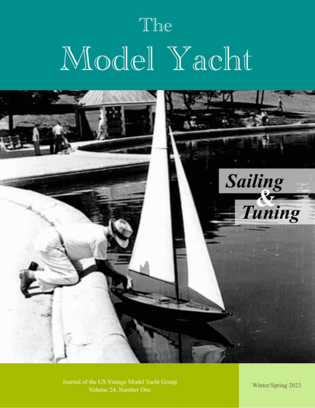
Winter/Spring 2023 The Model Yacht The Model Yacht is published three times per year by the US Vintage Model Yacht Group. Copyright 1989 to 2023 by the US VMYG. Reproduction for noncommercial purposes permitted; all other rights reserved. Other copyrights are maintained by the original holders, and such material is used here under the fair use provisions of the relevant copyright acts for nonprofit research and educational purposes. Editorial Address: John Stoudt 309 Sundance Drive Chester Springs, PA 19425 On the Cover: A free-sailing vintage sloop, possibly an Aboat, being tuned prior to launching in New York City Central Park Conservatory Water, around the mid 1950s. Membership Renewals: The annual membership fee will be due and should be renewed with the publication of the first journal of the calendar year. Please reference “Membership” on page 38 for dues amounts. Please use the form that accompanies this issue of The Model Yacht to complete your membership renewal. Requesting a sail number: The easiest way to request a sail number is to go here: https:// usvmyg.org/registration/ Then click on the class of the boat you wish to register and get a sail number for. A form will open. Complete the form, pay the fee, and everything will happen automatically. You will receive a number, issued by the class coordinator. The US VMYG is a 501(c)(3) corporation. The Layline By John Stoudt Definition: A layline is a straight line (or bearing) extending from the next mark to indicate the course a boat should be able to sail on the one tack in order to pass to the windward side of the mark. (vsk.wikia.com/wiki/Layline) Leadership Changes Bruce Richter usually art directs and assembles The Model Yacht. He and his wife are in the process of building a house and getting settled in Maine. He was unable to assemble Volume 23, Issue 3. Jeff Beck assumed that role while doing his other work and did a great job. Thank you, Jeff. Bruce is back working with us on this issue as they watch their new home take shape just down the street from where they’re currently renting. Bruce Richter and Alan Suydam have asked to be replaced as the Marblehead and Vintage 36 class coordinators. Colin Parker (VM) and Rob Dutton (V36) have assumed these roles. Additionally, Steve LaBrenz has asked to be replaced as the Social Media Coordinator. Chuck Lage has stepped into Steve’s role. Gudmund Thompson has also assumed the role of the Canadian regional coordinator, and he has been added to the editorial staff of The Model Yacht. Jim Linville turned over his Boat Yard responsibilities to Cliff Martin. Jeff Gros has agreed to provide construction advice to individuals along with John Henderson. Jim Freeze is working on the process of developing the model yacht database. Mike Denest will be assisting individuals with boat identification. The contact information of these individuals may be found on the About Us page on our website: https://usvmyg.org/about/organizationalleadership/ A special thanks to these outgoing members of the organization’s leadership team and kudos to those agreeing to step into those roles. We have a lot of good people in the organization making it work for you. Membership Dues We are holding the membership dues at the same level for 2023. The board believes we can continue to provide the services currently offered and the new ones discussed below for the same membership fee. 1
Winter/Spring 2023 The Model Yacht Inside The Leadership Team……….i The Layline…………………1 Barnacles………………17, 33 Seaworthy Small Ship Retirement Announcement…5 The Tuning Cycle…………..6 Bench Tuning Your Boat……7 Sails: The Source of Power…9 It’s Not the Slot! How Sails Really Work……14 Switching Gears and Sailing Fast.…………….….18 Tech Topic: Helm Balance.. .20 Carr High Twist Sail Handling Instructions.……..25 The Right Jibe..……………28 “My Boat Is Sinking!”…….30 Member Benefits In the near future the US VMYG will offer you additional member benefits. These include free access to all back issues of the newsletter/ journal and free downloads from two different sets of boat plans. The plan sets include our current plans available for purchase (1 free download per year) and a set of plans available exclusively to our members (2 free downloads per year). You must access these items via the member portal of the website. Facebook Following We have over 1,080 followers on Facebook. That is unbelievable if you think about it. There is a lot of interest in what we do with this hobby. Over half of our followers are from outside the US. I for one would like to figure out how to turn some of this interest into an increase in membership. Any ideas? Rules Changes The US VMYG recently realized that the V36 class rules excluded “high flyer” Vintage 36 boats. Because of this discovery, we rewrote the V36 rules to include these boats and make them eligible for regattas. This led us to make a few adjustments to the VM rules as well for consistency. These proposed rule changes were shared with the membership which led to questions, These questions lead us to make clarifications to both sets of rules. The revised rules can be found on the class pages on our website: https://usvmyg.org/classes/ The rule review process was undertaken by the following individuals: Jeff Beck, Rob Dutton, John Henderson, Colin Parker, Alan Suydam, and John Stoudt. A Boat Dryer………………34 Records Keeping Friendship-Rigged Nattingham 60…………….35 The US VMYG is collecting and storing all kinds of model yacht-related materials such as vintage model yacht video footage, rules development documents, plans, and other items on the “cloud”. If you have items, photographs, videos, records, or documents (electronic or hard copy) that you believe are valuable to model yachting, please contact us about possible inclusion in this archival effort. Resources………………….37 Membership Form…….…..38 2
Winter/Spring 2023 The Model Yacht The Model Yachting Center (TMYC) The development of The Model Yachting Center (TMYC), to promote, perpetuate, and preserve the sport of model yachting, which has its roots in the 1850s, is moving along well. This facility will include indoor ponds, outdoor ponds, workshops, boat shop, banquet rooms, food and beverage venues, displays, and archival space. The indoor and outdoor ponds would host year-round leagues and clubs along with local, regional, national, and international regattas. Illustration by Irwin Schuster This is an email that I sent out recently to bring a group of individuals up to date on the progress of this project. I am providing this update to a number of you who have contributed in one way or another to this project and to our Board of Directors. This project, to develop The Model Yachting Center, has started to gain energy rolling down a steep hill. All good stuff. Here is the timeline of how we got here: • Development of the initial brochure. • Spoke with a fundraiser who thought this was fundable. • Received an initial donation of $1,000. • That was matched by another donation of $1,000. • US VMYG received nonprofit status in May 2022. • We continued to reach out to others. • Received an anonymous donation of $5,000. • Spoke with HealyKohler Design (https://www.healykohler.com/). • The ideas they presented to us blew our initial thinking out of the water. No pun intended. They think of this as a Broadway Show. • We also spoke with feasibility experts about next steps. 3
Winter/Spring 2023 The Model Yacht • • • • • • • • Studied two museums that have become the example of where we want to go with this concept. Both of these are magical places. Tabarly Museum, France (https://www.citevoile-tabarly.com/en). Sailing Museum, Newport, RI (https://thesailingmuseum.org/). Met with the American Model Yachting Association board of directors and shared the concept with them. The AMYA will be partnering with the US VMYG on this project. The US VMYG will continue to take the lead on this endeavor for various reasons. We both agreed to begin fund raising for the next three phases of the project. a feasibility study further creative development development of a capital fundraising campaign Our next fundraising goal is to raise $150,000 to conduct the three steps noted above. We will work with AMYA to achieve this funding target. Members of both organizations and others will hear more about this in the near future. I would like to thank each one of you for your varied support for this project. If you have any questions or comments, please feel free to contact me (usvmyg.tmyc@gmail.com) and copy Chuck Lage, our project manager (chucklage@yahoo.com). We are in the process of forming an ad hoc committee of the US VMYG board. If you know of someone who would be a good member of this committee, please forward their name and contact information. We are looking for a few good, creative, connected individuals. Thank all of you for your support. Cheers, John Y. Stoudt, President US VMYG Photo courtesy of Tabarly Museum, Lorient, FR 4
Winter/Spring 2023 The Model Yacht The brochure included with this issue is a revision to the one that was shared with you a while ago. Please take some time to review this new version. There is a lot more clarity and information. It tells an enhanced story about the evolving vision of TMYC. Your tax-deductible donation will help us make the next steps a reality. Join the growing group of contributors and make your taxdeductible donation to further develop this concept and help https://usvmyg.org/giving/ bring TMYC to fruition. Your donations are being accounted for within the budget of the US VMYG solely for the development of The Model Yachting Center. 5
Winter/Spring 2023 The Model Yacht The Tuning Cycle This article was originally published in Model Yachting, Fall 2017, Issue 189, p. 14. It is reprinted here with permission from The American Model Yachting Association. Article by Bob Sterne T uning is a cycle, or more correctly, a spiral. Each trip around the spiral brings us closer to the center, the ultimate state of the boat tune. At the beginning of each cycle, we assess the wind, water, and boat performance, and try to improve upon the previous cycle. Sometimes nature throws us a curve in the form of a change of wind or water conditions, and knocks us back a row or two. We have to claw our way back up again. This is what makes sailing such a challenge. 6
Winter/Spring 2023 The Model Yacht Bench Tuning Your Boat Article and images by John Stoudt The last thing to do before you put your boat in the water for the “on the water tuning” is what I call bench tuning your boat. This is done after you have set up the rig and verified that it is true side to side and that the mast is plumb fore and aft. Place your boat on its side on the edge of a workbench or table with the rig installed (see Illustration 1). Make sure that there is an overhang that allows the booms to move up and down without hitting the edge of the bench. At this point you will tie off the sheets coming out of the boat and those attached to the booms. Illustration 1. Follow these steps: 1. Turn on the boat and the radio. 2. Place the sail control in the closehauled position, left-hand transmitter stick (throttle) toward you. If it does not point toward you, reverse it now. 3. Set the sheet adjustment bowsie in Illustration 2. the middle position on each boom (see Illustration 2). 4. Holding the boom in the close-hauled position, estimate halfway between the boom and the fairlead where the sheet exits the boat (see Illustration 3). At this distance from the fairlead tie an O ring to each sheet with a half knot (see Fig. 1 on following page). You will complete the knots later. 5. Clip your sheet hook to each O ring. Illustration 3. (see hooks in Figs 2 and 3 on following page). 6. Pull (by hand) one boom at a time into the close-hauled position and pass the sheet line coming from the boom through the hook and tie it off with a half knot. It is important to make sure that the boom is in the close-hauled position. Do this with each boom. 7. Check each boom’s position and adjust the hook and ring now if necessary. 8. Using the transmitter, adjust the sails in and out. Pay particular attention to the running position of sails when fully out. 7
Winter/Spring 2023 The Model Yacht 9. Fig. 1. Acceptable O rings. These O rings are all effective. The three on the right are solid O rings. The three on the left are split O rings. I prefer solid O rings. Regular round split rings allow the line to get caught in the splits and release as the sails work in and out. The six rings pictured cannot do that. The solid O rings have no split. The other rings are an elongated shape, and the splits are on the sides: therefore, the rings cannot rotate, so the lines cannot disengage. Fig. 2. Unacceptable hooks. These hooks have external catches that may snag the sheets. At this point you may have to adjust the end point at the farthest travel (running) position when the sheets are out. The booms should be set between 85° and 90° (jib) and 80° (main) from the centerline of the boat. Make sure that the mainsail is not deformed too much by the shroud when the sails are out. 10. You can adjust these angles by using the travel adjustment function in the radio and bowsie on each boom. Note: The lower most shroud should always be set up as the rear shroud on the shroud rack. This will minimize the impact that the shrouds have in deforming the mainsail. If the upper shroud is in the rear position, it will have significantly more impact on the shape of the mainsail when running. 11. When you are satisfied with the travel of the booms, complete the knots on the O rings and the hooks. CA the knots, cut each end of the line about ⅜ in long, and heat seal the ends with a grill lighter or CA them. Make sure your sheet lines are of adequate strength and have Kevlar fibers in the weave. These take a lot of abuse. Now is the time to make your basic tuning adjustments for a medium air day: 5–7 knots. Set the sail camber. Tension the back stay. Check the twist in the sails. Actual sail adjustments will be made pondside based on wind conditions. Setting the boat up in neutral positions (for medium wind) is accepted practice. All of the hooks and O rings are available on Amazon using the following descriptor in the search feature. Fig. 3. Acceptable hooks. These hooks all have a captured end when they are closed so they will not snag the sheets. The hooks on the right are difficult to engage and hard to find. The ones in the middle are readily available but tend to be too light weight. The ones on the left are very sturdy, have an enclosed hook, and come in varying weights adequate for our application. O Rings • high strength solid ring for fishing • teardrop fishing split ring • stainless-steel fishing oval split rings Hooks • stainless fishing line snap connector • stainless-steel snap swivel (remove the swivel for this application). 8
Winter/Spring 2023 The Model Yacht Sails: The Source of Power. An Introduction to Model Yacht Sails, Part 1 Article by Rod Carr This article was originally published in Model Yachting, Winter 2003, Issue 130, p. 18. It is reprinted here with permission from the American Model Yachting Association. The first job of a new skipper is to learn the specific nomenclature that describes the sails. There are a handful of terms, and the quicker they are added to your vocabulary the easier it will be to communicate with your sailmaker and understand the specific techniques described for sail set, trim, and tuning. The suit of sails consists of a mainsail and a jib. The word “suit”, like pants and a jacket, not “suite” which is an expensive multi-room arrangement in a hotel. Figure 1 provides a profile view of a sloop-rigged mainsail and jib. The names of the corresponding edges of each sail are the same: luff (leading edge), leech (trailing edge), and foot (bottom edge). The names of the corners likewise correspond: head (top forward corner), tack (bottom forward corner), and clew (bottom after corner). Now, each edge of the sail may or may not be cut straight. Starting from the bow: Jib luff — if cut concave, the maximum concavity is referred to as jib hollow, or jib luff allowance (JLA) It is usually measured in 1/32-in increments, and reported as a 4 or a 6 meaning 4/32 or 6/32 inches of concavity near the midpoint of the curve. Single panel sails may have no concavity, or they may have some convex JLA to provide the extra cloth needed in the sail to develop camber, the airfoil shape required for good performance. Remember that the jibstay will sag under wind pressure and that the jib luff will be forced to assume that shape. Figure 1 Jib foot — most jibs are cut with extra cloth outside the straight line drawn between the tack and clew. The amount outside is referred to as foot round and is usually reported in inches. Most jibs are rigged with “loose feet”, meaning that the sail is attached to the jib boom or club at the tack and clew only. If the sail will be attached along the jib club, there will likely be very little foot round. 9
Winter/Spring 2023 The Model Yacht Sail Shape Jib leech — Class rules typically allow extra cloth to be added to the sail between the straight line distance between the head and clew. This extra cloth is called leech roach and is reported as the maximum distance outside of the straight line. To prevent this extra cloth from folding over, support is added in the form of battens: short lengths of stiff material attached to the sail or slipped into pockets that terminate on the after edge of the leech. The number, length, and placement of battens are controlled by Class Rules. In general, maximum batten length is about 2.5 ⨉ leech roach. Modern sail materials do not require batten support as much as the old cotton sails did, so they are very often eliminated from jibs to prevent jib leech from being “hard” or flat. Figure 1B shows a cross section of a sail. The wind blows from left to right. The dimension “L” is the chord across the sail, a straight line from luff to leech. The % camber is found by dividing the maximum depth “D” by the chord “L”. Model yacht sails typically have cambers which vary from 5% for flat sails, to 15% for quite full sails. The position of maximum draft is found by dividing “M” by “L”. Mainsails generally have maximum draft located at 40% to 50% of chord, while jibs can be successful with maximum draft located at 35% to 40%. Sails with maximum draft forward have good acceleration, don’t point particularly well, and have a fairly low top speed potential, generally a good form for light winds. Sails with maximum draft aft have good pointing ability, have good top end speed culpability, and are recommended for medium to heavy winds. Draft stripes are often put on model yacht sails to assist in visualizing the shape in the sail when full of wind. Mainsail luff — Most mainsail luffs are cut with a convex shape, with some amount of extra cloth outside the straight line between head and tack. The amount of extra cloth outside the straight line is called luff round, or Main Luff Allowance (MLA). On a sail with a 67-in luff, the MLA is typically ¼ inches and is reported as such. When set on a straight mast, the extra cloth moves back into the body of the sail increasing its camber or depth. Adjusting the mast by bending it forward at its midsection pulls the extra cloth forward, thereby flattening the sail for higher wind speed conditions. Sail Construction Sails come in two general varieties of construction: single panel, when the entire sail is one piece of cloth without seams, gores, or cuts in the body of the sail and paneled, where each sail is made up of panels or strips of cloth, attached edge to edge with tapered seams to induce three-dimensional shape in the sail when filled with wind. Mainsail foot — Same comments apply as for the jib foot. Mainsail leech — Same comments as for the jib leech. In addition, most mainsails will be constructed with battens, as mainsail leech roaches are usually larger than jib leech roaches. Care must be taken that the battens are not so stiff that they flatten the after third of the sail to look like a barn door. Battens on modern sails assist in shaping the after parts of the sail; the cloth is generally stable enough to hold itself fairly well, needing just a bit of help. 10 Single panel sails of a woven material are typically encountered in the construction of “kit” boats, because single panel sails are much less costly for the kit maker to provide. They are also found in several AMYA racing classes, such as the CR 914 and Soling One Meter, where the Class Rules require either kit sails only or aftermarket single panel sails cut to a specific size. The details of successful set, trim, and tuning of single panel sails is an entire subject in itself. Your sailmaker should be able to provide you with guidance if you are purchasing sails of this type from him.
Winter/Spring 2023 The Model Yacht At the very least, he should inform you of the JLA and MLA measurements so that you will have a starting point for setting up your initial mast shape, and backstay tension. Single panel sails must be full of air, so that the cloth can stretch under the wind loading and can begin to take on the cambered shape necessary for drive. Paneled sails are used in the greater proportion of racing classes and also in scale models that are going to be operated on the water. They provide superior performance because the airfoil shape that provides drive for propelling the hull is built into the sail. Most use a membrane material such as a mylar sandwich with load carrying fibers, or mylar film. These modern materials don’t stretch, so the cambered shape must be built into the sail with tapered seams that hold the panels together. Fig.2. Sail corner rigging down the jib club to some some sort of a tension adjustment like a cleat, 3-hole bowsie, or other device. The clew is constrained in the vertical direction by something as simple as a loop of sheet line tied through the clew grommet and led under and around the club. A second line, called the clew outhaul, leads aft to the end of the jib club and provides for adjusting the position of the clew along the club, controlling the fullness of the foot and the bottom third of the jib. Sail Attachment A sail is attached to the spars by each of the three corners and by the luff of the sail to either the mast or the jibstay (see Fig. 2). In the case of the jib, almost all jib luffs are fitted with a hem into which which the jibstay slides. This supports the sail along its length and makes for a smooth and clean entry where the wind meets the sail. The luff hem method eliminates scalloping which can happen with the tubes, and it distributes the wind load evenly over the entire luff. Some jibs are mounted using little hollow tubes affixed to the sail that are slid over the jibstay. The sail tubes provide for excellent swiveling as the sail tacks, but produce point loads where they attach to the sail, and this can cause the sail to wear out prematurely. The corners of the mainsail are rigged the same way. The luff of the mainsail must be mated with the mast, and many methods have been developed over the years. The mast material drives part of the solution, while the size of the boat and/or the class rules under which the boat will sail may provide other opportunities or constraints. Figure 3 shows a series of approaches to this problem, certainly not exhaustive by any means. Smaller classes, such as the 36/600, Victoria, Fairwind, International One Meter, and US One Meter that use round mast materials like aluminum or carbon fiber tube use the mast loop method (Fig. 3A) with good success. The head of the jib usually contains a grommet to which is attached a halyard, For ease of adjustment, the halyard is fixed, usually up at the jibstay attachment point. Tension is adjusted on the sail luff by use of a downhaul, which is tied to the tack grommet, led to the jib club, and back about halfway Aerodynamically it provides the best leading edge, which gets traded off against a shorter sail lifetime 11
Winter/Spring 2023 The Model Yacht since the luff is attached at discrete points. Jackwire method (Fig. 3B) work well, with various methods employed for holding the wire to the mast. We show a row of cotter pins set through the mast with “windows” cut in the sail for clearance. Dress hooks have been used for attachment to the jackwire, but seem typical of only vintage boats these days. Extruded masts like Bantock “Groovey” and the Ozmun “Goldspar” are amenable to the standard bolt-rope (Fig. 3C). This method produced generally poor sail shape at the exit to the mast slot, and poor hinging ability in light air. Jackwire methods using mast slides or other attachment methods (Fig. 3D) product better hinging and longer sail lifetimes. Mast slugs or heads directly attached to reinforcement patches on the luff are also tangent to where the luff hits the table. Adjust the position of the clew holder by moving it parallel to the luff to adjust for twist in the sail. Moving the holder toward the head will allow the upper leech to sag and twist off. A small amount of twist should exist in the sail. Photo 1 shows a jib which has been set up like this. Use a straight edge between the head and tack and measure the distance to the luff in 32nds of an inch. This is the JLA for that sail. You now know how much the jibstay must sag to exactly match the shape cut in the luff of the sail. The higher the wind blows, the more sag will occur. So in general, model yacht sails are cut with somewhere between 4/32 and 10/32 inches of JLA. The amount depends on the target wind range and on the length of the luff itself. Sail Setting Assessment Success in sail setting requires an understanding of the match between the flexible sail and its mounting component. For mainsails, the mast shape must be matched to the shape of the mainsail luff for a good match. For jibs, the jib luff shape needs to be cut so that it harmonizes with the sag in the jibstay which results from wind pressure on the sail. Fig.3. Mast sail attachment methods. If your sailmaker doesn’t tell you your jib luff allowance, you must measure it. Tape the leading edge of the sail at the head and tack to a flat surface. Make a clew holder by drilling a bunch of holes in an 18-in long piece of 2⨉2 screwed into a plywood base which can be weighted, then put a 4in piece of pointed stiff wire in the appropriate hole to hold the clew. Elevate the clew of the sail until the sail swoops down toward the luff and becomes just While the jib is standing there, observe it for its general characteristics. Where is the point of maximum draft? Is the leading half of the sail smooth and gently rounded? A few pictures taken with a digital camera can be printed out in black and white and measurements can be made which allow camber, maximum draft, entry angle, and so on to be calculated. The shape the sail shows here is caused by gravity, not wind. The weight of the typical sail (1.0 oz/yd2) can be equated to a wind pressure from a 1- to 1.5-mph wind. So one should expect some changes in shape once the sail is on the boat on the water. Mast sail attachment methods. 12
Winter/Spring 2023 The Model Yacht Photo 1. Finding the jib luff allowance. Mainsails are also amenable to inspection by the same method. MLA must be determined for the luff of the mainsail so that a proper mast shape can be matched to the shape of the mainsail luff. Photo 2 shows a sail with the head and tack taped down, and clew elevated. The straight edge along the luff allowed measurement of 3/32 in of luff hollow to be determined. This means that a mast match for this sail requires for the center of the mast to be pulled aft by 3/32 in. As wind speed increases, masts usually bow forward under increased backstay tension. This sail will not respond well to that change in mast shape, so is likely intended for use in only the lightest of airs. We observe that this is a very “draft-forward” sail, so good for acceleration, but with a low top speed capability. Pointing and top speed are not so important in light air, where acceleration after tacks and mark roundings is critical to racing performance. Notice that the leech area is very flat, caused by extremely stiff battens. Initial Close Hauled Tuning With the sails on the boat, and the boat on its side so that you can sight down the mast, the following are good starting points for tuning your new sails for windward performance in light air. Photo 2. Main luff measurement. Mast shape should be straight fore-and-aft. This allows the mainsail luff round to give added fullness to the mainsail. 1. Set the mainsail sheet so that the bottom batten of mainsail is parallel to the main boom. 2. Set the main boom vang so that the sail twists off aloft until the top batten is parallel to the main boom. 3. Adjust the jib sheet so that the jib boom points just inboard of the side shroud chainplate. 4. Adjust topping lift so that jib twist, when the jib leech is viewed from aft, matches the twist set in the mainsail. Now you are ready to begin a reiterative process searching for optimum performance. Put the boat on the water, check for boat balance. If too much weather helm the rig may need to be moved forward. If only a little weather helm, you may need to trim the jib in slightly. Sailing with a partner who doesn’t make a change while you do will give you a benchmark against which you can gauge improvement. Further information on tuning can be found in Tuning Guides that some model yacht sailmakers include with their products. You can also delve into books written for people who sail boats that they insist in sitting in! A couple good references are: Sail Power by Wallace Ross (1975) ISBN 0-394-47151-2; and Sail Performance by CA Marchaj (1990) ISBN 0-07-040250-7. 13
Winter/Spring 2023 The Model Yacht It’s Not the Slot! How Sails Really Work Article by Bob Szezepanski This article was originally published in Model Yachting, Winter 2011, Issue 166, p. 21. It is reprinted here with permission from The American Model Yachting Association. The physical size of a Victoria makes it a great platform to study and experiment with sail design, sail trim, and the interaction between the mainsail and jib. The sails are small enough to be easy and inexpensive to build, yet are large enough to study the effects of design and trim experimentation. Early in the process of trying to design the “perfect shape” for model yachts, I bumped into a classic urban legend that is applied equally to model and full-sized sail theory. the lift is known as circulation flow. Circulation is the flow of air created around the sail due to its presence in the wind. Circulation flow makes the low-pressure and high-pressure areas possible and creates lift, as shown in Fig. 1. Everyone has heard how important the slot between the jib and mainsail is relative to optimal sail trim and performance. It is generally thought that the slot increases airflow over the main, thus improving its efficiency. Too open (not enough air squeezing) is bad, just as too closed (too much squeezing) is bad. As in Goldilocks, the squeezing has to be just right. Once while crewing on a fullsized racing yacht, I was strongly admonished for standing in the slot area, because I was “disrupting the air flow” and, therefore, negatively affecting boat speed. All this is, well… Wrong! You can see that the circulation flow opposes the apparent wind flow on the windward side, slowing it, thus increasing pressure. On the leeward side, the circulation flow speeds up the airflow, thus reducing air pressure. According to Bernoulli’s Principle, we now have the formula for lift. If you have doubt that circulation flow exists (and many do), I offer the following homework assignment. Fill your bathtub with about six inches of water. When the water becomes calm, sprinkle ground pepper, or bath powder (anything that has small particles that float) over the entire surface area of the water. Take a small piece of cardboard and Most know that sails generate lift by creating a low-pressure area on the leeward side of the sail and a high-pressure area on the windward side. How this happens, it seems, is not widely understood. The phenomenon that really creates 14
Winter/Spring 2023 The Model Yacht carefully bend it into the curved shape of a sail. slowly put the cardboard “sail” in the water and then move it across the tub. Remove the “sail” when you reach the other end. What you will see is shown in Fig. 2. As you might expect, each sail has its own circulation flow, but wait: the flows actually oppose each other in the slot! It is another highpressure area! The wind is not squeezed too much or too little, it is practically stopped. Therefore the circulation flow relative to both sails looks like what you see in Fig. 4. As the “sail” starts to move, it creates a vortex, known as the starting vortex, which initiates the circulation flow, which in conjunction with the apparent wind generates lift. Both circulations will be visible. Visualizing or seeing the circulation flow also helps to understand upwash. The circulation flow that opposes the apparent wind causes upwash. The upwash causes some of the apparent wind to be pushed over to the leeward side of the sail, speeding up the airflow, which further lowers the leeward side pressure. Increasing upwash increases lift and improves the efficiency of the sail. Understanding upwash will prove useful when sail trim is discussed later. The flow surrounds both sails, and the slot essentially becomes no factor. The wind “sees” both sails as one big airfoil. How can this be? We have all seen backwinding of the main, caused by the jib, but it is not, as many think, from the size of the slot. The cause is the main either being set too full, or not being sheeted in enough relative to the jib, or both. What actually causes the backwinding is the jib’s circulation flow hitting the leeward side of the main and partially distorting its circulation flow. The fix is a combination of either flattening the main or trimming the main in more, doing both, or easing the jib if the main is already flat and fully trimmed in. These actions fix the flow so that it is again parallel to both sides of the sail and no backwinding occurs. Now that we know, and maybe have seen, how a sail works, we can consider what is going on in the slot. Adding a jib to the earlier figure and drawing in the circulation flow yields what you see in Fig. 3. Knowing all this provides interesting implications for sail trim. The circulation flow around the 15
Winter/Spring 2023 The Model Yacht mainsail increases the upwash of the jib, causing it to generate more lift than it would without the mainsail. The jib, in turn, speeds up the wind on the leeward side of the main, further lowering the pressure and also increasing the lift that would occur without the jib. Since the circulation flow around both sails is similar to the flow around one (See Fig. 4), it makes sense to approach trimming both sails as one. Much like an airplane wing, the overall camber and position of both sails can be changed to fit the conditions. The jib can be thought of as the leading edge, and the mainsail can be thought of as the trailing edge of a wing and trimmed accordingly. in Fig. 6, Position B. To reduce lift and to minimize drag, while increasing speed, flaps on an airplane wing are raised above the normal position to what is called a reflex position. (The entry angle is unchanged from the nominal position.) The sail trim approximation of this is flatter sails with the main trimmed closer to the rail, as shown in Fig. 6, Position C. The forestay and jib luff have maximum tension, and the mainsail is set draft aft and has been twisted to open the leech and minimize drag. The result is a high-speed shape suitable for high wind. In Position A, the airplane wing is in its nominal shape for mid-range flying speeds. This is similar to sails being trimmed for mid-range winds as shown in Fig. 6, Position A. Both sails have nominal camber and are set for the best lift-to-drag ratio. Lowering the flaps and changing the entry angle (as shown in Fig. 5, Position B) on a wing increases camber and therefore lift at low speeds. This, too, can be approximated with sails. Setting a more camberforward jib (tensioning the jib luff to either move draft forward, or at least preventing it from moving aft) in conjunction with lower forestay tension is similar to changing the entry angle on the wing. This jib trim, combined with deeply cambered, (eased outhaul) fully sheeted-in mainsail with draft more forward replicates lowering the flaps. The result is a powerful overall shape suitable for light air, as shown 16 In addition to the misconceptions about the slot, setting sail twist is often approached incorrectly. It is a problem mostly prone to model yacht skippers. It is widely accepted and has been proven that the wind gradient (angle of the apparent wind) moves aft and increases speed as you move toward the top of the sail. Therefore, the sail must be twisted to accommodate the gradient change. This is completely true and a
Winter/Spring 2023 The Model Yacht preferred, since wind gusts and increased heel angles increase upwash. Slight over-twist helps prevent stalling during these situations. large factor on full-sized boats when your mast is measured in feet. It is not the reason to set twist when your mast is measured in inches (model yachts). Most, if not all, models are sailed in the boundary layer. (Less than 10 feet above the water.) A very small wind gradient in this region does exist, but is completely negated, relative to the boat, by the apparent wind the boat generates by simply moving, even at very low speeds. Because of the small scale of models, the gradient force vector is so small compared to the apparent wind vector that it can be completely ignored. If this is true, why then is getting twist correct so important? The reason is the upwash that is created by the circulation flow that was described before. Upwash causes the apparent wind to move aft as you move toward the top of the sail, much like a wind gradient. Back-sweep (the shape of the jib) increases upwash, while fore-sweep (the shape of the main) decreases upwash. This is why jibs need to be designed and set with more twist than the main. More upwash requires more twist. For optimum trim, you need to twist the sails to accommodate the upwash being generated. Actually, very slight over twist set in each sail is A last look at the circulation flows (Figs. 3 and 4) yields another interesting conclusion. More airflow (upwash) will be created around the jib if the sails are set as close to one another as practical. Being close, less air will leak through the slot. The increased upwash, in turn, increases the air speed on the leeward side of the sails, and the efficiency of both is improved! This is among the principle reasons why overlapping jibs (Genoas) are so effective on full-sized boats. The dynamics of the slot, it turns out, is quite different from what the urban legend holds. Understanding circulation flow, which causes lift, upwash, and defines how sails really work, provides useful insights for optimizing sail trim for performance racing. This article is based on observations from testing model yacht sails and the original work of Arvel Gentry, C.A. Marchaj, and Martin Kutta. Barnacle Bread and Butter Construction— Someone recently asked, when did bread and butter construction first show up in model yachting? According to Martin Bandey (president of the VMYG in the UK) “Hulls were joined on the waterline before 1900, although folks did not rely upon animal glue entirely. Daniels and other builders later (say 1910-1930) used a system of copper wire stitching in addition to ‘glue’, but I think you will find it was not until 1930ish that we started to have the early ‘waterproof’ glues, which of course as we find today did not last forever.” Graham Reeves (former president of the VCMYG says “Reference the Bread-and-Butter method of building model boats. I think this goes back hundreds of years. The oldest book I have that mentions this method is the Biddle book of 1879.” The US VMYG editors found an additional piece of information regarding the fastening of the lifts. Flathead wood screw were carefully placed in between the lifts to ensure construction integrity. 17
The Model Yacht Winter/Spring 2023 Switching Gears and Sailing Fast Article by Richard Kahle This article was originally published in Model Yachting, Fall 2017, Issue 189, p. 12. It is reprinted here with permission from The American Model Yachting Association. and forth from one tack to another to simulate air pressure. The wife and kids often think I am flat-out crazy. At the lake, you can do the same by resting the keel on a towel laid on the ground or by just holding the boat up in the air. This simulates the view of being on deck looking up at your sails. One of the most difficult things about sailing model yachts is the fact that you are not on board to see what is going on. Yes, when far away, it is hard to judge distances to marks and competitors but getting your sails trimmed right is certainly one of the biggest challenges. This article is an attempt to explain my thoughts and ideas on initial setup of an EC12 yacht and the tweaking and tuning that follow as the wind velocity changes. I will say that I have developed an eye for how things should look, and my mouth and fingers don’t follow well. There is still plenty for me to learn. Most of the venues where we sail on the East Coast are located on small lakes with wind obstructions and are rarely on open water. Most of the time, the breeze might be around the bottom of the course but lightens as you get near the top mark. If you are too tight in the lighter air near the weather mark, you are going to get killed. Often, there is much maneuvering here and acceleration is key. At the same time, if you don’t tighten the leech of the mainsails going upwind in the breeze, you are going to be out-pointed. So, you have arrived at the lake early in the morning to get your boat rigged and prepared, well before the skippers’ meeting. A layer of fog is hovering above the racecourse, and the only ripples on the water are from ducks or the fountains at Elon. You set your sails up for light air and wait for the breeze to fill. As a starting point, what I look for are the middle battens on the mainsail to be parallel to the boat’s centerline and the leech of the jib pointing straight aft. These adjustments are set with the vang and the topping lift. The problem is that when the boat lies on its side you have only gravity to help you judge the amount of twist in your sails. This is not a big deal in the light stuff as there is very little pressure while sailing. It is virtually impossible to predict on land what the actual pressure will do to your sails on the water as the wind builds. Sometimes I will do what I call armchair sailing. At home, while examining a new set of sails or getting pumped for a regatta, I actually sit in my favorite recliner, with the boat rigged on my lap and flop the sails back Therefore, “switching gears” and twist adjustment is important. Since you cannot adjust your vang on the go I rely on sheet vanging. This is where the mainsheet is over tightened so the boom is actually pulled down toward the deck. The RMG sail winch with the spiral drums really comes into play in the EC12 in these conditions. The fine adjustment allows you to find the sweet spot, in order to keep your telltales on the leech of the main flying. Setting Up Here is what you need to do to set up for this. When using the RMG winch the fine trim on the sheet stick of your transmitter should be all the way in. Adjust the bowsie on your main sheet to the appropriate leech tension (twist) for the maximum wind speed you expect to see in the 18
Winter/Spring 2023 The Model Yacht conditions you are sailing. Ease your sheets a hair with the trim lever or stick. Your vang should be set so that the boom lifts a little, giving you the nominal twist setting for the average pressure you expect to see. Sailing the EC12 in this fashion brings the main boom to almost centerline. Be aware of your boat speed in relationship to competitors around you, for it is really easy to stall in this mode. If you feel slow, let off a bit and go faster. If you are moving well, tighten up and point high. If your sails are worn and abused, stick with your original plan. Using the Jib-Trim Feature One last thing I want to mention is the use of the jib-trim feature, which is allowed in the EC12 Class. There is a misconception among some that tightening up the jib trim will make you point higher. It is true that trimming the jib in farther will reduce the entry angle of the sail, allowing you to sail a little closer to the wind before the jib begins to luff; however, in that the EC12 has a fractional rigged sail plan, most of the drive comes from the mainsail. The pointing ability of the boat is dependent on your ability to properly trim the main. Once you have achieved this, the general rule is that you trim the jib to match the main. First adjust the topping lift so that the leech of the jib matches the point of maximum camber of the main. In light air go for a larger slot to allow for better airflow, with the jib boom pointing just inside the shrouds. As the wind picks up, trim the jib until it causes the main to backwind and then ease it back out slightly. In heavy air, you can overtrim the jib and ease the sheets slightly to depower the main, which helps to hold the bow down and reduce weather helm, be it upwind or on a reach. Unlike the main, in most conditions I like to set the bowsie adjustment on the jib sheet slightly loose, or as loose as I would want it sailing upwind in the given conditions; then use the trim feature to dial it in. Rarely would I allow the jib to be sheeted out beyond the normal setting. In fact, the jib trim mechanisms in the boats that I have built are not designed to do so. Final Thoughts Without a doubt, there are many factors besides sail trim that contribute to podium finishes. Fortunately, with the class as well documented, as it is today, and the amount of helpful information available, most of the boats actively racing today are well built and properly ballasted. With a good set of sails and some general tuning knowledge, skippers can now get their heads out of their boats, focus on tactics and boat handling, and start winning races. In my opinion, the class has come a long way in the past six-to-eight years. There used to be larger performance gaps among the boats, from which to take advantage, but that is no longer the case. These days with a bad start and a mix-up in the crowd, it’s all over. Notice of Race United States Vintage Model Yacht Group 2023 National Championship Regatta Series October 13 – 15, 2023 Sponsored by the US Vintage Model Yacht Group and hosted by Chester Springs Model Yacht Club The sailing location is Tel Hai Camp and Retreat Center 1101 Beaver Dam Road, Honey Brook, PA 19344. NOR: https://usvmyg.org/wp-content/uploads/2023/02/USVMYG-2023-NOR.pdf 19
Winter/Spring 2023 The Model Yacht Tech Topics: O Helm Balance with simple calculations of Center of Effort and Center of Lateral Resistance Article and photo by John Henderson ne of the very first steps in setting up a new boat is getting the helm to “balance.” Balance refers to how the boat tracks without constant adjustments to the rudder. Balance preferences may be subtly different for different skippers. Some folks like a boat to track in a straight line when left to itself. Others prefer a slight tendency to “head up” (turn toward the wind) in response to a puff. No one likes a boat that tends to head down (turn away from the wind). weather and it imposes a similar favorable angle of attack to the keel. Note that I said small rudder offset—a large offset just generates drag. The argument for heading down There is none. This is called “lee helm” and should be avoided. A boat with lee helm wants to head away from the wind in a puff, which increases the heeling forces at a time when they probably should be decreased. Course corrections require turning the rudder in a direction that moves the stern to leeward, which is the opposite of what you want to do on the upwind leg. The argument for tracking straight It is often the case that at least part of the race course is far enough away that seeing the model boat’s behavior is difficult. It can be reassuring if you know that the boat will continue in a straight line without rudder input. This is very difficult to achieve, which is why self-steering gear was invented to control models before the days of remote control. The force vectors from the sail and hull change with heel angle, so a puff or lull will alter the course unless the rudder is moved. Achieving helm balance depends on establishing the right relationship between the Center of Effort (CE) of the sail plan and the Center of Lateral Resistance (CLR) of the hull. We will discuss first how to locate these Centers and then consider the optimum relative positions. The argument for heading up This is known as “weather helm”, because you move the tiller to weather (toward the wind) to bring the boat back to its course. For dinghies, this behavior can be a safety feature because it turns the boat so that the sails luff in a strong puff, even if the skipper fails to react. For models, the existence of weather helm can be a form of feedback to the skipper, because it gives a visual indication of the forces of wind and water on the model when we lack other kinds of feedback. One can even argue that a small amount of weather helm helps a boat get to windward, because the required small rudder offset to keep the boat on a straight course actually moves the stern a little to Finding the Center of Lateral Resistance (CLR) of the hull I will briefly describe the traditional methods and then introduce a third method that I find superior. The intuitive approach is to float the hull and push on the side with one finger. Move your finger toward the bow or stern to find the spot that causes the boat to translate sideways without twisting. This is the CLR. The problem with this method is that it depends on having a completed hull, so fixing surprises is difficult. 20
Winter/Spring 2023 The Model Yacht The usual textbook method of finding the CLR is to balance a cut-out of the profile view of the hull’s underbody on a straight-edge (a ruler) that is perpendicular to the waterline. The balance point is the CLR. The underbody shape is traced from the profile lines drawing; the “underbody” is all the parts of the hull from the waterline downward. Do not include the topsides (the hull that is above the waterline). You must use stiff plywood or cardboard. will use it to calculate area instead of volume). An explanation of Simpson’s Rule can be found in many books (e.g., Skene’s Elements of Yacht Design) and also in the US VMYG online Design articles at https://usvmyg.org/planning-andbuilding-scale-models-that-sail-part-2-designcalculations/. Instead of using the sections drawings to measure the area of each section below the waterline, we will use the profile drawing to measure the linear depth at each section from the waterline down to the keel. The same section numbering conventions and Simpson multipliers apply.The measurements are taken directly from the profile view in the plans, and the calculations take about 15 minutes. Fig. 1 shows a profile of an example hull containing only the lines relevant to this discussion. The positions of sections 0 through 8 are indicated. The solid portions of these lines, with arrowheads at each end, are the belowwaterline station “depths” that are used to compute the CLR. (Note that the particular numbers for the example in Table 1 refer to a 42in Unrestricted Class model that I am designing and building based on LF Herreshoff’s Stuart Knockabout. Fig. 1 is a representation, including some of my modifications. The original plans are available from The Mystic Seaport Museum.) Finding the CLR with a cardboard cut-out. My own preferred method to determine the CLR location is something that I have not found described in the literature, but which I think is analogous to the usual method of finding the Longitudinal Center of Buoyancy. I use Simpson’s Rule (the same rule we have used for displacement calculations, except that now we Fig. 1. Measuring for CLR. 21
Winter/Spring 2023 The Model Yacht The section depth measurements are entered into a Table like Table 1. The first column is the Station numbers, from Station #0 up to the station at the aft end of the LWL, which must have an even number. The second column shows Simpson’s Multipliers – note the pattern of 1,4,2,4,…2,4,1. The third column lists the LWL-to-keel distances for each station (called “station depth”). The fourth column (“Functions”) is the result of multiplying each station depth by its corresponding Simpson Multiplier.The fifth column (“Moments”) is the product of each Function and the Station Number from the first column. Sum up the column of Station Functions and also sum the column of Moments. The position of the CLR is found by dividing the sum of Moments by the sum of Functions. Note that this result is the number of stations (and fractions thereof) aft of Station #0, so a result of 4.6 stations aft of #0 means that the CLR is 0.6 times the station spacing aft of Section #4, as indicated in Fig. 1. There is discussion in the literature (and some disagreement) about whether or not the rudder should be included in this underbody profile shape. For models—which typically have an oversize rudder relative to full-size boats—I think the rudder should be included. I base this on observations of my own models. A compromise argument can be made to use half of the rudder’s profile area. I should note that the accuracy of this CLR calculation 22 improves as you increase the number of station depth measurements. For example, with reference to Fig. 1, you will notice that virtually the entirety of the rudder lies between Stations #6 and #7, so the shape of the rudder is not really captured by this set of sections. It would be better to double the number of sections (which would locate a new section midway between #6 and #7) so that the rudder area will be measured. Note that you cannot simply add a section where you might like one. The station spacing must be uniform over the entire LWL, so stations must be added between all of the existing stations. (In fact, when calculating for the actual model, I used 16 stations instead of the 8 in this deliberately abbreviated example —and the CLR moved from 4.6 to 4.7 stations aft of #0.) It is easy to add more such vertical lines to the profile view on the plan, and there is no need to draw the shapes of these new sections on the rest of the drawings. The increased accuracy that a greater number of stations provides is likely important for underbodies with high aspect ratio fins and separate rudders. We want to capture at least some of the details of their shapes. There might also be cases where there is a gap between the bottom of the hull and the trailing edge of the rudder or between the hull and a section of the ballast bulb. In these cases, the “depths” recorded in Table 1 should be the sum of all the elements (including rudder or fin) that are crossed by the section lines, so add the dimension of (for example) a ballast bulb to the hull measurement above it.
Winter/Spring 2023 The Model Yacht Finding the Center of Effort (CE) of the sail plan Relative positions of CLR and CE The process for locating the CE of the sail plan is welldocumented, including in the Design section of our US VMYG website (see reference above), from which this description is taken. Referring to Fig. 2: • Create an accurate drawing of the sail plan, including main and jib. This could be much smaller than your actual model, but it must be scaled from your model plans. • For each sail, draw lines from each corner (tack, clew, head) to the center of the opposite edge of the sail. The CE for that sail is located where these lines meet. • The CE for the entire sail plan is located on a line that joins the individual CE’s, and its exact location must be “weighted” by the relative • areas of the two sails. For example—and • here I will compute the distance by which • the total CE is aft of the mast, which is: It might seem logical that the CE and CLR should be located at the same fore-and-aft position along the length of the hull in order to make the boat track straight. In general, I think that intuition is wrong. For most hulls and most rig types, the CE should be forward of the CLR. I have read various rules of thumb, but a consensus that seems supported by my modeling experience is that the CE should be forward of the CLR by an amount that is somewhere between 12 and 17% of the waterline length (LWL), at least for sloops. This is called “lead.” {[area of main] x [dist. of its CE aft of mast] – [area of jib] x [dist. of its CE forward of mast]} / (total sail area) Fig. 2. Sail plan drawing, showing CE measurement lines. 23
Winter/Spring 2023 The Model Yacht I have very limited experience with other rig types (e.g., schooners), but what I have read and my own models’ behavior indicate that the “lead” for multi-mast rigs should be smaller, perhaps around 5% of the LWL. realization that the CE is likely to move forward when the sails are trimmed to practical (offcenterline) working angles, possibly causing a bit of lee helm that may or may not mitigate some of the weather helm effects of heeling. This guidance is far from precise, so it bears comment. I note that even professional designers of full-size yachts (at least in the days before computational analysis) did not always get this quite right, and new yachts went back to the building yard to have keels modified or masts moved. The problem is that the static analysis above, with its simple profile drawings of upright hulls with sails trimmed inboard to the centerline, is really an approximation of the dynamic situation when the boat is underway. Another variable is the shape that the hull presents to the water when it is heeled. The upright waterline is symmetrical about the centerline, but the “heeled waterline” is definitely not, nor is the bow wave. The asymmetric shape tends to turn the boat to weather, also supporting the case for the CE to be moved forward. What does this mean for models? When we are designing a model from scratch, we have maximum flexibility to locate both CLR and CE, but a scale model may cause difficulty. If we deepen the keel, as we often do for stability, or if we enlarge the rudder for better control, we will likely change the CLR. If we reduce the rig size, we may change the CE. We may, therefore, want to alter either or both of the keel profile or the mast position. The above discussion can help quantify our thinking. In any but the very lightest breezes, the boat will heel. This means that the CE of the sails will be offset to leeward, not directly over the center of the boat. The driving force from the sails will therefore be offset in a way that turns the boat to windward. This is weather helm, as we described at the beginning of this essay. One way to reduce this weather helm is to move the CE of the sails forward of the CLR. The difficult part, however, is to decide how great this “lead” should be, because the amount of helm depends on the heel angle, as well as skipper preferences, and it is not likely to be optimum over a wide range of wind conditions. I note that most full-size keelboats in my experience have lee helm in very light air, which is the reason that crews of smaller keelboats (for example the J/24) usually sit to leeward to induce heel (and hence the appropriate weather helm) in light air. We can’t do this with models, but we can adjust the mast position—and hence the CE—differently for light and heavy air. Even if we do a wonderful job of optimization, we will likely still want to provide flexibility in the mast position to account for different wind strengths. We can also affect the CE with mast rake. The position of the jib tack also enters the equation. It is my belief that getting the helm balance right is the first step in tuning. Optimizing sail shape and trim angles depends on this fundamental setup, although helm balance is also affected by sail shape and trim, so there is feedback in optimizing the whole system. If it were easy, we’d probably find another hobby. Further complicating the trade-offs is the 24
Winter/Spring 2023 The Model Yacht Carr High Twist Sail Handling Instructions Article by Rod Carr This article is based on Rod Carr’s sail information from May 9, 2022 that he distributes with his High Twist sails. continuing research and testing program has led to the development of a new generation of model yacht sails. These new sails are designated CARR HT™ in recognition of their “High Twist” configuration. The vertical camber distribution built into the sails matches the wind velocity profiles found between the water’s surface and 10 feet. HT sails obtain extra power from the upper half of the sailplan where the wind speed is highest. They are set with a substantial twist (hence the name) to match the change in relative wind direction with height. When set and trimmed as described below, they produce more power, higher boat speeds, and a better VMG (velocity made good to windward). Compared with low twist sails, they provide greater protection from the inevitable lulls, where a low twist sail shape can lose all its drive. High Twist sails always have some part of the sail working effectively. A Mainsail The mast should be straight athwartships. Fore and aft the mast should be straight in very light winds. In medium to high winds, set a controlled bend that matches the amount of convex luff round that was cut in your mainsail, (written on the headboard in 32nds of an inch, so a +8 would be 8/32 or ¼ in). When the mainsail is in its normal position and the mast is bent by backstay tension, the middle of a string from the head to the tack of the sail should be aft of the mast by the amount of luff round marked on the headboard. In light air, a straight mast will allow extra fullness in the sail; increase the entry angle and produce a sail shape that favors acceleration. As the air freshens, tighten the backstay, slack the lower stays and the mast will bow forward, flattening the sail and moving the draft somewhat aft, producing a sail capable of a higher top speed. The general approach is to set the mainsail twist for the existing conditions using the mainsheet when close-hauled and the vang when sailing off the wind. Once the main is working well, use the jib sheet and jib topping lift to match the jib’s twist to that of the mainsail. Backstay Tension: Tension in the backstay is determined by the jib luff allowance (JLA) cut in your jib and the wind speed which is loading the sail. Measurement of the tension in the backstay may be made with a tensionmeter as designed by Larry Robinson. This tool is necessary if you have decided to take an analytical approach to sail trim and tuning. The discussion that follows starts with establishing the lowest twist setting that you should ever use. From this minimum twist setting, it is easy to allow more twist to match the existing wind and wave conditions. Whenever you think you are slow, provide a little more twist as a first step to recovery. The advantage of a sail that has been constructed for the “high twist” configuration (i.e., 8–12 degrees of twist between the bottom and top of the sail) is that as one increases the twist, plenty of camber remains in the upper half of the sail. Be very careful not to set the sail up for too little twist. Boom Vang: The boom vang is the major twist control for the mainsail. It must be sufficiently tight to meet the performance requirements outlined under “Sail tuning and trim”. Telltales: Telltales should be mounted at the outboard end of both upper mainsail battens. For light air we suggest ⅜- by 5-in strips of SIG 25
Winter/Spring 2023 The Model Yacht is a result of the sail’s interaction with the wind, the wind speed, and the jib stay tension as indicated by the tension of the backstay. However, good shape can be established by careful adjustment, and starts with a proper luff curve put into the sail by your sailmaker. CARR HT sails are provided with a concave curve in the leading edge of the jib, with a maximum concavity located approximately 40% of the luff length down from the head. The departure is measured in whole 32nds of an inch. A sail with a ⅛-in hollow would be described as having a Jib Luff Allowance (JLA) of -4, since 4/32 = 1/8, and the headboard of the sail will carry a -4. Silk #LS007- Rose Pink, attached with double stick tape to the sail leech. Lifetimes of silk telltales are limited so carry plenty of spares. For rigs used in medium to heavy air use wool yarn or strips of ripstop nylon. Bottom Mainsail Batten: Set the main boom so that the bottom batten of the close-hauled mainsail points directly aft, parallel to the centerline of the boat with the appropriate twist set in the sail. Upper Batten: The minimum twist condition for the sail is when the top batten is parallel to the mainsail boom when the sail is close-hauled. The sails are designed so that the top batten normally points about 10 to 15 degrees to leeward of the centerline of the boat in the minimum twist condition. Telltales: Jib telltales should not be used until you are comfortable using the mainsail tell tales alone. Jib telltales should be located 2 in aft of the jib luff and in pairs approximately 10 in below the head and above the foot of the jib. They can be made out of the material recommended above. The pairs of telltales are separated vertically by 3 in for ease of observation, with starboard telltales above the port. Bob Wells recommends a 1-in diameter red inked dot for port and black for starboard on the sail, and the use of a brightly colored telltale material that can be seen at a distance under adverse light conditions. Mainsail Luff: Only sufficient tension to remove any wrinkles. Sails are cut with approximately 4 oz of tension along the luff and need not be sailed with more than that. If you see wrinkles emanating along the luff determine their source, it is not likely to be a lack of luff tension. The most common fault is a wrinkle running aft from the spreaders toward the clew. This is an overbend wrinkle and means that you have let your mast bend forward farther in the middle than the sail was cut to accommodate. Clew Outhaul: The same comments made for mainsail clew outhauls apply to jibs. Clew Outhaul: Clew of sail should normally not be allowed to lift vertically from the boom in a puff. If the sail’s clew lifts, the twist increases and camber decreases, effectively depowering the sail. Place index marks along the boom so that position of the clew outhaul can be reproduced. Topping Lift: This is the major twist control for the jib. The topping lift is best made from 50-lb Spectra kite line. This material has very low stretch and will establish the vertical location of the aft end of the jib club which will allow the jib head to twist off as the clew is raised. A flat 4hole bowser can be used for adjustment, but dedicated skippers areleading the topping lift out along the jib club and devising a method which lets the set up be duplicated against some marks on the club. Jib The development of optimum jib camber and twist is a somewhat harder job than for mainsails. The jib sits on a flexible structural member, the jib stay, whose instantaneous shape 26
Winter/Spring 2023 The Model Yacht Sail tuning and trim Sail tuning is the process whereby one adjusts each edge of the sail to give the appropriate tensions, amount of camber (a function of the twist), and draft placement. Sail trim is the adjustment of the angle of attack of each of the sails to the prevailing wind and to each other. Tuning and trim are interactive and interrelated. You may tune, then sail and trim, the result being that you have to retune and cycle through the process. Good skippers never quit adjusting, always seeking a bit better match with the prevailing conditions. The objectives of a proper tune and trim are: 1. Enable the boat to maximize its VMG, the rate at which it can make progress dead to windward. This is a combination of pointing for a good angle, and footing for good speed. Optimum VMG for most boats is larger angle to the wind than that at which the boat can be forced to sail, pointing too high is slow. 2. Allow the rig to absorb all the power available in the intercepted wind stream and deliver it efficiently to the hull so that the entire system remains under control. 3. Develop an appropriate amount of weather helm to allow the sail/hull forces to help the boat seek its own way toward an optimum VMG. Appropriate weather helm is defined as requiring 1–2 degrees of rudder offset in light air, and no more than 3.5–4 degrees of rudder offset in heavy air to maintain a straight heading. 4. Provide the visual information necessary for the skipper to determine changes in wind speed and direction in the vicinity of the boat by observing heel angle and weather helming tendency. • Now, set the twist of the mainsail near the close-hauled position with the boom vang. Use the top batten as a quick check that you have not reduced the twist below the minimum. (Too little twist is when that top batten has an angle closer to the centerline of the boat than the main boom makes.) • Now, on the water with the sails close-hauled, slowly bear off, turning away from the wind. Watch the top mainsail telltale. The ultimate goal is for that telltale to stall or twirl at the same time the leeward jib telltales stall. • Adjust the jib twist. In moderate, even winds without waves or other disturbing factors (like very large fleets) you want to have a minimum appropriate twist in the jib to provide good power as well as pointing ability. Slowly bear away from the wind while watching your jib telltales. The minimum appropriate twist occurs when the top leeward telltale stalls at the same time as the bottom leeward telltale, but no sooner. As wind conditions and waves change, adjustments will need to be made to the twist in both sails. In general, as the wind speed increases less twist will be required since the change in wind speed with height becomes less pronounced. As the twist is reduced in the sail, the camber will automatically increase, so it may be necessary to flatten the sails using the clew outhauls or by adjusting mast bend and topping lift. Increasing wind can mean increased waves, so power needs to be retained in the rig to help move the boat through lumpy water. Make small adjustments, and keep track of what you do. Soon you’ll have your own system. Here is a general approach to rig tuning at the sailing site: • First, measure the wind speed and set the backstay to the tension required by your jib luff allowance and the wind speed. Then check the mast shape to confirm that it is consistent with the comments in Section I . CARR SAILS, 3011-177th Ave. NE, Redmond, WA 98052 425-881-2846 E-Mail: rodcarr@carrsails.com Website: http://CarrSails.com 27
Winter/Spring 2023 The Model Yacht The Right Jibe. (Or Gybe?) Article and illustrations by Lester Gilbert This article was originally published on https://onemetre.net, Lester Gilbert’s website aimed at technical and theoretical aspects of R/C yacht racing. It is reprinted here with permission. I’ve been curious about being on the “right jibe”, since I seem to be on the “wrong” one most of the time. My Ikon is noticeably slower, by comparison with the other boats, if it is on the wrong jibe. So what does the “right” jibe look like? And how come the jibe can be right sometimes and wrong the other times as the boat rounds a mark? There seem to be two issues. The first is the simple issue that the mainsail should not blanket the foresail. The wind is hardly ever directly over the stern. Instead, it is on one aft quarter or the other, and the diagram shows the problem if the main boom is on the same side as the wind’s quarter. The foresail is clearly blanketed, and can’t possibly be doing its best job. Jibe, and the main now no longer blankets the foresail, as the second diagram shows. Much better. The second issue, as the second diagram hints, is that we might want to think about the sheeting angles of main and foresail to get them to develop maximum drive. If we draw the main in, so it is square to the wind, the foresail makes a rather shallow angle to the wind and would be nowhere near square to the wind itself. (We are talking about a boat where both main and foresail sheets are controlled by one servo. Tighten the main, and you tighten the foresail.) But maybe that’s just fine. By making a shallow angle, the foresail is in fact developing an angle of attack, this time with its leech as the leading edge, and is developing some lift. The foresail is “sailing by the lee”, and there is evidence that it develops more drive this way than if it was square to the wind. The third diagram shows this idea. 28
Winter/Spring 2023 The Model Yacht The last question is: when does the boat settle on the “right” jibe, and when do you have to do something about it? The short answer is that, rounding the windward mark, you generally settle on the right jibe so long as all you need to do is ease the sheets and bear away as you assume your new course. The main will correctly settle to the new wind direction, and it will be the foresail that flips over to goose-wing. But if the main jibes, or you have to tack around the mark, you’ll need to set the jibe you want with a little wiggling. wind direction. The wind alone in the absence of other boats should provide an even distribution, so that if the right gybe were chosen based on wind direction alone, you would chose a bear-away set 50% of the time, and a gybe set the other 50% of the time. What about seeking clear air? We would expect most boats to be rounding the mark on starboard and then continuing on a starboard bearaway set once rounded, so a bear-away set should put you in relatively clear air. Let’s say you would chose a gybe set 30% of the time. Simplicity and habit become the biggest factors. Skippers like to “set up” for roundings and rarely consider the gybe set even if conditions clearly demand it. Habit may also be a factor. Sailing the usual course to a properly-placed windward mark conditions us to round it and bear away, remaining on starboard. Gybe set 0%? An informal poll of my sailing buddies suggests the better sailors seem to gybe set between 20% and 40% depending on the boat and the factors discussed.” And don’t forget that your choice of jibe also depends on whether you want or need to be on starboard because of tactical considerations with nearby boats. But you know that having boat speed makes you a tactical genius; in most situations set the right jibe and have maximum speed, rather than set starboard jibe and watch ’em all sail past regardless. William Adamsen has e-mailed me an analysis of the jibe set based on his full-size experience. A similar analysis is shown at the Ullman Sails website (https://ullmansails.com/essential_grid/ bear-away-set-or-jibe-set/). In summary, William suggests: “Tactically, what is the gybe you should set upon rounding the weather mark? Let’s first look at the 29
Winter/Spring 2023 The Model Yacht difference of opinion on this location. Write it down. Two of us disagreed by about 100 ft. But this could have simply been the difference of where we were standing on the shore. What do you do when your V36 sinks? Scream, This was November with the fall winds and the big chill advancing on us. We needed to plan retrieval right away. We had one team working on a dredging rig. And, we had our “ace-in-the-hole” team developing their plan. The dredging plan would put at least two boats on the water pulling a 10-ft net arrangement along the bottom in high winds and cold temperatures. The “ace-in-the-hole” plan was to have a submersible vehicle search and recover the boat. Yeah, that’s correct, a high tech, remotely operated vehicle (ROV). “My Boat Is Sinking!” As fate would have it, the Chester Springs Model Yacht Club has two members who are involved with VideoRay (VideoRay.com). This company makes underwater remotely operated vehicles used for all kinds of underwater search and recovery operations by many companies and government agencies worldwide. Article by Martin Blumenthal and John Stoudt T he Chester Springs Model Yacht Club (CSMYC) was sailing on an “any boat day” with an assortment of boats on the water including a Vintage 36. The winds were 15-20 mph with higher gusts. Someone noticed a boat sailing without its hatch cover. Before anything could be done about it, the owner yelled out, “My boat is sinking”. One of us looked up to see the top of the mast going down like it was attached to a brick. Now what? Mark the location! How do you do that? Note your position on the one shoreline (where you are standing) and sight a landmark on the other shoreline. Remember these two points of land; write them down. Then estimate the distances from the the closest shore. There was a “The equipment has arrived!” 30 Photo by Chuck Lage
Winter/Spring 2023 The Model Yacht We were at an inflection point with the boat on the bottom now for 5 days. We did not want it down there too long for obvious reasons. VideoRay had three agencies, including the Navy, visiting their facilities several days that week so they were unavailable. But once the agencies left, Tim Good, a CSMYC member who works in their engineering department, called Andy Goldstein, the COO and another club member, to see if it was okay to do this. They were a go, and they were able to configure two ROVs for the operation. Tim let us know they were going to be at the lake at 10:00 a.m. on Saturday. The smaller unit, once its tether was untangled (Murphy was on the dock tangling the tether) immediately found an object and homed in it. Andy, who was operating the small ROV, indicated that he was pretty sure he found the boat, and once he was within video range (overcoming visibility caused by suspended particles), the sail and number appeared on the video screen. They arrived with their travel cases with two ROVs, their control systems, and assorted gear. They brought a smaller unit and a larger unit, thinking that if the boat was stuck in the mud, they could use both units to lift it free. The ROVs were set up and deployed. You can see the image of the boat in the apex of the sonar shot. Screenshot provided by Tim Good The ROVs ready for deployment. Photo by Bruce Gregory Now these units are amazing, with sonar and video capabilities, both of which can be recorded. The sonar can visualize a large area at a considerable distance and spot objects in the water. Both units were deployed and moved towards the sunken boat about 20 ft apart. The larger of the two units immediately picked up something on sonar and began to move toward it. The smaller ROV in the water. Photo by Bruce Gregory The smaller ROV in the water. Photo by Bruce Gregory Video feed from smaller ROV showing the gripper arm holding the boat by the mast. Screenshot provided by Tim Good He was able to grab the mast between the upper and lower shroud tangs and lift the boat out of the muck. This smaller ROV has limited lifting capabilities. It could not bring the boat to the surface nor move it toward the dock. Andy was 31
Winter/Spring 2023 The Model Yacht concerned about releasing the boat to allow the larger ROV to retrieve it. He thought that the mast may have dislodged from the mast step, so he was being very careful with the controls. We tried to pull the ROV in with its tether as it hovered in place, but we were concerned about damaging the boat, so we stopped. the switch were opened up, and the water was removed with an air hose. The circuit boards were brushed off using a soft brass brush. After the switch dried out and the corrosion was removed from the contacts, exposed sections of wire and terminals were coated with liquid electrical tape. (You can also pack the switch with heavy grease.) All of the items had water in them, even the waterproof servo. There was visible electrolysis damage on the receiver pin. A rescue boat was put in the water and rowed over to the location. Carefully pulling on the ROV’s tether, they were able to bring the boat to the surface, the gripper was detached, and the boat brought aboard. Yes! A successful recovery! The boat was brought ashore for a quick evaluation. It was wet and muddy with some water still in the bilge. Shiny spot at bottom of middle battery pin has been damaged by electrolysis. Photo by Boat Doctor John Stoudt One battery pin was bent, and under magnification it could be seen that the pin had been almost “eaten” through by electrolysis action under water. Each item was placed in a separate plastic bag along with a couple of silica packets (the ones that come in a lot of packages you receive), and the bags were zipped closed. Now what do we do? Photo by Ivor Walton Much of the water was poured out, and the electronics board was removed. The electronics went home with the Boat Doctor, and the rig and hull went home with the owner to be cleaned up and dried out (see article on page 34 about a Boat Dryer). The only physical damage to the boat was that one crimp on the standing rigging released. The sails needed some special care in cleaning. The electronics were taken apart and tested. Nothing worked! The receiver, the servos, and Receiver in a plastic bag with silica packets to complete the drying. Photo by Boat Doctor 32
Winter/Spring 2023 The Model Yacht They were left alone overnight. The next day each item was tested separately, and they all worked. The next step was to test them as a system. In this setup, the rudder servo failed. The receiver worked fine, but the compromised pin on the battery terminal was too weak to last. So the receiver needed to be replaced as well. The waterproof servo was the only survivor. 4. Place Press’n Seal® cling film on your hatch opening before you put the hatch cover on your boat. There are many ways for water to get into your boat; even a tight-fitting hatch may leak in high winds. Now we know why A.J. Fisher made that very nice brass plug for the deck of free-sailed model yachts. But this is a topic for another time. The boat was water-ready a couple of weeks after the sinking. What can you do to prevent this from happening to begin with? You could: 1. Build flotation compartments into the boat when you construct it. (See Issue V23, N3, page 12 – “Flotation Chambers”.) 2. If you do not build your boat, you can insert items that can provide flotation i.e., air filled pouches that come in shipping packages, pieces of Styrofoam, spray foam (we have seen it, but do not recommend it), ping pong balls, etc. 3. Secure your hatch cover by mechanical means like a rubber band or clips; even tape can work. A special thanks to the VideoRay crew (Andy Goldstein, Tim Good, and Jason Kinzel), our boat crew (Tim and Steve LaBrenz), and to all the club members and others who showed up to help and take pictures and videos. And, to the Tel Hai Camp and Retreat Center folks who allow us, with graciousness, to sail on their lake and do this crazy stuff. View the video showing the recovery of the boat. What other model yacht club has access to this kind of a resource? Barnacle Matching Fitting Colors—If you are in a position where you cannot find fittings to match your metal of choice, either aluminum or brass, you can always paint the oddball fittings. Just remember not to allow aluminum and brass to touch each other on a boat. They will have a reaction to each other. Krylon makes Metallic Paint in spray cans (3 oz) called “Short Cuts”. It comes in two colors that match aluminum (SCS-032 Chrome) and brass (SCS-029 Gold Leaf). You will be hard pressed to see the difference between the painted part and other parts. 33
Winter/Spring 2023 The Model Yacht A Boat Dryer We all get water in our boats. Especially on very windy days. A turkey baster never gets all the water out; small sponges can help. But there is a way to dry out the interior of the boat completely. Build a small drying unit. Article and photos by Martin Blumenthal Building the Dryer You can build the dryer quickly and for under $20.00. The blower is a 12-volt (V) DC computer fan. It is powered by a 120-V DC adapter producing 2 amps of 12-V DC power. They are joined and wired (soldering is the best way to connect them) together by an appropriate length of lamp cord wire. Cover the seams with shrink wrap tubing. Some power supply cords are long enough that you can just connect them without the addition of extra cord. The fan is approximately 3 in by 3 in. I epoxied two wooden cross pieces about 6 or 7 in long to the intake side of the blower to support the blower in the cockpit opening. The blower and DC adapter are readily available from Amazon or eBay. Drying Your Boat The dryer is easy to use. Just put it in place in the hatch opening as shown in the photo below. The fan blows air into the boat and circulates it throughout. I have used it in my Soling for several years now. It will dry the Soling in about an hour. I also use it on my V36 (See “My Boat Is Sinking!” in this issue.). There is no on/off switch needed, just put it in place and plug it in. 12-V computer cooling fan. 12-V power supply connected to the fan for power. Two wooden cross pieces support the blower Dryer placed in the hatch opening. 34
Winter/Spring 2023 The Model Yacht Articles and photos by Gudmund Thompson Friendship-rigged Nottingham 60 a past issue, I wrote about Ithen installation of running backstays in my Friendshiprigged Nottingham project (volume 23, number 2 and updated on the website: https:// usvmyg.org/runningbackstays/). Well, I am here to report that the boat sails like a dream and handles much better than my rig designing skills deserve. To be fair, much of the credit for the success of this 60-in boat goes to Allan Horne who provided the hull. The rig management system, the deck (of which I am particularly proud), the standing and running rigging, and the sails are, however, all mine. She is equipped with eight servos: • • • • • a single rudder servo; a pair of arm-equipped servos to control the running backstays; one winch servo to manage both the gaff mainsail (and its topsail) and the jumbo jib (the rearmost, center-sheeted, foresail); a pair of winch servos to control the port and starboard sheets of the two front foresails; and a pair of arm-equipped servos that increase the length of the sheets that go to the front foresail. 35
Winter/Spring 2023 The Model Yacht To control the boat, I use: • • • • • • • the left-right movement of the stick on the right side of the transmitter to operate the rudder; the up-down movement of the stick on the left side to control the sails (all of them) and the running backstays; the left-right movement of the sail control stick to trim the two front foresails; the up-down movement of a two-position switch on the upper right side of the transmitter to select high or low rate for the rudder; the up-down movement of a two-position switch on the upper left side to select port and starboard tacks; the up-down movement of a two-position switch in the lower center of the transmitter to select between the setup mode and sailing mode; and the downward movement of the rudder stick to select the safe gybing mode. My computer radio gets put to good use to control the boat through some very sophisticated mixing. This chart shows the programming for all but the setup-sailing mode and the safe gybing mode. If you are at all interested in the way that I used my computer radio to control this model, you will be able to find a much more in depth explanation of the table above in the article “Computer Use in R/C Yachting” on the US VMYG website under Design Articles. 36
Winter/Spring 2023 The Model Yacht Resources Plans can be found from multiple sources including: • AJ Fisher – http://www.ajfisher.com/ • Pinterest – http://www.pinterest.com/pin/506866133039763052/ • Solomons Island Model Boat Club – https://sites.google.com/site/simbclub/home • Sublime Boatworks – http://www.sublimeboatworks.com • The Vintage Model Yacht Group, UK – http://www.vmyg.org.uk • US Vintage Model Yacht Group – http://www.usvmyg.org Hulls can be acquired from sources such as: • Biff Martin, Marblehead, MA – Biff Martin (978-828-9765) • Blue Crab Model Yacht, Cambridge Maryland – Scott Todd (410-310-2453) • The Vintage Model Yacht Group, UK – http://www.vmyg.org.uk Ballasts • Blue Crab Model Yacht, Cambridge Maryland – Scott Todd (410-310-2453) Parts are available from a number of suppliers including: • Carr Sails – http://www.carrsails.com/ • Long Beach RC, Hickory Corners, MI – http://www.longbeachrc.com • Micro Fasteners – https://www.microfasteners.com/ • MidWest Model Yachts, Plainfield, IN – http://www.midwestmodelyachting.com/ • Model Yacht Fittings, The Villages, FL – http://www.modelyachtfittings.com • Pekabe (Worth Marine) – https://www.ebay.com/b/pekabe/bn_7024907023 • SAILSetc (UK) – www.sailsetc2.comP • ServoCity – https://www.servocity.com/ • Tower Hobbies – https://www.towerhobbies.com/ 37
Winter/Spring 2023 The Model Yacht Membership Form NAME ___________________________________________________ AMYA # ______________* First Initial Last STREET _____________________________________ PHONE # ___________________________ CITY ____________________________ STATE ___________ CTRY __________ZIP _________ Email Address ____________________________________________________________________ (required) *The US VMYG recommends membership in the AMYA. DUES – emailed newsletter (new members) $30.00 for U.S., Canada, and Overseas DUES – mailed newsletter (we ask current members to help reduce costs – select emailed newsletter) $40.00 for U.S. and Canada $50.00 for Overseas I would like to make a member contribution in the amount of $ _______________ COMPLIMENTARY MEMBERSHIP – The US VMYG makes complimentary memberships available to museum personnel, school directors, et cetera by email only. If you would like to have a complimentary membership for your organization, please provide an email address for the individual who will be receiving the newsletter and other communication. Organization: _____________________________________________________________________ PREFERRED METHOD OF PAYMENT: You may now join/renew electronically at: https://form.jotform.com/90405575663966/ Mail in membership: You may also send a check along with this form for the correct amount to: US Vintage Model Yacht Group 1 Rampart East Media, PA 19063 NOTE: The US VMYG will not share your personal information with outside parties. 38 January 2023


