- Vane Self Tacking Steering Gear. By K.P. Morris
- A Radio-Controlled “A” Class Model Yacht. By George Honnest-Redlich
- The Rudiments of Model Yacht Sailing. Shipwright gives some pondside advice to the novice skipper

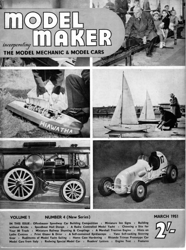
| incorporating THE MODEL MECHANIC & VOLUME 1 NUMBER4 (New Series) IN THIS ISSUE: Offenhauser Speedway Car Building Competition : Miniature Inn Signs : Building without Bricks : Speedboat Hull Design : A Radio Controlled Model Yacht : Choosing a Site for Your 00 Track : Miniature Railway Shunting & Couplings : A Marshall Traction Engine : Hints on Lathe Centres : Print Glazer & Drier : A Self-contained Epidiascope : Vane Self-tacking Steering t Gear : Rudiments of Model Yacht Sailing : Home Case Hardening : Rhiando Trimax Prototype Car Model Cars from Italy : Redwing Special Model Car : Readers’ Letters : Engine Test : Features MARCH 1951 pl
The main frame consists of a piece of } in. wide channel brass which forms a strong foundation. The channel is filed at each end to take the tube bearings, leaving the sides to overlap the tubes, and the whole is then soldered thus forming a very strong bearing Although one or two vane gears were on the market, the price was considered to be prohibitive, and apart from the cost, there is a great deal of satisfaction to be obtained if one sees one’s own design at each end. It was considered necessary to overlap the tubes at each side as when the boat is self-tacking in a strong breeze there is a considerable amount of strain on the end bearings. The tube used for the performing satisfactorily. The whole gear is constructed of light brass and soft soldered. It has been used in very rough weather and all the joints have stood up to the strain. It is therefore not considered necessary to use silver solder. The gear illustrated, has not been plated, because it was originally intended as an experimental design, bearings is of very light brass and was originally intended for aeromodelling. The vane tiller consists of brass rod, doubled over and fitted with a 6 B.A. bolt and nut as a driving pin, which engages the rudder tiller. The vane arm is 4g in. brass with a pin soldered at the end to engage the compensating arm, which is also made of but now that it has performed so well, it will no doubt, be chromium plated. Plating is well worth the extra cost, especially if the boat is to be used in salt VANE ae A.—Main SELF-TACKING LIST OF Body (channel STEERING PARTS GEAR brass in. square). O Aodieennn Arm (brass rod 1/Iéin. B.—End Bearings (brass tube to fit tin. rod). diam. threaded for weight—H). 0 yide). Arm (brass strip q/Iein. strip jin. wi E.—Quadrant of 1/32in. brass with 6BA soldered each end to take 6BA for adjusting length of tack). F.—Main nut bolts Quadrant (1I/Iéin. aie drilled all round the edge G.—Aluminium Discs |/léin. holes). (2 off for supporting vane with 6BA bolt passing through). H.—Lead Weight threaded for adjustment. l.—Brass spindles for vane arm and compensating arm (tin. brass). K.—Brass Pin 1!/léin. compensating arm diameter C when to en age self-tacking. L.—Brass Plate soldered on top of open channel and drilled to take tube O. M.—Brass Rod I/Iéin. diameter soldered to D and doubled to take vane. N.—Vane Tiller of I/léin. brass doubled and soldered to tube O. 6BA bolt and nut fitted in gap and movable. O.—Main Vane Bearing of brass tube with grat piece of tin. rod soldered in at its top: Main spindle of fin. brass fits in e—top of spindle formed to a point He made needle bearing. P.—Two I/léin. Brass Pins to engage in holes in main quadrant F. Q.—Main Base of jin. brass with main spindle threaded and soldered on. 202 be =e kind are required. to obtain plans in this country. qO-ene+ nee error owing to the fact that it was found impossible —” water. It will be seen from the plans that the gear is very simple to construct, and no special tools of any HE vane steering gear illustrated, was designed and constructed after a good deal of trial and
March 1951 a VE SELF TACKING STEERING GEAR etGea SON On the running left: before Pe MO ROR ES Vane equipped A Class Yachts the wind at Fleetwood, 1950. On the right: Start of a race between equipped craft—again at Fleetwood, 1950. vane Below: Steering Gear parts ready for assembly. Right centre: Gear fixed for heading. Bottom : Gear fixed for self-tacking. zs in. brass rod and doubled over like the vane tiller, and threaded to take the compensating weight. The vane arm is tapped 6 B.A. and fitted with a 6 B.A. bolt. When this bolt is unscrewed the vane “breaks’’, and is then in the self-tacking position. For reaching and running, the two arms are brought into alignment, and the 6 B.A. bolt screwed down to retain them in that position. The small quadrant soldered to the top of the rear bearing tube, has its edges turned up and cut out to hold a 6 B.A. nut, the latter being soldered in each side. The bolts fitted in these nuts can be separately adjusted so that the distance of travel of the vane feather can be controlled when self-tacking. The boat can then be made to travel on a long or short tack as required, and then come about. The tiller arm has a sliding 6 B.A. bolt so that the pressure exerted on the tiller can be controlled. By sliding the bolt to the extreme end of the tiller the length of the vane tiller is increased, and the length of the rudder tiller correspondingly decreased. This has the effect of quick action, but needs more wind pressure. By sliding the bolt in the opposite direction the reverse effect is obtained, the vane action will be slower but more effective in light winds. (Continued on page 245) 203 : iI) |
HT MODEL MAKER A Radio-Controlled “A” Class BY: GEORGE HONNEST-REDLICH .aS one of the leading experts in the development of radio control for models in this country, and author of the only book on the subject in English, G.H.-R, has now bravely invaded the world of sail—though frankly admitting his ignorance of the finer points. After the Fleetwood Regatta the below yacht manoeuvres crowd, and, as the on requested finally, took he pool, by part demonstrated carrying out of the members in a Frankenstein. The modern model yachtsman, like his full-sized counterpart, has traditionally disdained electronic or mechanical aids, with the exception of the various types of “Braine” and other gear to counteract fickle winds. It appeared to me that here especially a type of remote control which would be able to give a “personal” touch would be invaluable. For even a general straight course, the means of adjustment of trim of sail as well as rudder variation would require a new type of skill in model yachting. The obvious conclusion of complete control would in fact put the operator “on board” his model. My original experiments were made with a commercial 36 in. sailing boat of normal design, in order to gain alittle experience in this for me, new hobby. As only a “positional” rudder control was fitted, little was expected in exact manoeuvrability. However, the results challenge match against an expert skipper sailing in the In this match his chal- conventional manner. lenger beat him by a yard over two boards, making up over seven yards that he had lost on the up wind run by a recovery. really fast down wind Competent judges were of the opinion that, given craft of approximately equal speed, skippered by equally skilful yachtsmen, the radio controlled model would usually win. Of particu- lar interest on this occasion was the enthusiasm of reputedly diehard oldtimers to new slant on an established hobby. try out ADIO control is fast becoming a very necessary addition, or even the raison detre of every working model which by virtue of motion when launched is out of touch with the hand which created it. However, it is generally marked that the more mechanical a model is, the more the owner turns to radio control to give him power over his out-of-reach this We certainly hope the author’s plea for a ‘‘bit of competition” this summer will be answered. were to me astonishing, and after a few weeks’ practice I equip an G. decided to “A” class – Redlich —_Honnest demonstrates his radio control equipment on dry land—a_ picture taken at one of the larger model _ exhibitions. (‘Sport & General’ Photo.) 212
March 1951 Model Yacht racing yacht with both a progressive rudder control as well as a means of adjusting the sail position. (I must here apologise for my lack of correct yachting terms. I am the type who likes to learn from my own experience and then later get the correct phraseology. Before getting down to the constructional details, I studied the requirements. It was apparent that a progressive fractional “inching” of the rudder was more important than the necessity to achieve a sudden complete reversal of position. Therefore it was decided that the gearing of the rudder electric motor drive should be very low, giving the possibil ity of Close-up of the totally enclosed radio-control box let into decking of the yacht. In spite of trials in appalling weather ‘’the works” were movements as small as 5 deg., and allowing about 3 secs. for a complete change of helm from full port to starboard. never affected by water penetration, smaller 36in. commercial model. The sail was the major problem. The wind pres- sure on an “A” class mainsail even tery via an electric motor. In both motor and batter- or on the unit box is therefore definitely worthwhile. The transmitter controls were the next problem. A telephone-type switch lever was chosen for the rudder control. This was self-centring when released , and a quick flick in either direction enabled me to close hauled, reaching, and running posi- tions. Intermediate positions with this method were “inch” the rudder easily. The sail positions were chosen by a push-button, and due to the self-swi tching system used for the sails, the button could be not obtainable. The reason for this method was due to the fact that I intended to instal an existing radio receiver which had provision for only three “channels”. One being used for rudder port, and one for starboard, left only one for the sail control. A four channel radio would allow the sail to be progressively altered without recourse to a fixed positional sequence method. pressed quickly and then one could return to the rudder control without waiting for the sail to come to its final position first. This is very importa nt, because I find that during complicated manoeu vres one tends to over-steer and over-correct. Unless one’s hand is constantly on the rudder lever, the boat, for example after coming about, proceeds in a wavy line A self- before setfling on its new course. You will see by this very rough genera l description contained unit which could be lifted out of the hull solved both the accessibility and transport problem. The hatch was enlarged to take a watertight drop-in that radio control applied to model yachti ng is not just another modern device aimed at makin g it easier but it actually requires a greater and new type of skill to operate. Herein, in my opinio n, lies its very box of about 12 in. x 8 in. x 5 in. In this box the complete radio receiver, servo gear and all batteries were housed. Externally, through watertight slots protruded two levers for rudder and sail control. The former was connected to the helm. with a stiff rod. The sheets were operated via a movement doublin g block and tackle and could be hooked on to the second lever in holes at various heights in order to give the experimentally determined angle of sail required. In practice I found that I personally had yacht several times after long runs. The separate watertight I therefore chose a motor driven chain of gears which .incorporated an automatic switch of simple design, arranged so that short impulses from the transmitter would give three sail positions in se- the next problem. this movement. A push-button on-off switch for the com- les, power equals weight and size, and I had no wish to add unwanted weight to my boat. The installation was on plete equipment also protruded from the box, and finally about 3 ft. of aerial wire which was run up along the mast. In a full season’s use in all weathers, the complete job has not suffered from the effects of water either salt or fresh, whereas the hull has had to be emptied in a medium wind is very considerable, and the motive power to haul it in had to come from a reasonably sized bat- quence: either attraction. And now I make my appeal. This, as far as I know, is the only yacht of its type equipped with comprehensive radio control. Its popularity will lie in its means for real competitio n of sailing skill. I . cannot compete with mysel f. It is up to you to pro- more control over the yacht by mainsail control alone (in combination with the rudder of course), but provision was also made for connecting the jib to this lever at a lower hole position to give a smalle r angular 213 duce other radio control “A” class yachts or even “D” raters, so that either demon strations or competitions can be held. From the moment the first few exist, the general interest will incre ase by leaps and bounds, and I prophesy that a new era of model yachting in both design and skill will be born.
AA MODEL MAKER The Rudiments of Model SHIPWRIGHT GIVES SOME PONDSIDE ADVICE N the short space at my disposal I can only touch upon the rudiments of model yacht sailing. I hope, however, this short dissertation will enable the beginner to grasp the main principles and thus enable him to enjoy the fruits of his building efforts. Some model yachtsmen achieve success right away, others learn the hard way. I strongly advocate the joining of a model yacht club, if there is one in the district, for it is here he will find willing help and advice which will soon enable him to become profficient enough to enter his model in club competitions. BEATING.—In the first place it must be clearly understood that no yacht can sail into the wind’s eye. The average well designed model will point as high as 4 points off the wind. As each point is equal to 114 deg. it will be seen that the nearest the bows can point to the wind is 45 degrees. This is known as beating and under these conditions the yacht sails by the trim of her sails only. The quadrant steering lines are slacked off and the beating sheet attached to the main horse. The average beginner always makes the mistake of trying to point the model too high, ie. sail closer to the wind than is possible by tightening the sheets too much. The result is that the yacht takes on an Top right pictuFes demonstrate ‘’Running with spinnaker set”. excessive heel and looses speed. Sail as upright as you can; always remembering to slack off the jib sheet slightly more than the main sheet. Fig. 28 illustrates a typical example of a beat to windward showing the direction of the wind, the direction of the yacht’s head and the trim of the sails. A few moments experimental sailing will teach the novice far more than pages of explanatory matter. REACHING.—When the wind is abeam, or a little forward or a little aft of it, the boat is said to be on a reach. The beating sheet is unhooked and the steering lines attached to quadrant. It will be seen that the sail pulls upon the weather sheet as the steering lines are crossed. Hook the weather line two or three holes from the centre of the quadrant and slack off the tension cord. Now point the bows in the direction you wish to sail and slack off the sheet by means of the bowser until the wind spills from the sails. Then haul in the sheet slightly and try her out. Again, experience will be required before the best results are obtained, but if you can enlist the help of an old hand so much the better. As the wind comes further abaft the beam sO must the sheets be eased off until the jib fails to do its work owing to its being blanked by the main sail. When this stage has been reached it is time to set Below left first three pictures show ‘’Beating into wind’’. below depict “Reaching”. 214 Remaining two pictures
Yacht Sailing eT HE NOVICE SK PPPER the spinnaker, and this point of sailing is known as:— RUNNING.—Until the wind hauls right aft the spinnaker should be set well forward, i.e. the boom pointing forward. As the wind comes further aft ease the mainsail and haul the spinnaker aft. Finally, as the wind comes dead astern the mainsail is eased right off as square as possible, but not far enough to foul the shrouds and make the steering inoperative. TUNING-UP.—No model yacht can be expected to put up her best performance the first time she is put into the water. The beginner is strongly advised to enlist the help of an experienced model yachtsman to assist in the process of tuning-up. This process is a question of perfect balance between the sails and the position of the mast—hence the use of a mast slide to move the centre-of-effort in a fore and aft direction. Let us assume that we are about to launch our boat on her trial trip. Her sails should have been stretched by a preliminary run without bothering about the finer points of sailing. The test is to be sailing to windward, i.e. beating. These pictures were specially arranged for “Model Maker” and feature champion Marblehead in action. Set course 4 points off the wind with the mainsail close hauled and the jib nearly so, but not too tight. Now watch! If she refuses to sail properly to windward or falls off the whole sail plain is too far forward. Move it aft by means of the slide and try again. She may now go into “irons”, i.e. run up into the wind and stay there, perhaps moving backwards, with sails swinging. In this case move the mast forward. When the correct position has once been found it will be correct for all time. Mast rake may also be necessary, but this is purely a matter of experiment. When a model yacht has been Mr. Arthur Mullett’s correctly tuned up for windward work she will sail full-and-bye for as long as she is on that course, never slowing or altering course. ae OF rage ej WIND OlIAGRAMMATIC OF A YACHT HAULEOD PORT 215 eS OS ON VIEW CLOSE THE TACK. eat
March 1951 Hints on Lathe Centres TF good accurate turning is to be expected where work is done between lathe centres, a few important points must be remembered. The centre indicated by A in the accompanying illustrations is in sound condition with its point intact. In view B, however, the centre is shown with its point completely burred over, and accurate work becomes difficult with a centre in this condition. Moreover, the centre in B is often the cause of work flying out of the lathe when cuts are applied, since the bearing is reduced to a very weak condition. Lathe centres when not in use should be carefully placed in the rack; if simply dropped down in any odd spot the tips can easily become damaged. Many centres are given a final tap home with a hammer, and this is the cause of many points becoming blunted. Any adjustments of centres should be made with using a piece of hard wood between the point and hammer, or by using a skin hide hammer. Many lathe centres quickly become burred-up at the tip due to the poppet centre tip becoming overheated during the work revolving. It is most important to see that the poppet centre is carefully lubri- cated in order to prevent burred-up tips as in B. It is little use lubricating a badly made centre bearing in a piece of work, however, since it is readily seen in view C. The point of the centre is forced on to the bearing, and much friction, with resultant heat, quickly takes place, with burring-up at the tip. First drill the ends of the work, and then form a good centre bearing with the square cutting centre in the poppet end as shown in view D. The square centre is adjusted for cutting by putting a little pressure on the tailstock wheel, and use a little oil for lubricant. The small hole in the end of the work should be deep enough to allow for cutting a good bearing VANE STEERING GEAR without taking the drill hole completely away. The square cutting centre should be removed from the poppet as soon as the work is done, and the ordinary centre replaced. The work is thus provided with well-formed bearings for the lathe centres to seat in, and a glance at view E illustrates the point. Here it will be seen, the tips of the centres are free in the drill holes, which is a vast improvement on the badly made bearing in C. Before commencing work the bearings should be packed with grease or graphite. (Continued from page 203) It is hoped to contribute another article on sailing with a vane gear. Different boats require different settings, but it is most interesting trying out a boat with a vane gear. Any adjustments made to the vane setting show up immediately in the boat’s behaviour. The Braine gear was undoubtedly a great step forward in the methods of steering model yachts, but when one realises that the gear was originally invented in 1904 and that it has been in general use, practically without modification, to the present day, it is apparent that the time has come for a further step forward in this direction. In my opinion the vane gear is a very great improvement and definitely more positive in action. Having used a Braine gear for several years it took a long time to convince me that the new idea was better, but after one race with the vane gear, it was decided that the time had come to change over. Friction on the main spindle (and the rudder) should be reduced to a minimum. The top of the main spindle is, therefore, ground to a fine point and rests against a piece of-4 in. brass soldered into the top of the main bearing tube, thus forming a needle point bearing. Quick adjustment, vital in any race, is obtained by lifting the main body of the gear so that the engaging pin is clear of the holes in the main. quadrant. The vane can then be moved to any desired angle and simply dropped back into position so that the pin again engages the main quadrant. The other pin fitted to the main body, is used when running before the wind when the main body is turned through 180 deg. to bring the vane feather inboard. The vane feather is made of 4 in. balsa wood and varnished. To be effective the area of the feather should be five times that of the rudder. 245


