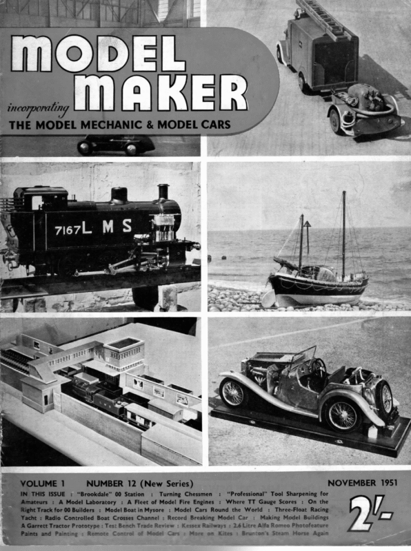
- A Three-Float Racing Yacht. By A. M. Colbridge

) El rel NOVEMBER 1951 NUMBER 12 (New Series) THIS ISSUE : “Brookdale” 00 Station : Turning Chessmen : A Model Laboratory : A Fleet of Mode! Fire Engines : “Professional” Tool Sharpening for : Where TT Gauge Scores ‘rack for 00 Builders : Model Boat inMysore : Model Cars Round the World – : Radio Controlled Boat Crosses Channel : Record Breaking Model Car : : On the : Three-Float Racing Making Model Buildings A Garrett Tractor Prototype : Test Bench Trade Review : Kessex Railways : 2.6 Litre Alfa Romeo Photofeature and Painting : Remote Control of Model Cars : More on Kites : Brunton’s Steam Horse Again
November 1951 A Three Float Racing Yacht BY A. M. COLBRIDGE THE original catamaran layout, comprising a main hull with a single outrigged float, possesses con- siderable stability. Although not recognised as a racing type, yachts of this type are capable of ex- tremely good speeds, particularly in very light winds. The catamaran layout, developed into a true twinhull craft, is excellent for power boats, both model and full-size. Most modern power boats do, in fact, approximate to this form of suspension at high speeds, where the hull is actually skimming the water on three (usually) or four small planing surfaces. Apart from low skin resistance, the added stability achieved by a broad (virtual) beam is considerable. The same remarks as regards stability apply to sailing craft design but the true catamaran, being asymmetric in layout, has certain limitations on this score. The same principle, however, has been extended to the trimaran or three-float sailing craft, consisting basically of a central hull with two outrigged floats, one on each side and equally spaced from the centre line. Being a symmetrical layout it can have a performance and maneouvrability fac- tor equivalent to that of a single-hull vessel. The trimaran has been tried out in full-scale practice in America and is characterised by its ability to achieve very high speeds in light winds. Under such conditions it is considerably faster than a comparable conventional yacht. Largely this is because the layout does not permit the yacht to assume a large angle of heel, hence the sails are more truly vertical under sailing conditions, and thus offer more effective area to the wind. In other words, since the vessel is not free to heel over to any marked degree, the effect is equivalent to an increase in effective sail area. It was with these thoughts in mind that a model trimaran was contemplated. It was considered that most of the full-scale details could be retained with small modifications and the result should be a stable very fast sailing craft under light wind conditions. In rough weather it might get into difficulties, unless sailed under considerably reduced area. Initial tests were made with a half-size model with solid balsa hull and floats which more than proved the contemplated layout. Stability was such that even in rough conditions it could usually fight its way out of trouble and would appear to retain the A wingsail catamaran model shown at the Britain Can Make It Exhibijion in 1946, designed by Messrs. Wells Coates, O.B.E., R.D.I., F.R.1.B.A., It was B.A., B.Sc., Ph.D., and Leslie Appleton, M.A., A.F.R.Ae.S. built primarily to develop the wingsail but is’ an excellent example of modern scientific handling of one of the oldest boat forms. 741
MODEL MAKER i Bae STRUTS , Yo ans” FIG. 1 GENERAL ARRANGEMENT sae } | & eye~ -| MAST Wax 4” va DRAWING i STRUT re $s | ifu 2 ICKING€ J | —— 5 HULL Jo” \ ee ee high speed characteristics of its full-size prototype. The larger model, with simplified construction, is certainly an interesting project for anyone interested in sailing models to attempt, for it is essentially a modern design which, we feel, is capable of still rectangular in shape and dimensions can be found by reference to the hull plan and elevation. Former No. 4 has a + in. slot, 1 in. deep in the middle of further development. The general layout is given in the main drawing, from which the main dimensions can be found. The major construction features will now be described in detail, starting with the main hull. Hull dimensions are detailed in Fig. 2. FIG. 2 Mark out a deck and bottom to the offsets given in. ply, and cut out. Note the 2 in: x + in. the deck for the mast and the 7{ in. x + in. in the for the keelboard. All the formers ie cut from } in. sheet material, balsa being a good, light medium and easy to work. Each former is 742
November 1951 the bottom side to admit the keelboard. All formers have x in. square notches cut out of each corner. Pin down the ply bottom panel on to a flat surface, with the extreme bow blocked up 4 in., as shown in Fig. 3. Add a similar 4 in. dia. block under the stem. Other packing blocks can be added under the fore part to achieve the required curvature, if desired. All the formers are then glued or cemented in place and shaped bow and stern blocks added. An open box is built up between formers 3 and 4 with + in. sheet balsa, leaving a slot + in. wide, as shown in the diagram. locate the keelboard. This box will eventually The next stage consists of pinning and glueing the deck panel in place over the assembly, as in Fig. 3. Check that it beds down accurately on top of each former and make sure that each glued joint is a good one. A slow drying cellulose cement is probably the best type of glue to use. Only a waterproof glue should be used, in any case. Spruce strips + in. sq. are then added under the deck and bottom panels, fitting in the notches in the formers. A 1 in. x % in. hardwood block is notched as shown and glued under the deck against former 5, and the assembly can then be cleaned up. Sides cut from -; in, ply can then be pinned and glued in place. This completes the basic hull assembly. The keelboard is cut from 4 in. ply to the dimensions shown in Fig. 5, with a cut-out, as indicated, which will locate the mast. Assemble the keelboard in the hull bottom slot temporarily, as a check, but do not glue in place yet. Float construction follows similar lines, but is very much simpler. The lower or planing surfaces of the floats are chamfered off at an angle of 10 deg., which is produced by cutting the former to this chamfer. First mark out and cut the deck plan in } in. sheet balsa. Use this as a pattern to cut out an identical panel from } in. sheet balsa for the bottom. All the formers are % in. deep at their widest side, with one edge tapering off as shown in Fig. 7. They should be cut from } in. balsa and trimmed to exact width by reference to the cut-out deck or bottom. Lay the 4 in. deck on a flat surface and cement the formers in place, also the shaped nose and bow blocks, as with the main hull. The only difference ~ SS FIG. 6 oS HULL FORMER pa. DECK FROM U2″ BALSA ia BOTTOM FROM Genet a ‘ae eS ee OG BT Pe it 6 I NE SLOTS I II —, “{ | ane 1/8°BALSA ai ysis” is that the floats are built upside down (see Fig. 8). Cement the 4 in. sheet bottom in_ place, and then trim off the formers vertical. The js in. balsa sides can. then be cemented in When place. set, | if paass SHEET this at this stage. With the two floats and hull complete the model can be assembled. Prepare the hull by cutting a { in. x 7% in. notch as shown in Fig. 9, this coinciding with the cross member adjacent to former 5. The rudder fitting can also be screwed to the stern block at this stage. This consists of a length of brass tube soldered to a piece of shaped brass, which is then attached to the stern block with woodscrews. The tube should be 2 in. long with the bottom of the tube flush with the bottom of the hull. This allows x in. of tube to project above the deck level and carry the rudder quadrant well clear of the deck. Hull and float assembly is shown in Fig. 10. The struts are simply 17 in. lengths of ? in. x + in. spruce or similar straight-grained hardwood, glueing in slots in the hull and floats. To give the required float angle of 10 deg. the front strut comes above the deck level of the main hull and is actually attached by means of packing glued between the strut and the hull. This stage should be tackled with care. Block the hull up so that the design load water line is parallel with the table top and adjust the floats until they have the required angle. Then firmly glue and pin the appropriate amount of packing in place. Leave the assembly ample time to set thoroughly before disturbing. % 743 i away ability, cover each float completely with thin silk. This, when doped or painted, will result in an extremely strong assembly which is not readily damaged or dented. The floats will come in for a certain amount of abuse when the model is sailed, so make allowances for 74 II carve the aft portion of the + in. deck to conform to the side elevation shape, and finish each float by sanding down smooth. Cut the two notches in the deck to take the struts and then, for dur-
MAST 36% 4% Ya” FIG. ] Sixes Seen 12 FIG, 13 mg savor After this you waterproof and finish the hull and floats in any colour required, prior to adding the fittings and the rigging. The keelboard can now be _— glued securely in place, forming a fillet of glue along the entry line into the slot. The keelboard must be a close fit, otherwise the hull will leak. Pack out the slot to be thoroughly __watertight, if necescan Piet rSe boon P The — simple Braine-type rud- der gear is shown in Fig 11. FIG. The brass wire rudder spindle soldered to 14 the top of the quadrant. This spindle passes through the rudder tube and the brass rudder is soldered to the lower end. The rudder projects beyond the stern and is in a somewhat vulnerable position—a point to remember in subsequent handling. The mast is cut from a 36 in. length of good, hard, straight-grained stock. The first 3 in. is parallel, after which it tapers in width to % in. at the top. Round off all edges on the tapered portion with sandpaper. The mast fits through the deck slot and down into the slot in the top of the keelboard. It is prevented from moving sideways by the false formers cemented in the hull. Booms can be cut from suit- MODELMAKER’S Model Signal Operation MIXTURE. . able dowelling, or dural tubing. The latter is particularly favoured by some modellers. It is not proposed to describe the rigging in detail, as this follows standard practice, and is kept as simple as possible. The deck plan of Fig. 14 shows the main rigging points. The jib should be provided with a horse, and it is an advantage also to have a horse for the mainsail so that the yacht can be sailed without the rudder gear in operation, if desired. Sail patterns can be derived from the dimensions given in Fig. 13. Mark and cut out as paper patterns. Model sailcloth is really the only suitable material for sails, and when these are cut out, allow the necessary extra strips for the hems. The model is sailed and adjusted on the same principles as any other yacht, except that it is less responsive to rudder and so considerably more rudder power can be used on the automatic steering gear. Best performance will only come by proper balancing, which is achieved in the first instance by adding lead ballast weights to the bottom of the keelboard to float the hull on the load water line position shown on the main drawing. If it is found desirable to add more ballast, this is quite in order, as long as the same attitude relative to the water line is maintained. In the drawn position, the extreme aft tips of each float just touch the water. It does not matter greatly if a greater draught has to be employed and more of these floats submerge when floating stationary. No specific recommendations for the actual amount of ballast required can be given since this will vary with the overall weight of the model. Different materials and different constructional technique cause this to vary considerably from one model to another. Another tip to remember is that with models of this type it is sometimes an advantage to ballast the stern down. This is particularly advantageous for running downwind. Try this if your boat tends to “dig in” rather than plane smoothly forwards, but otherwise stick to the recommended waterline position. e sk D. F. T. Roberts points out a printer’s error in his article on this subject in the September issue of Model Maker. The type of second-hand Post Office relay that should be obtained is 1,000 (one thousand) ohms. variety and not 100 (one hundred) as stated. He goes on to add: “I know it sounds a lot, but it works, and you can see it then makes sense. The particular danger in the error is that P.O. stuff is nominally 25/50 v., not 12, and someone may think that the intention is 50 v. 1000 w = 12 v. 100 w. The 1,000 w. is intended to be used with 12 v. working NOT 25 or 50: it will even work sometimes on 6 v.! 744 e e e It did not occur to me that any voltage other than 12 was intended, but the use of P.O. stuff may cause some people to think that 25/50 v. is meant. The whole point of the article was that closed magnetic circuits multiply the force obtained by about five to one hundred times—which the 1,000 ohms. shows in no uncertain fashion. Pesters for 4mm. Trackside Hoardings Messrs. ERG (Bournemouth) Ltd., have drawn our attention to a printer’s error in our September review of their new Will’s Trackside Posters. The set which is available at 1/104d. including P.T_ comprises three sheets each containing six different posters in full colours, not five as stated.


