- Model Yacht Club Notes. By “Commodore”
- Vane Gear Commentary. By A. Wilcock
- Halceyon A New 10-Rater. By John A. Lewis (Plan available in the US VMYG Store)
- Tuning Up a Model Yacht. By W.J. Daniels

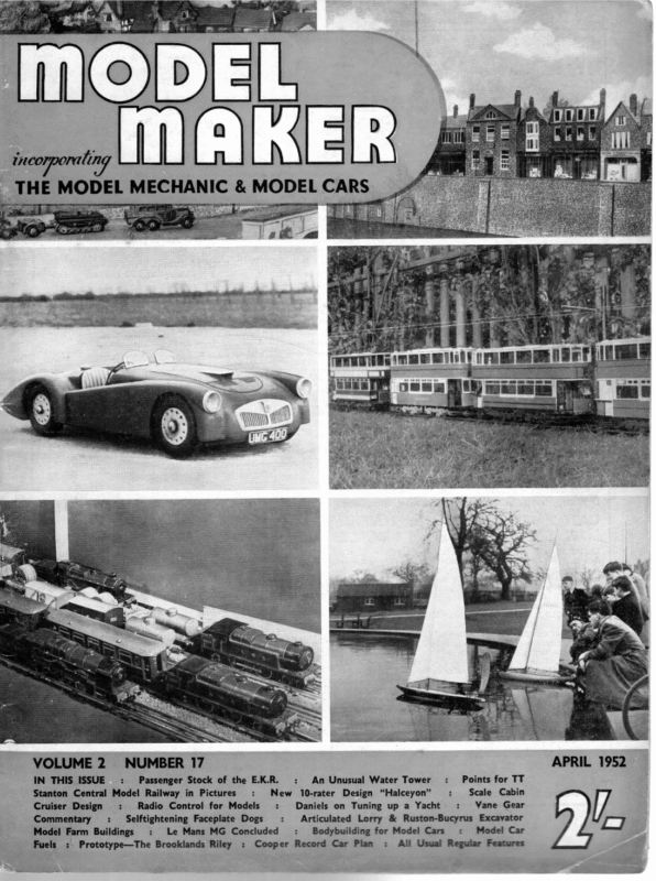
__THE tneopporaling A K MODEL MECHANIC & MODEL CARS NUMBER 17 VOLUME 2 IN THIS ISSUE : APRIL 1952 Passenger Stock of the E.K.R. Stanton Central Model Railway in Pictures : New Cruiser Design : Radio Control for Models +: Commentary =: _ Selftightening Faceplate Dogs : Model Farm Buildings : Le Mans MG Concluded Fuels :. Prototype—The Brooklands Riley : : An Unusual Water Tower Points for TT Scale Cabin 10-rater Design “Halceyon” Vane Gear Daniels on Tuning up a Yacht Articulated Lorry & Ruston-Bucyrus Excavator Model Car =: Bodybuilding for Model Cars Cooper Record Car Plan All Usual Regular Features
April 1952 WE are pleased to report the receipt of several club fixture lists, and hope that all clubs will oblige during the next few weeks. We cannot, of MODEL course, publish these lists in our columns for considerations of space alone, but their possession will often enable us to pay a casual visit to club waters YACHT when something is ‘‘on’’—an opportunity that might otherwise have been missed. We were recently in Bournville to take pictures of our new 10-rater de- CLUD \OTES sign Halceyon, from the able board of John A. Lewis, who is, incidentally, Official Measurer for the Midlands, and enjoyed a very pleasant afternoon— though wind non-existent—at Valley Parkway Pool, and here captured our heading picture of M.Y.A. Racing Secretary “Mac” Fairbrother with his trusty 36 in. Restricted Mickey. This boat, built before the war to a design of the late W. H. Davey by S. C. Langford, has been putting some more modern craft to shame in Mac’s able hands. Last year in five outings it picked up four trophies and a second. Mac is almost willing to match it against all-comers, but for the existence of one “dark horse’’ right in BY | COMMODORE the club boathouse . . . but, bar one… . Y.M. 6-m Owners’ Association Hon. Secretary N. D. Hatfield provides us with a list of this club’s Open Race Fixtures for 1952, to All be held at the Rick Pond, Hampton Court. events start at 10.30 a.m. May 11th: The Metropolitan and Southern District A Class Championship. Three boats per club; 10/- per boat. (Closing date of entry, April 18th.) July 6th: Glenham Cup. Three boats per club; 5/per boat. Sept. 7th: Serpentine Cup. Three boats per club: Oct. Sth: Gosnell Trophy. Three boats per club: 5/- per boat. 5/- per boat. This should give 6-m enthusiasts plenty of scope for their activities, and prove that the Southern fol- lowers can provide just as exciting racing in this class as the more numerous following over the border in Scotland. Bournville M.Y. & P.B.C. Whit Monday, June 2nd, will see the 28th Annuai Whitsuntide Regatta on the Valley Parkway Pool ai Bournville, together with a National Power Boat Competition and Display. Power Boat secretaries are urged to get in touch with Hon. Secretary M. Fairbrother, sending particulars of number of boats in 30, 15 and 10 c.c., hydroplanes, and prototypes of all classes for steering contests. Catering will be by the Civic Authority, and will be assisted by stating numbers of visitors and supporters accompanying competitors. Start is at 10.30 a.m. Bournville Club Sailing events will be arranged for Saturday, May 31st. M.Y.A. Open ‘Championship M. Class This event will be contested on Birmingham’s rr Sailing Water at Witton Lakes, Erdington, on May 31st, June Ist, 2nd and 3rd (last date of entry May 3rd). As the first of the season’s National Open events it should provide an excellent holiday outing for all enthusiasts whether or not they are skilful enough—or fortunate enough—to be actually competing. As there is also a good programme at near- by Bournville, it might be a wonderful opportunity to have an “‘all boats’? Whitsun, covering the M Class start on Saturday and Sunday, then nipping across the city to the Power Boats on Whit Monday, and back to Erdington for the last Marblehead day on June 3rd._I understand it is about twenty miles by the Ring Road round Birmingham between these two venues. This double coverage is—at any rate— what Model Maker proposes to attempt, so please organisers arrange for “sensations’’ to be neatly staggered ! To All Model Yacht & Power Boat Clubs Hon. Secretaries and/or Publicity Secretaries are once again reminded that we want to hear from them. Notes for inclusion should be in our hands by the lst of the month previous to date of desired issue.
MODEL MAKER VANE GEAR BY A. WILCOCK WELL-KNOW!) the combination giving a high pointing course which is sailed at speed. Sail plan setting is then the starting point for the most efficient trim. The recognised method is: — 1. First wait for a day with only a light breeze (this is important as many boats that will readily FIG, 1] sane =” – eee al el —— ies: 5 peas es eS eee GINCE the last war the revival of model yachting “has seen the vane steering gear adopted almost universally in all classes but the 36 in. restricted. (This class presents physical difficulties otherwise the adoption would no doubt have been truly universal.) That this is so is the best recommendation that the gear could have. So far as the writer is aware, literature on the gear is scanty, and what has been written is not now readily available. The gear has its own characteristics and technical problems. To the critical ob- server it is apparent that these are not understood by many skippers who consistently use the gear, and it is for this reason that the following notes have been written. The first characteristic of the gear, which has no doubt led to its exceptionally rapid adoption, is that a good or bad boat fitted with vane gear steering adjusted to approximately the right position and the sheets also adjusted to approximately the ideal position will “make the course” and at not a bad speed. This is very encouraging to the novice and as it were, puts him in the running from the start. is good for the sport. This Fortunately, again for the sport, to get the most out of the boat and gear is a tricky business, and one in which the combination of a good boat, skipper and gear all working in har- that better understanding of the operation of the x vane steering gears, in order of importance are: — 1. Freedom of movement of all moving parts. 2. Balance of the parts individually or in appro- priate combinations. 3. Precision of adjustment. latively little power and it is most important to use it for moving the rudder against water pressure only. This question of freedom of movement is mainly a While approximate sheet and gear adjustments give a course, it cannot be too strongly stressed that speed and ability to “point” are obtained only by meticulous attention to precise adjustments giving a harmonious action between the parts and steering on the intended-course. It is generally accepted that 4 ing as a whole that those with non-tack vanes will find much to the point. The three essentials to good performance with steering where the whole power of the main sail is available to overcome friction and any stiffness (however undesirable even in that case) the vane has re- gear that will gain the points on the lake. a ments will therefore primarily relate to self-tacking vanes, so much, however, is applicable to vane steer- Regarding (1) with vane steering, unlike Braine mony should come out on top. It is the purpose then of these notes to try to give some “‘clues”’ to : point with a fresh breeze are reluctant to do so in lighter airs). 2. Unship the gear and centre the rudder carefully either by stops or a taut centring line. 3. With the jib and main sheets fairly close hauled, such that the main and jib booms make equal angles to the centre line of the boat, and the kicking strap slack, adjust the mast position, remembering to maintain the rake by adjustment of the fore and back stays, until the boat will consistently just come into irons, i.e., point into the wind with the sails flapping. It is worthwhile checking that the right position has been obtained by moving the mast + in. forward when she should sail steadily once again on a course 30 deg. or so off the wind. Move the mast back to the position found. Patience in finding the correct position will be amply rewarded by the performance later obtained. The gear may now be reshipped and attention paid to gear adjustment detailed below. For serious racing and in particular to M.Y.A. rules, a self-tacking vane is a necessity. The com- mechanical one both of design and execution, and with the Editor’s permission may well be the subject of a further article. The immediate points to look at with what you already have are (a) freedom of the rudder on its pintles or bearings; (b) freedo m of the rudder stock in its tube, particularly from any a small degree of weather helm—that is rudder to leeward—-when point high is ideal. In order that this weather helm shall not steer the boat off course stickiness brought about by paint or varnish; (c) lack of binding in the linkage between the rudder the sails must be set to bring the boat into the wind. 286
OMMENTARY IN SOUTHERN MODEL CIR CEES and gear whatever its type may be, gears, pin and slot or push-pull bar; (d) freedom of the vane on its pintle; (e) freedom of the self-tacking parts of the vane on their pintles or bearings, and the self- tack link, usually of the pin and slot or gear arrangement as for the rudder linkage. Having dealt with these matters, attention can now be directed to ‘“‘balance’”’. In the author’s opinion balance is the least understood and therefore most neglected aspect of vane gear application, while it affects performance most in getting that last ounce out of a boat in racing, and should therefore receive more thought and attention from all skippers. Balancing starts with the rudder and its linkage to the vane “base” without the vane superstructure. The aim is to counter-balance the tiller or linkage so that with the hull in the water and no centring line on the mechanism the rudder remains central when the hull is heeled to port or starboard. It is neces- sary to adjust the counter-weight with the rudder submerged as depending upon its material and con- struction it may have buoyancy. The vane superstructure should be balanced separately in two ways about the point of attachment to the vane base. This can be done by using a temporary rod or tube on which the vane superstructure can be mounted for balancing. The need here is for the superstructure to balance with the vane fixed relative its counter- weight as shown in Fig. 1 for a typical mechanism. Balance is shown by the mechanism staying in any position of a revolution in which it is placed. Possible corrections to achieve this are given below. The second requirement is for the mechanism in the selftack adjustment, i.e., unlocked, to take up equal angles to the base bar which should remain horizontal as shown in Fig. 2. In the simplest and most usual form of gear the vane and counterweight are mounted on pintles set at equal distances from the mounting hole and for the balances previously described the counterweight and its mounting should equal in weight the vane feather and its mounting. When in position on the bar the counterweight can then be adjusted by moving nearer or farther away from its pintle until the assembly balances, and it should be found that balance is achieved in either of the tests given. The vane feather must, during this process, be set at its normal vertical or nearvertical position. Changes in its angle will affect balance. A common failing is to change the feather for one of different weight and altering only the position of the counterweight, this can correct bal- ance in only one of the tests, unbalance must occur in the other. As previously mentioned, balance is upset by altering the angle of the feather. This is bad practice, but nevertheless expert skippers fre- quently do this although usually only on the run where balance does not matter a great deal because there is little heeling. On other points of sailing it is very inadvisable. The effect of balance troubles are to be noticed when a change of wind strength leading to variations in the angle of heel takes place without a change of wind direction. Under these conditions out of bal- ance may cause the boat to point higher or fall away depending in which direction the gear is out of balance. The foulings may easily be blamed on the sail plan, angle of rake of the mast, or sail setting or hull shape, in fact almost anything but the vane gear, which may well be the cause under these conditions. While quoting the most usual vane gear assembly to illustrate balance, it is one that is most readily balanced, and this probably accounts for its popularity. Some designs are inherently impossible perfectly to balance, but discussion on the various arrangements is proper to a subsequent article. The third essential to vane gear performance is that of precision of adjustments. It must be admitted here that this is mainly a matter of experience, but it must first be appreciated that it does matter. When beating in particular, which is the course on which most points are obtained—a few degrees make all the difference. Here the course scale on most com- mercial gears is not very helpful, and something larger and more precise such as a celluloid school protractor will be found a great help. The aim is a sail setting that will point the boat just a little higher than the course required, and a vane setting that will give 3 deg. to 5 deg. of weatherhelm. This keeps the sails full and drawing without undue rudder drag and a fast course is sailed. The right vane and sail combinations exist for the other points of sailing and the same arguments hold. Not too much helm and not too little,.and the sails trimmed just as carefully as for Braine steering and away shoots the winner. 287 ———— — April 1952
mMmODEL MAKER THIS NEW DESIGN BY JOHN A. LEWIS OFFERS ENTHUSIASTS AN OPPORTUNITY TO BUILD A FAST MODERN BOAT, DEVELOPED FROM A SERIES THAT HAVE ALWAYS PROVED ABLE TO HOLD THEIR OWN ON THEIR HOME WATERS, AND IN CAPABLE HANDS SHOULD BE WORTHY OF SAILING IN THE VERY BEST COMPANY. URING the next few months we shall be describing the building of a new 10-rater, and it would not be out of place to discuss firstly a few of the con-siderations which influenced the dimensions and hull shape of this particular design. It is very tempting when setting out to develop a 10-rater design, to go for something different from the usual run of things and to be original. The beginner should realise, however, that it is probably more difficult to be original in yacht design than anything else, as the building of sailing boats has been one of man’s occupations for many, many centuries, and all shapes and sizes have been tried out. Wind and water do not change. The biggest scope SHEET | OF 10 – RATER for originality lies in the choice of hull dimensions, not the shape, and in the development and application of aerodynamic theories to the sail plan. Let us consider a few of the factors which have to be carefully blended together when commencing a 10-rater design. The Hull As the rule SA | x LWL = 10 governs the sail 6000 area and waterline length the first decision has to be regarding the L.W.L. (load water line) length. It is well known that the longer a boat is on the L.W.L. then the faster is it capable of travelling through the water, but, with this rating rule the penalty of long 2, IO-RATER ‘HALCEYON’ DESIGNED FOR MODEL MAKER BY JOHN. A.LEWIS COPYRIGHT OF MODEL MAKER BILLINGTON RD. PLANS SERVICE. STANBRIDGE,NR. LEIGHTON BUZZARD. 20. a LWL. = 19. 6 T e re 7 Dw, 8B. Ces eee J AKAN PSL / 3 I TI 9. FULL SIZE. SPACING WATERLINE Bass —— SESS as aw 10. 2 | EE |2 Z Fm ere ——_ = re =!+ ss — el 7 9 | O._LEAD APPROX. 21-OLBS. i a 2. SJ —— | P ©G. OF LEAD IN LINE WITH CB. : 13 5 E /pf NOTE: GREATEST BEAM IS ON WL.3 & NOT aT ; A SECTIONS 6-14. _ LEVEL OWING TO SHOULD BE NOTED PARTICULARLY BETS =— oe ———a wr 3 ¥e [ 4 ¥. 2-6” 5 Ct LAG | z psezs J Sg44SG 78 H BODY_PLAN. 3 —— Lae Lats Oi | . fe) ——}———4 a ‘ U a \ =——— ONE HALF FULL SIZE. A | SS 2 cle SHEER AND WATERLINES 16.17 18.19 20. XY. ee 14.= {19 ay a gL SECTION 5 ue — [ 13.15. 17. < as I[ q 18 x. |}— — ae al = TUMBLE HOME & THis a Sea | pe cal :
April 1952 Halceyou L.W.L. is the reduction in sail area. The loss of sail area is particularly noticed in light winds because coupled to the smaller sails is the greater wetted surface area of the longer hull; this is assuming, of course, boats of normal shape and equal displacement. Much of this disadvantage may be offset by maintaining the hull in a very smooth and polished condition as the greatest resistance to forward motion at slow speeds is skin friction. The L.W.L. of 10-raters has increased steadily from 40 in. to 50 in. during the last 20 years. The longer boats are of more healthy shape, and the freak scow that the rule tended to produce has been dropped in favour of more consistent all-round per- LENGTH ON LW.L.*52-0_ INS. DISPLACEMENT _ = 30°61 _ LBS. WEIGHT OF LEAD = 21-OOLBS. SAIL AREA ALLOWED + 153-8 0.
Sivan formance. Having reached a length of 50 in. L.W.L. there seems to be hesitation on the part of designe rs in exceeding this figure by more than a couple of inches. Having designed and built a boat of 55 in. L.W.L., paying great attention to wetted surface reduction and a fine finish on the hull, I find that the light weather performance does seem to suffer to an extent, considerably greater when compared with a boat of 50 in. L.W.L. than does the L.W.L. boat when compared with one of L.W.L. However, if the average conditions which you sail your boat are of moderate to 50 in. 45 in. under strong breezes, then by all means have the 55 in. L.W.L. or even more. For general purposes a length on the water of 52 in. seems to strike a good compromise. Next we come to the question of choice of displacement, and there has been a good deal of argument between the “heavyweight” and the “lightweight”. As with all things in yacht design a compromise offers the best way out, and I have found from experience that a displacement of between 28 Ib. and 32 Ib. can provide good all-round qualities. It may be taken that 30 Ib. or over is tending towards the heavy end of the scale, and that 24 Ib. is about the lightest it would be desirable to go. The heavier boat need not be slow in light winds as it can be designed with an easy form of midship section giving low wetted surface and, of course, a heavier boat when once moving will continue to do so, due to its greater momentum, when the “flats” appear in the wind. The choice of displacement is made out of consideration of stability and closely related to this question is the shape of the midship section of the hull. Without delving into the theory of the subject it may be said that the shape of the hull section accounts for the initial stiffness up to say 15 deg. angle of heel, and from then on the pendulum of the lead ballast has the greater effect. I believe that it is difficult to achieve too much stability in a model provided that the period of rolling is not too short. In other words, make the hull as powerful as possible, but not such that when the wind pressure on the sails eases the model springs smartly to attention and shakes the wind out of the sails. Again we have to compromise, and the section shown on the new design is my idea of that which is desirable. To attempt to achieve the same stability with a boat of lighter displacement would mean that the beam would have to be increased, or the section made firmer, or the draught increased, or the ratio of ballast to displacement increased, or a combination of all four factors. It will be seen that beam of the boat is very closely related to the mid-section, displacement and stability considerations and it follows that the more powerful boat will tend to have the more beam. Generally speaking, it is better to keep the beam moderate and Typical dimensions of a modern 10-rater would lie between the following limits: — L.W.L., 50 in. to 52 in.; Beam, 11 in. to 12 in. : Draught, 11 in. to 11.5 in. ; Displacement, 27 Ib. to 32 Ib. ; Length overall, 67 in. to 74 in. Of course, there are many good boats that lie outside those limits and one cannot be too dogmat ic about these things. It will be seen from the above list that the overall length has been mentioned for the first time, and I do not consider this to be a prime conside ration. A boat when heeled does increase its effective sailing length by immersing part of the overhangs fore and aft ; this increase in length depends on the shape of the overhangs and to design them to make the fullest use of this effect can introduce some of the unwanted tendencies of the old scow type of yacht, such as slamming to windward in choppy water. I feel that the overhangs of a 10-rater should be kept as short as practicae and that a forward overhan g of 7 in. and an after overhang of 8 in. are as long as can usefully be employed. There is no point in the yacht carrying wood around with it that never goes in the water. Another practicable advantage of short overhangs is. that the boat is more easily transpor ted. The profile of the fin keel is also a subject of much argument, and many ideas have been put forward. The most logical shape is a straight leading edge raking aft at about 45 deg. and an after edge as near to vertical as makes no matter, A truly vertical after edge looks hideous. It will be seen that the shape of the fin keel on the design is of this form and that it is also of fairly thick section. This latter point enables the lead to be carried low down without having a reverse curve on the keel cross-section caused by bulbing out at the bottom of the keel : it is also a convenient way of obtaining a little extra displacement without coarsening the lines of the hull proper. Tank tests have shown that the thick keel does not appreciably increase resistance, and in future designs I may attempt putting more-o f the. total displacement into the fin. The skeg, especially when used with vane type steering, does not need necessary, to be any bigger than is nicely to fair in the lines of the rudder and give adequate mechanical strength around the rudder post. The dimensions and shapes so far discussed fix the basic type of hull, and it remains to blend them together. The methods and calculations employed to fair up the lines and provide the necessary balance and displacement will not be described in this article. The processes are similar to full-size design and there are several good books obtainable today on this subject. The finished yacht must look beautiful and efficient, for yachts and beauty are synonymous, The line which most affects the appearance of a yacht is that of the sheer. There has been much written try to get the maximum amount of lead into the keel as possible by building the hull light and saving weight on the fittings. 290
April 1952 s ze of late about reverse or hogged sheer in full-si sheer e revers that ber remem to well is it and practice, acis introduced in order to provide more internal not and hulls cement displa light in n commodatio merely to look modern. Although reverse sheer can model be drawn to look attractive it has no placeandonyet not yachts. To provide adequate freeboard ghout throu point any at t amoun have an excessive a slightly the length of the hull generally means that minim um the where yed, emplo is concave sheer line freeboard is just forward of the after waterlinengendthe ing. The deck camber has the effect of reduci nt efficie and n moder ive effect an and sheer ent appar of line centre the that so sheer line can be drawn of spring the deck is flat and the maximum amountmum deck maxi the to in the sheer line is equal to ent suffici just is sheer of t amoun This camber. n broke has it h thoug prevent the hull looking as its back. The Sail Plan The sail plan of a modern Bermudian riggedlyyacht is considered by many people to be considerab less on sightly than the old gaff rigged cutters so commthat er, howev ng, denyi no is There a few years ago. ent to windward the modern rig is much more aeffici g yacht. Apart racin for e choic only and can be the to allow the from the actual cutting out of the sailsonly two main are there cloth, the required flow in factors which worry the designer. These are: — (a) The aspect ratio (i.e. the ratio of length on ; the foot of the sail to the length up the mast) area the to jib the in area the of ratio (b) The ae in the mainsail. practical Dealing with (a), aerodynamic tests and of the ency effici the that d experience have prove There ses. increa ratio t aspec the as ased incre sails tion direc the in go to ble is a limit to which it is possi which at st highe the about is 1.0 to 3.5 of and a ratio Even so the the sails can be made to set properly. to last. are they if cut ly expert be to sails need modern With regard to (b) it would seem that thearea into sail more and more place to tendency is e rmanc perfo the ve the jib. .Whilst this does impro r highe this to due ing, reach and ard beating to windw that with efficiency of the jib, one must not forget -wind 4 small mainsail the yacht will lose itsa down spinperformance. The large jib does allow large that ht thoug be may it and yed, naker to be emplo in mainthis fact will compensate for the reduction le condisail area, but it must be realised that suitab alnot are ker spinna large a such ng carryi for tions airs it may ways obtainable, and in fact in light even be a handicap. For satisfactory all-round performance it is a good plan to divide the total sail area into 19 parts, putting 12 parts into the mainsail and seven parts into the jib. One could write at considerable length about bat- tens, rotating masts, double luffed sails, etc., all these being allowed in the 10-rater class. In these efficiency devices lies great scope for improving theive s of the sail plan and in exercising the invent talent you if ng: warni of word A . of the experimenter have no experience in model yachts do try to resist practical the temptation to experiment until some are many experience has been obtained, as there be must ss Progre s. device hidden snags in such made, however, and I feel that the sail plan efficiency must be improved before hulls which are faster under all conditions can be developed. I have not mentioned aerofoil sails which are rigid surfaces like aeroplane wings, and have been proved to be very efficient to windward. It is felt, however, that the penalties incurred, as the rating rules stand today, by employing such sails would completely offset any increased efficiency. It is suggested that anyone who is contemplating building a 10-rater should obtain. from the Model Yachting Association the complete set of rules governing the class. There are many small points which cannot be included in an article of this nature, and a few hours’ careful study of the rules is time well spent. d and unregistered, has "Halceyon'’, completed, but as yet unmeasure ely winds were non-existent on a trial run at Bournville. Unfortunat this occasion so that real heeled over racing shots were impossible. 4
MODEL MARKER AN INFORMATIVE Br aw. J... ARTICLE DANIELS NEXT MONTH THE AUTHOR WILL DEAL WITH GETTING READY FOR THE RACE UP A the wind than others, but there comes a point with all of them at which the shorter distance sailed does 2nd & 3rd SUITS FOR “FESTIVE” AND “LADY BETTY” ARE PUBLISHED ON THE OPPOSITE PAGE FOR THE BENEFIT OF BUILDERS RACING THEM THIS SEASON N the following article an endeavour will be thoroughly to explain the fundamental principles that a yacht must conform to before she can be tuned up to a pitch at which she will give a satisfactory performance. Unless her design is correct certain unsatisfactory effects will develop to mar her performance. It is therefore necessary to explain firstly those things that are capable of calculation and those where only experience will guide the designer. The volume of the underbody can be computed to enable the total weight to balance the displacement. Also the centre of buoyancy can be exactly determined so that the centre of gravity can be correct to make the yacht float on her right fore and aft trim. The centre of buoyancy when the yacht is heeled over must be worked out to ensure that the yacht neither goes down by the head or viceversa when not upright. The point fore and aft upon which the yacht turns can be calculated and also the centre of effort of the sails but only experience can guide you in placing them correctly. In the full-size the experienced skipper tries to get the yacht up to a point where she will sail herself without being steered. The helmsman can still feel the helm even though the rudder is straight fore and aft as owing to the fact that there is a greater pressure of water on the lee side, effort is needed to hold the tiller dead fore and aft. In sailing to windward it is the wrong idea to think that a yacht that has a tendency to screw up into the wind is weatherly. TUNING The weatherly yacht is the srt that can get to a point dead to windward in the shortest time. A strong tendency to screw up iequires the introduction of weather helm to keep the sails full and this is the equivalent of putting the brake on. Think, therefore, of the yacht falling away from the wind until the sails fill, and driving along a straight line at a close angle to the wind, coming about on the other tack and repeating the performance until a point dead to windward of the starting point is reached. Getting to windward is a compromise. Under normal conditions the faster point of sailing is a beam wind. Directly the yacht is sailed closer to the wind, speed starts to fall off until at last the yacht is head to wind when there is no forward motion. The closer the yacht sails to the wind the shorter is the distance required to travel to reach a point dead to windward. Some yachts will sail closer to 292 not compensate for the loss of speed and there is in all a critical point. Apart from hull design the performance to wind- ward demands perfectly setting sails and the reduction of windage to a minimum. The diameter of the mast should be the least that is consistent with its ability to keep straight. If the mast is not man enough for the job, the sails will lose shape under pressure and this may be more harmful than the extra windage. The designer must ensure that firstly at all angles of heeling the yacht maintains her fore and aft trim. He must next ensure that the boat is correctly immersed. If she is floating too high she will tend to lift as she heels over with the result that the wind will get under the hull and blow her to leeward. If, however, she is too greatly immersed, she will be sluggish in light winds. If her lateral plane or the leading edge of her fin is too far forward, it will give her a tendency to gripe into the wind when heeled. This will demand that the sails must be further forward than practicable to overcome this tendency. Directly the wind falls lighter, and the yacht gets more upright, the ten- dency to gripe will diminish with the result that the sails are now too far forward and the craft will fall off the wind. Should the centre of the lateral plane be too far off the yacht will start to steer off the wind directly she gathers speed. This is known as bolting. If the rig is moved aft in an effort to overcome this tendency, the result will be that directly the wind eases the yacht will sail into the wind and will remain so at a standstill. The only cure, therefore, is an alteration below the waterline. In dinghy sailing it is easy to get perfection as the centre plate can be raised or lowered until the boat only requires the meerest touch of the fingers on the tiller to steer her. It must not be thought, however, that balance is purely a question of keel and sail position, as unless the design of the canoe body is, in the first instance, correct, any improvement that may be achieved by an alteration of lateral plane or rig position will only be a palliative. It will therefore be seen that in attempting to give the final tuning to a model incorrect in design the imperfections of design must be eliminated. How to Diagnose Faults in Design by Test If upon starting the model close hauled she starts to come into the wind it may be either that the rig is not far enough forward, or that the mainsail is too close for the jib setting. If upon putting the mast further forward she still persists in getting into irons it is obvious that the leading edge of the pin
April 1952 WODRL YACHT “LADY BETTY’ 36” RESTRICTED CLASS YACHT. is too far forward and that it has the effect of steering the model. It is much the same action as when the right wing 2Np. SUIT AREA SAIL A : 130 SQ.INS. FORE :414 4 MAIN :544 « TOTAL « 3rd. SUIT to the of an aeroplane lifts the plane steers roundyacht is, model the of left and vice-versa. The fin which um medi r dense far a in ng plani however, SAIL SCALE: 1 FULL SIZE. makes the action much stronger to overcome. AREA FORE 4: 96 SQ.INS. MAIN :315 « :4ll » TOTAL careShould the model start to steer off the wind se becau is it er wheth ful note must be made as to lateral her rig is too far forward or the result of the plane being too far aft. If the formengr isthetherigfault it can, of course, be cured by movicause it mayaft. If, however, the lateral plane is the deadwood. be In cured by reducing the area of thethe angle of the the case of a fin and skeg model a great steering leading edge of the skeg can have The illuseffect upon the boat when heeled over. s from model ed chang that tions trations show altera being unmanageable craft into perfectly docile ones. pele. ae As‘) 18” FESTIVE ~*: MARBLEHEAD 50/800 n of the These models were perfect in the desig in form ect incorr is body canoe body. If the canoe has sport The lt. difficu very es becom t subjec the hours many ing spend after lost many followers who to of patient work have lost heart through working oned aband iast enthus an a bad design. In one case think a model after trying everything that he could any made these of None of in alteration to sails, etc. her above ng floati was model the se becau ence differ y slightl sed immer was bearings,- but directly she as er, Anoth mance. perfor ent excell an gave more, in per Fig. 1, required this cure, and another, as In tion. altera ent differ this by cured was Fig. 2, y Fig. | the model steered up into the wind directl model the case second the in and over, she heeled the bolted off the wind if given steerage waytheatwind y directl wind the into came start, but lightened and she became upright. After the alteration that cured her from steering off the rig was able to be put forward and cured the tendency to come head to wind if she slowed down. The foregoing is intended to give the prospective model yachtsman a guidance of what he must look for directly he prepares a new model for racing. 293 2ND. & 3RD. SUITS.


