- Halceyon 10-Rater, Part II. By John A. Lewis. Mr. Lewis deals in detail with hull construction.
- Model Yacht Racing Tips. By W. J. Daniels. The art of race winning preparation and tactics.
- Model Yacht Club Notes. By “Commodore”.

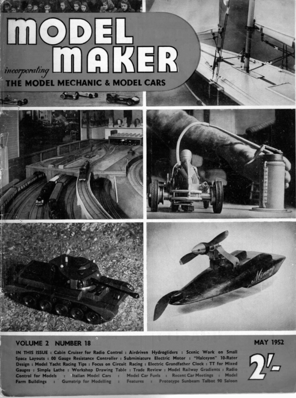
2 NUMBER 18 N THIS ISSUE : Cabin Cruiser for Radio Control : Airdriven Hydrogliders : Scenic Work on Small ce Layouts : 00 Gauge Resistance Controller : Subminiature Electric Motor : “Halceyon” 10-Rater : Model Yacht Racing Tips : Focus on Circuit Racing : Electric Grandfather Clock : TT for Mixed : Simple Lathe : Workshop Drawing Table : Trade Review : Model Railway Gradients : Radio rol for Models : Italian Model Cars : Model Car Fuels : Recent CarMeetings : Model n Buildings : Gumstrip for Modelling : Features =: Prototype Sumbeam Talbot 90 Saloon
May 1952 Halceyou ee lO – RATER IN PART DEALS 1 IN | JOHN DETAIL CONSTRUCTION: HE We AND ON EAL LEWES NEXT CONV -ER FINISHING COL O.U 8 A. WITH HULL MONTH PAINTING WITH NO TES S-C-H.E-M-E>S… HE “bread and butter’? method of building the hull of a yacht is about the easiest for the amateur builder, and as there are several advantages over the planked-up method we will choose this way of building Halceyon. Diagrams 1 and 2 show that the hull is laminated up in layers of wood which are, in this case, 1 in. thick. Some builders prefer to have the lamination running vertically, and this offers some economy in wood. The method to be described combines this advantage and the fact that it is easier to appreciate the final shape of the hull when built with hori- | ox suitable for a varnished boat, as there are often dark streaks in the grain. It is well worthwhile to have the timber machine-planed down to 1 in. thickness, which means that the planks will have to be about 14 in. thick in the rough state. You will require also, two pieces of obechi planed smooth to + in. thick, 6 in. wide, by 6 ft. long for making the deck. Marking out the timber is the next job, and should be carefully done. Mark the layers directly | on to the timber by plotting the required dimensions direct off the full-size body plan. The use of paper templates is tempting, but can lead to considerable errors. As we are building the hull in two halves, it is only necessary to mark out the layers for one half as these can be used as templates for the other half when they are sawn out. Draw a datum line on the timber and mark off section lines at right angles at a distance of 2.6 in. apart. Measure off the distances from the centre line on the body plan to the edge of the particular waterline at each section, and transfer all the dimen- “ i ‘ ! 1 TOP OF WORK BENCH I J KN T ! t f : VERTICAL LAYER FIG. 2. END VIEW OF CLUED UP HULL RUNNING FORE & AFT LAYERS. zontal layers. The principle being that the hull is built up in two halves with one vertical layer running through the centre fore and aft. This vertical layer is cut to the profile of the design, and if a centre line is scribed down its length, we have a permanent datum line on to which the keel and skeg can be lined up. The section spacing can be marked off and will not be lost until the final sandpapering of the carved hull is started. Obviously, the first job is to find some suitable timber. ‘The best wood to use is either yellow pine or white pine. Unfortunately these are almost impossible to obtain today. There is an imported hard wood, free of licence, called obechi, which makes a good substitute and i is in plentiful supply. It is light in weight and easy to work, but is not 3/6” DIA. HOLES FOR EEL BOLTS f Py “4 cr 4 3 ; if c — [ + a Z LM + # iF Wi | oe ne JOINT HERE LEFT UNGLUED TO FORM DETACHABLE KEEL. 4 saa aes —— S| , LW, : —Lue, [ FIG. I. SIDE VIEW OF a GLUED 345 UP HULL BEFORE CARVING. BENCH 7 Top ~ 77?
MODEL MAKER sions to the section lines on the timber. Join up all the points obtained with a fair curve, and we have the outer edges of one layer. As each layer down to the one below W.L. No. 6 is to have the inside cut away, we must plot this inside line next and ensure that sufficient timber is left to provide adequate thickness for the finished hull. It is obvious that section widths for the inside line will follow that of the W.L. immediately below, less the allowance for hull thickness. The easy way of obtaining the correct width is to mark on the W.L. of the body plan a spot where the inside surface of the hull would cross it. The width from the centre line to this spot being the required dimension. This need only be done for every third or fourth section. The marked-out layer should look something like Fig. 5. The thickness of the finished hull should be about 1/5th in. increasing to % in. at the centre line, except at the stem and stern, where 2 in. and 14 in. respectively is required to obtain the necessary strength, In order to preserve the shape of the layers during glueing-up a minimum width of 1 in. should be used. This will apply particularly to the layers above the load water line. Notice also that where there is tumble home of the topsides, extra width must be allowed on the upper layers to enable this to be carved (see Fig. 3). FOR VERTICAL LAYER 5 fic. WHICH AFT RUNS THROUGH {—paTUM LINE CUT BACK 1/2”— MARKED OUT HALF LAYER marked profile, and a centre line scribed down its length. Glueing Up There are several suitable glues obtainable, and these are of two basic types: (a) the casein glues; (b) the resin based glues. It is recommended that resin glues are used as they are more durable in damp conditions. Of the resin glues the gap-filling cold-setting type is most desirable, and there are several manufacturers. These glues usually consist of the glue and a hardening agent which, when added to the glue, starts a chemical action, hardening off the glue in normal room temperatures. The glue may be applied to one surface of the joint and the hardener to the other surface; on cramping up, the hardener will meet the glue and Alterthe necessary chemical action will start. natively the hardener may be added to the glue before application. Where a good glue line can be achieved it is better to use the separate application method, thus saving wastage due to mixing an ex- cessive quantity, and there LAYER FORE OUTER EDGE OF LAYER ay Ete omer 3/16” SCREWED ROD NOTE VERTICAL INNER EDGE OF LAYER CUT BACK 1/2” TO ALLOW = cd & HULL —4 CRAMP FOR GLUEING UP WING NUT WASHER TIMBER BATTENS 3 REQUIRED. is more time to get cor- rect alignment of the joints. Most of these glues have e only a short storage time, usually two to three months. There is a type consisting of a dry powder which has to be mixed with water before meeting the hardener, and this type, in its dry state, has a much extended shelf life. FIG.3. Fig. 6 shows a simple type of cramp which can be used during the glueing-up process. When each half of the hull has been built up down to W.L. No. 7, it is necessary to glue the two halves to the central vertical layer. This will be simplified if small wooden TYPICAL CROSS SECTION OF HULL. WIDTH FOR INSIDE OF LAYER the The above procedure is carried out for all 7 No. W.L. from that note but layers in the hull, halves, the the layers are complete and not in twofar. vertical layer only extending down this layer “Allowance has to be made for the verticalparall el layer half each off cut tely and 4 in. is accura to the datum line. The vertical layer is marked out in a similar manner to the others. It will be seen that considerable economy in wood can be achieved by nesting the half layers one inside the other, and is made more effective by buying the timber in blocks are glued to the halves so that G-cramps can be applied across the central layer. These blocks Feet be carved off when shaping the outside of the ull. The layer between the W.L.s 7 and 8 is now glued to the main hull. The remaining layers can be glued up after the hull has been carved. The actual carving is quite easy and only requires a certain amount of patience. The few essential tools are a block plane about 8 in. long, a 1 in. paring chisel, a 4 in. outside ground gouge, and lots of glasspaper. The initial rough work on the outside of the hull can be done rapidly with the 1 in. chisel. The block plane is used for most of the shaping, and when the strips on the hull have almost gone templates made of stiff cardboard should be applied to the hull to check the shape. With the plane set very fine it is possible to obtain a remarkably fair hull, but the widths of about 9 in. The layers are sawn out § in. clear of the marked lines and the section lines are continued round each face of the layers. The outer edge of the vertical layer can be planed down to within ;4 in. of the 346
May 1952 final shaping must be done with glasspaper. I find it convenient to wrap the paper round a cork pad about 3 in. wide x 6 in. long x } in. thick. It is advisable to shape the hull at a constant rate all UPPER DECK OF PLASTIC ——_LW.L. 5/16” BORE RUDDER TUBE CUT BACK ON EDGE OF SKEG TO ALLOW ROTATION OF RUDDER ing the final shape, view the hull from a distance never cast a keel then I would advise you to have it done at a foundry or by someone who has some experience. With the present high cost of lead the actual casting charge is very small, and I have never bothered to cast my own keels since my first horrific The point to insist on is that the holes for the keel bolts are cored, as drilling 347 POST THROUGH ABOUT SKEG – aire oa ee ee ne Fa} \ ears \_ – 90° RUDDER POST, 1/4“DIA. TUBE PLUGGED AT EACH END ae mr leis TO Hoa ee | pttiew Bagife FORM BEARING. & DRILLED PART OF NFFDLE RUDDER FIG. 2 te LOWER BEARING — RUDDER TUBE eee : 1/4”SQ BRASS FIG. 8. a ee a TUBE eee OR BAR MAST STEP these holes afterwards is an extraordinarily laborious process. While the keel is being cast the deck beams should be made and glued into the hull. The amount of camber to be allowed is +4; in. amidships and reduced proportionately as the beams become shorter towards the ends of the hull. Beams should be arranged to come in the following positions: fore and aft of the hatch, fore and aft of the mast slot; just forward of the rudder tube, and intermediate positions near the bows and aft of the hatch. At this stage the rudder tube and skeg should be fitted. The skeg is simply butt-jointed and glued to the hull, and the brass rudder tube will provide quite adequate strength. The rudder post itself should not be less than 4 in. 0.d. brass tube, and the tube must be large enough to allow perfectly free movement of the rudder post, say, %; in. id. minimum. The deck is a straightforward job, but do not for- get to glue blocks of hardwood to the underside in way of the main deck fittings. The mast slot should be about 3 in. long by 8 in. wide, reinforced down the sides, and the hatch can be about 3 in. wide by 43 in. long. The deck and the inside of the huil should be given at least three coats of good yacht varnish, the first coat being 50 per cent turpentine. The mast step is now fitted and the deck screwed or pinned into place whilst the last coat of varnish is still wet. By now the keel casting should have arrived and can be cleaned up as necessary. In Halceyon it will be seen that if the keel is made detachable, as re- commended, it is necessary to secure part of the deadwood to the after face of the lead. This is done by screwing a # in. square strip of hardwood to the lead, brass screws, of course, cutting a # in. groove in the deadwood and. then glueing the wood into position. This has proved satisfactory in the prototype, but perhaps there are better ways of doing the job. Incidentally, lead may be planed quite easily if the plane is lubricated with turpentine. The hull can now be sanded down with a very fine grade paper and made ready for painting. — narrow tool rather than a wide-bladed one, as the former is much easier to control and requires less effort to cut the wood. Note that extra thickness is allowed at the gunwale to enable the deck beams to be matched in (see Fig. 3). Finishing off the inside of the hull may be done with a small round soled “fiddle” plane, but failing this tool, glasspaper can be used. The weight of the hull at this stage should be about 34 Ib. The hull and the remaining unglued layers may now be drilled for the keel bolts. The position for the holes will be 24 in. fore and aft of the C.B. marked on the plans. The keel can be made detachable from W.L. 10, in which case the holes above this W.L. should be + in. dia., and the holes below should be + in. dia. Brass tubes 3/16th in. bore are fitted in the upper part of the keel, and project about | in. into the interior of the hull. Oak spacing pieces are slipped over the projecting tubes and glued into place. The keel bolts are made from 34 in. brass or stainless steel rod with a nut screwed on the lower end and a wing nut on the upper. The keel layers may now be glued together using the keel bolts as a cramp. The carrying handle can be made of 4 in. dia. aluminium tube flattened at each end and drilled to fit over the upper ends of the keel bolts. The keel is shaped in a similar manner to the hull and the lead line marked out. The pattern for the lead is cut off with a fine-bladed saw. If you have PROJECTS LW When near- Cutting the sheer is the next job, and this can be marked out by using one of the waterlines as a datum and measuring the required heights off the plans. The point to notice is that 4 in. must be subtracted from these heights to allow for the thickness of the deck. Hollowing out the interior of the hull must now be tackled. The first requirement is that the work should be securely held, and I find that one of the easiest ways of doing this is to drive two large screws through the bottom of the hull into the bench and fix packing pieces under each end of the hull for additional support. The principal tool used is the x in. gouge. It is usually more convenient to use a POST 1/2” ABOVE DECK. CELLULOSE at all angles in daylight and the unevenness of the surface will be more apparent than if viewed at close quarters under artificial light. attempt many years ago! RUDDER 3 FILLET over rather than finish off one side at a time or even try to get one template to fit at a time. BEARING BEAM
May 1952 WwW. Jes DANIELS WEALTH TO OF INITIATE INTO THE DIPS HIS WIDE THE ART NOVICE OF PREPARATION ENaTtO > THE EXPERIENCE RACE AND SKIPPER WINNING TALC TLCS Ready for Racing THE previous article will fortify the model yachtsman with the knowledge that he must not assume that everything is perfection to start with, and that only sailing experience is necessary for him to be successful. The model must first be brought up to a point where she will be easy to sail. In other words she must sail equally well with the same trim of sails on every course, unless there is a shift of wind. It is consistency of performance that brings success. It must not be a matter of guessing what the strength of the wind is going to be that will determine the trim of the sails. It is obvious that the strength of the wind is very seldom the same throughout the length of the course. When once you have determined the best trim for your model to such a windward course do not try to make her sail closer because you know that your opponent’s boat is very close winded. Lee & Weather Berths Should you be favoured with the weather berth your best chance is to hope that you will forge ahead proficiently to cut his wind, in which case MODEL YACHT RACING TIPS wind from your opponent’s sails and this may make just that difference that will enable you to cross your opponent’s bow when you reach the next tack. As you near the last tack before the finish the direction of the wind will determine if it will be profitable to make a short tack or go right across. It sometimes happens that the wind suddenly gets more abeam during a course to windward than it was at the start. The angle as per sketch will show how much shorter course will have to be sailed to reach the finishing line by making a short tack than by continuing to sail the full width of the pond. The manner in which a model is made to tack is by means of a gye. This is a length of line passing from the end of the main boom to a point forward on the gunwale. Its length can be adjusted by means of a hawser. The cord should not be the full length but should have a rubber cord extension to give a slight elasticity. In earlier years when sail plans showed greater disparity between jib and mainsail areas, this was found sufficient to make the model tack, but the larger jib to mainsail proportion now makes it necessary to lead the gye back through a pulley on the gunwale to the steering quadrant, so you may kill his speed and pass clear, and you will that the rudder assists in bringing the model round to the original tack. of your sails. Should, however, you have the lee berth you may, if your model is sufficiently fast to enable you to Beam Wind So much for sailing with the wind ahead. It is however, sometimes possible to sail the course with- have your opponent sailing in the distinct draught keep your wind clear, nullify the partial vacuum under the lee of his sails. effect to that of blanketing. in real yachting and is This will have a similar This is common tactics a_ perfectly legitimate manoeuvre. Tacking If the course has the wind so much down the course that the models have to tack, you will find that you will be faced with having to make quick decisions according to circumstances. If you have drawn ahead of your opponent at the time when up to your judgment to decide if you can cross the you can cross safely, If you decide put the model boldly about upon the other tack so that she does not lose way. run a risk of the other model touching you, in which Should you decide that it is not possible to cross safely you should put about as close under your opponent’s stern as is You will then get the greater impulse of possible. a the sails full. The pin rack can be used to check Sailing With Wind Dead Aft If the course to be sailed is with the wind dead aft or nearly to the sails must be paid off, always taking care that the wind is passing across the sail from luff to leash, and never blowing directly at right angles to it. Should the model get so much off the wind that the latter occurs, the model will slow down as a cushion of dead air will build up on the Unless you do this in a manner that will not fill the sails properly you will not only lose distance but case you will be disqualified. the wind is at least 45 deg. free. In this case you will use your closest trim of sail and fit your gye to ensure the model keeping on the same tack. Should the wind be dead abeam you will have to free off the sails and use the helm to keep the boat driving hard. The manner in which helm is applied will depend upon the type of steering that is fitted to the model. If quadrant steering is being used the running lines will be brought into play. It will be found that very little helm will be needed to keep the rudder from going too far, as after a certain point is reached the increased speed of the model will make the rudder increasingly effective in keeping the boat on her course. you have to go about on the other tack it will be other model without touching her. out tacking, but this generally cannot be done until 359
- MODEL MAKER sail and kill the driving force. Should the yacht set so far off the wind that the back becomes the leading edge, she will become what is known as “by the lee’, and a big drop in speed will follow. Ifa yacht with spinnaker set gets by the lee the mainsails blanket the spinnaker. There is an idea of setting the mainsail slightly too close in order that the draught from the latter spills into the spinnaker, but the writer has not noticed any advantage from so doing. The parachute spinnaker must be set outside or forward of the jibstay, but unless the wind is dead aft or nearly so, it will generally pay best to set a flat spinnaker inside the jib, letting the latter off sufficiently for the spinnaker and jib to form one sail. In racing it should be the aim of the skipper to keep to the lee shore rather than the weather one. It is, of course, best to sail down the middle, but you will invariably lose the race should you go to the weather shore unless your opponent is badly off the course. In most lakes there is a stronger wind to leeward, and it is much easier to re-trim your model. Opponent’s Tactics Unless your opponent is obviously wrong, it is generally profitable to pursue the same tactics. If the wind is inclined to set more abeat, it is better to have to make a short tack at the finish rather than risk getting up under the weather bank. Any obstruction to windward will cause wind eddies. An obstruction to leeward will cause an area of dead air that will steer the wind up and leave a calm spot. Care should be taken to see that the sheets run truly across the travellers as many a vital heat andg the race has been lost by this happening. Steerin pulleys should be oiled. Nothing should be left to on chance. Do not depend upon numbers marked the booms for trimming the sails. A slight change in temperature or humidity will allow the sail cloth to stretch or shrink and alter everything. Rather set your sails by judgment. This is not difficult if you concentrate on doing so. Constantly watch to see that the sails are hauled out on the spars just enough to take out any wrinkles. See that the main boom swings freely on the goose- neck as in light airs it will prevent the pull being taken on the mainsheet if it binds. Away Matches Should you have to carry your model to sail on a strange water, careful note should. be made to inner line of the battens is very detrimental to good performance. This is caused by an effort to get an excess of area in the outward bow of the leach. Experience shows that unless the cloth is stiffened by some doping process an outward bow of 2 in. per foot is as much as the batten allowance will support. Constant watching for changes of wind direction and the use of the correct suit of sails according to wind strength are very important to success. Always sail your boat rather under-canvased than over-powered. Use your own judgment and do not necessarily copy other competitors unless they are obviously right. No yacht is doing her best if she has water on deck, so canvas her so that her gunwale is never awash. Steering Gears Up to this moment mention has not been made on the use of steering gears. Until recent years the method of steering has invariably been by the pull of a steering line from the main boom to a quadrant fixed to the rudder stock. On principle this is an excellent method providing it is arranged correctly. Its success depends largely upon the nicety of balance of the pull on the running sheet, and the tension on the elastic centring line. Also the area of the rudder must not be excessive or it will be forced straight by the water, and have no steering effect at all. The general principal of setting the correct setting is to note how the model acts. If you find that she falls away off wind directly the wind gets light it means that the centring line is not tight enough to bring the rudder back amidships. If, however, she starts to go up too much directly the wind increases the centre line is too tight. The tension should be arranged so that whilst bringing the helm amidships with no strain on the running line the slightest pull on the latter immediately starts to operate the quadrant. The amount of helm can then be adjusted by the distance out on the steering quadrant from which the pull is taken. In 1935 the challenger from Norway for the International “‘A’’ Class Cup introduced a new form of steering. This was by means of a wind vane fitted at the stern of the model. This vane operated a lever which latter was attached to the tiller from the rudder head. It operated very well, but had one disadvantage in that it had to be readjusted for tacking which required that the model had to be stopped with resultant loss of time and distance. It was not long, however, before a method was found to make the vane setting reverse itself upon the model being put about with the result that the method of vane steering became very popular. There are, however, conditions in which the quadrant steering will give better results, and whilst with the wind steady the vane method is almost as good as a man at the helm, the average model yachting lake has so many obstructions that cause wind eddies that ensure you get your mast in the same position. This is best done by noting the distance from a given point on the mast to stern head. See that your mast is straight and the jibstay as tight as possible. A sagging luff prevents the jib making a true aerofoil, Should your mast bend the mainsail will lose its shape. There is such a little difference in the cut of a good mainsail and a bad one that a curved mast will alter it considerably. A pocket formed at the over-sensitive steering is not desirable. 360
May 1952 Model Yacht Club Notes ae? WE have now had an opportunity of perusing the 1952 MODEL YACHT M.Y.A. Club and Fixture List. There are sixty-two affiliated clubs in England and Wales and another thirteen in Scotland. A nice round total of seventy-five, which should make the task of producing a monthly page of CLUB club news a sinecure, but alas, very many clubs have not as yet taken advantage of this offer of space to send in paragraphs. We hope these laggards have all been too preoccupied with a bumper fixture list, and can now relax long enough to tell us about themselves. Editorial sackcloth and ashes must be donned and our house flag flown at half-mast for a misleading comment in our April issue. This old established club—which may justly claim to enjoy some of the finest boathouse and other sailing amenities in the land—is not, in spite of its title devoted to the “Wee Six” class, but derives its title from early association with the Yachting Monthly 6m Trophy Races, out of which developed the present A Class, evolved by Major Heckstall-Smith and assisted by our friend W. J. Daniels, who is still producing top class designs in this and many other racing classes. All the fixtures listed, Hon. Secretary Hatfield has has- tened to point out are for A Class Yachts, and not, we repeat, not for 6m boats. Scotland reigns supreme as ever in this particular category ! Model Yachting Association We have just received M.Y.A. News No. 30, dated February, 1952. It is in effect a review of last season’s principal events, and contains a lament for the quality of British designs. Just why American designers are beating our best boats is hard to see. There is no America’s Cup business of having to sail the challenger across the Atlantic. Even in our difficult financial state there are still plenty of people able and willing to find time and money to build new yachts, though there is some degree of affection for older boats that have served their skippers well since prewar days. Is it, as M.Y.A. News suggests, a matter of a dearth of new designers? If so, what can we do to pro- mote a re-birth of designing enthusiasm. Top class craft in the A Class do indeed cost quite a few pounds, and may take a lot of time designing, so that we feel some gesture of financial support might encourage the younger and more penurious school to try their luck. Model Maker is pre- pared to enter into negotiations to buy the design rights in this year’s A Class Nationals winner, to include a con- structional series of articles on its building, provided that the winning boat is a new design that has not been raced before 1951, and that it is the original design of skipper, mate or entrant. “COMMODORE” Ngee Mr. Marston’s Cup : YM 6m Owners’ Association their BY NOTES By original, we mean original to the de- Sept. 20th—Inter-Club. New officers elected are : C. Marston, Commodore; S. R. Pepper, President; K. C. Marston, Hon. Secretary; T. Crewe and L. Stevenson, Club Measurers. Amongst new boats sailing this season will be two. Marbleheads and a 10-rater. Newcastle M.Y.C. Well off the mark with the season’s sailing is Newcastle M.Y.C. with their M.Y.A., N.D.C. Marblehead Championship. Hon. Secretary Andrews provides a full report : “Blizzard Weekend”, 29th/30th March, saw the staging of this event at Newcastle-on-Tyne, the first time a race of first-class importance has been held there for Many years. Entries had been received from several Lancashire clubs; one stalwart, Mr. Smallwood, made the trip from Belfast, and there was a full entry from the local club. Mr. Andrews’ newly launched Nimrod, from the Jocal club, was allowed to enter when a last minute scratching would have provided a bye. Among well-known boats entered were K. N. Jones’s Gazelle and Mrs. J. Chipchases’s Alma, while R. Bradley’s new Black Hawk was universally admired, Conditions could hardly have been worse as the first pair came under starter’s orders at 11.15, with a N.E. wind driving the snow across the lake. This wind gave a very tricky reach, but all hands quickly settled to conditions and some very skilful sailing was séen until completion of heats for the day at 5.30 p.m. The snow had cleared when racing was resumed the following day, but the northeaster remained as vicious as ever. Again close sailing was the order of the day, and at the conclusion no less than four boats had tied for first place with 24 points. A four-boat final was then sailed to decide the finishing order, The score sheet was : 1. 557 2. 428 3. 427 4. 516 5. 551 6. 463 7. 528 8. 509 9. 163 10. 189 Black Hawk—R. Bradley, Bolton 24, Gazelle—K. Jones, Morecambe 24. Alma—J. Chipchase, Fleetwood 24. Wildcat—F. Smallwood, Ulster 24. Nimrod—G. Kirtley, Newcastle 20. Renown—R. Threlfell, Vale of Lune Leonora—P. Dawson, Newcastle 18. Veyh—R. Patterson, Newcastle 12. 19. Valerie—J. Shiel, Newcastle 9. Sapper—J. Woodhouse, Vale of Lune 6. For this event the local tried an innovation which may well prove of interest to other clubs. Instead of sending visitors to hotels for the night they invited them .to their homes, thus serving the dual purpose of cutting signer, not an altered version of some other designer’s, but may be the logical development of a series of boats by the man offering the design. This in effect, offers the designer an opportunity to earn himself a sum in the neighbourhood of Twenty-Five Guineas, while retaining the boat and enjoying any of its future successes. We hope readers will pass this offer down expenses whilst encouraging greater comradeship. round to any interested non-readers. Elettra Model Boat Club Leicester Model Yacht Club We Following inter-club and open fixtures are announced : new Ratcliffe Trophy (10-raters) : April 12th—Inter-Club. 10-Rater Trophy: May 3rd—Open. are club just for in time Radio to announce Controlled Boat the formation of a enthusiasts. Hon. Secretary is F. C. Hird, 90 Aberdale Gardens, Potters Bar, Middlesex, and their water is Brent Reservoir (Welsh Harp), operating from the point where the Handley Page 50/800 Marblehead Cup: June 7th—Open. Mr. Pepper’s Cup : June 21st—Inter-Club. Sports Club ground joins the water. 361


