- Halceyon 10-Rater, By John A. Lewis , Part III Painting and Finishing the Hull
- Model Yacht Club Notes, By “Commodore”
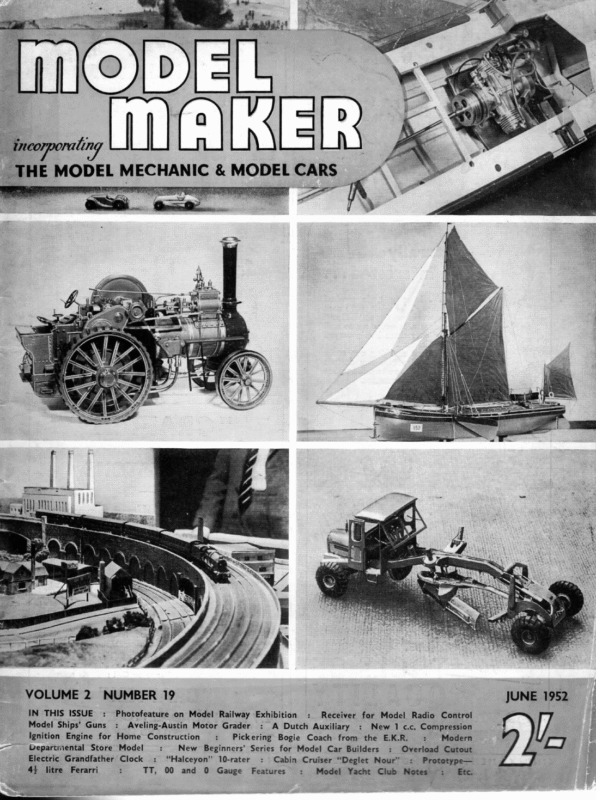
- A Dutch Auxiliary, By A.M. Colbridge, Though One of the More Attractive Prototypes, the Auxiliary Has Been Somewhat Neglected By Model Makers Who Will We Hope Discover a New Interest in This Fascinating Design.

MODEL ma Be JUNE 1952 NUMBER 19 IN THIS ISSUE : Model Ships’ Guns Photofeature on Model Railway Exhibition : Aveling-Austin Motor Grader Ignition Engine for Home Construction -— Departmental Store Model Electric Grandfather Clock 44 litre Ferarri : : : TT, New : Pickering : Receiver for Model A Dutch Auxiliary Bogie : “Halceyon” 10-rater Gauge O : Coach from the E.K.R. : Cabin Cruiser “Deglet Nour” Features Radio Control New 1 c.c. Compression Beginners’ Series for Model Car Builders 00 and : : : Modern Overload Cutout : Prototype— Model Yacht Club Notes -: ee VOLUME 2 . _ THE MODEL MECHANIC & MODEL CARS
MODEL MAKER JOHN LEWIS’S “ HALCEYON ” HAS NOW HAD TWO WINS IN TWO OUTINGS, BEATING SOME OF THE BEST IN THE MIDLANDS, WITH HIGH POINTS ON BOTH LEE AND WEATHER BERTHS. the middle two-thirds of the hull, then that is near enough at this stage. Using the above method as a check, the prototype finally measured, 51.92 in. for on rating purposes, the L.W.L. as against the designed 52 in. I believe this to be as accurate as is necessary, and as a point of interest no adjustment to the lead as designed, was required. Carry out the above test quick- ly and wipe off all surplus water when completed, as the hull is not yet fully waterproof. T has been mentioned that a good, smooth, finish is very desirable on a boat in order to reduce the sheer friction. A good finish is not difficult to obtain and only requires a little more than average patience. It is necessary, of course, to obtain the smoothest possible surface on the hull before starting to paint, and any blemishes or dents can be filled up with cellulose stoppers. This is a grey plastic which sets very hard quite quickly, but remember that as we shall be using an oil-bound paint, it is not advisable to use cellulose stoppers after any It is strongly recommended that the hull is painted in two colours, meeting on the L.W.L. This means more trouble, but it makes all the difference to the look of the final job. A ‘‘one colour’ boat always tends to look heavy and ungainly. The same applies to a varnished hull, which never seems to have the slick appearance of the painted boat. Colour schemes are a problem to some people, so here are a few suggestions which have been found to look very satisfactory : — ——— Pale blue and cream. Bottle green and Eau de nil. Black and cream. Black and jade. Maroon and cream. Grass green and cream. . Maroon and grey. My favourites are 2 and 5. In each case the darker colour is the topsides, and there are two reasons for this. Firstly, it is my opinion that it makes the boat look more sleek, and secondly, it ties up with obtaining an attractive deck. This will be explained more fully later in the article. NAAR YN Se paint has been applied. The hull is first treated with two coats of varnish thinned down with genuine turpentine; this soaks into the wood, making a good primer. Rub the hull down lightly with fine glasspaper and we are ready for building up the coats of paint.. However, before applying any paint it is well to test the hull for correct flotation, so that trimming of the lead, necessary to correct errors in the L.W.L. or fore and aft trim, can be made. Float the hull in a suitable bath or pond, and place on the deck weights equivalent to the masts, sails, fittings and vane, etc. For this initial check the following weights will prove near enough: 1# Ib. over the mast stip; + Ib. 4 in. aft of the rudder post (the rudder should be in position), and 14 Ib. midships, this latter weight being the allowance for deck fittings and paint. It will be necessary to record the position of the waterline, so that the junction of the two colours will be in the correct place. This is easily done by measuring the distance from the gunwale, round the surface of the hull to the L.W.L. at intervals of about 3 in., and keeping a note of the dimensions. Make sure that the hull has not taken up a list, and as one of the joints coincides with the L.W.L. it will be obvious if the trim needs adjusting. Do not be misled by the meniscus of the water up the sides of the hull, as this gives the impression that she is floating too low. This is particularly noticeable under the overhangs where the hull leaves the water at a fine angle. If the trim looks right over The hull should now be given a coat of good quality lead paint, this being rubbed down smooth with glass paper. Several coats of flat undercoat paint are now applied, and after each coat the hull is well rubbed down using fine “‘wet or dry’’ paper. This is a carborundum abrasive paper and is used wet. One of the secrets of a good finish is keeping the 412
June Halceyou IO-RATER PART fib. PAINTING FINISHING work really wet with water during rubbing down, and as soon as any hard particles are felt to be grinding into the surface, the paper should be well washed out or thrown away. Do not be satisfied until a really good surface is obtained, and providing the rubbing down is done thoroughly and the paint applied in thin coats, anything up to eight coats can be put on. It is important that the paint is allowed to be quite dry before rubbing down; it is fortunate that undercoating usually dries quite quickly, and 48 hours is an adequate time to allow, providing the paint is applied thinly. When a satisfactory finish has been obtained the waterline can be marked out and the first coat of finishing enamel applied. It is usually more convenient to paint the bottom of the hull first, particularly so if it is the lighter colour as previously suggested. In order to ensure a firm line between the two colours, marking tape must be used. I find that Sellotape $ in. wide is quite suitable, but care must be taken that the paint to which it is stuck is thoroughly dry and hard, or it has the tendency to pull the paint off when removed. The marking tape should be removed immediately after the paint has been put on, thus preventing a ridge from building up at the junction of the colours. When dry, the first coat of enamel may be rubbed down with the finest grade of ‘‘wet or dry’ paper, or with a wet cloth pad, and powdered pumice. If all goes well, the last coat should give a finish completely free of brush marks and with a high gloss. To obtain the very best results it is, of course, necessary to use only the finest quality materials. A good brush is difficult to obtain, and once one has one that is satisfactory, it is well worth looking after. I find that a $ in. brush is about the right size for the job, and I use one particular one for all finishing work, cleaning it out after each time it is used, and again before resuming it, to ensure that it is free from bits of old paint or dirt and dust. Providing the enamel is of a first class make, and that the undercoating recommended by the manufacturers is used, a good job should be the result. Unless a special Marine enamel is purchased, it is well to make sure that the enamel is suitable for exterior or for interior use. The undercoating need only be of the colour suitable for the lighter finishing coat, and can therefo re be used over the whole hull surface, so effectin g some economy. ‘Two coats of finishing enamel are 413 THE 1952
MODEL MAKER ¥ quite adequate to cover up the lighter undercoat. Enamel requires to be brushed on with considerable care, as it must be of sufficient thickness for the brush marks to fill out and yet not to form runs on the surface. It is probably easiest to brush in the opposite direction from that which you are painting. This means that the enamel is laid on to the surface and then brushed back on to the work that has already been covered. With practice, a surface completely free of brush marks can be obtained by this method. Temperature has quite an important bearing on the quality of finish obtainable, and in order to achieve the best results, the room in which the work is done should be at about 70 deg Fahr. It is a waste of time trying to do good work in a cold workshop on a winter’s evening, and I find it necessary to annex a spare bedroom for this work, making sure that no one enters until the paint is dry. Remember that the hull, the paint and the room, should all be at about the same temperature. The deck is finished in the same manner as the hull as far as obtaining a smooth surface with undercoating, and can be done together with the hull if arrangements are made to hang the boat up, thus saving a lot of time. Give the decks two coats of cream enamel and rub down the last coat with a very fine “‘wet or dry”’ paper to a perfectly smooth and matt surface. It is now necessary to line the deck to represent planking, there being two systems and methods of doing this. IO RATER SHEET “HALCYON’ 2 _ SAILPLAN. 76-0 TO DECK. The first system is with the lines running straight fore and aft, parallel to the centre line; the second being with the lines running parallel with the gunwale and meeting on a kingplank down the centre line. The second system is much preferable and is in fact of the best yacht building practice. The lines are put on with the draughtsman’s ruling pen and black Indian ink. Some recommend that a holder for the pen rather like a marking gauge is used, the gauge being run along the deck edge for a guide. Personally I prefer to make a template of 4 in. obechi, and use the pen in the normal way round its edge. The procedure is first to rule two parallel lines 4 in. apart down the centre of the deck to form the king plank, and then with the aid of the template start ruling in the planking, working from the gunwale towards the king plank. The lines are spaced about + in. apart, and with a little practice it will not be necessary to measure the spacing each time. When one half of the deck is lined out put a pencil spot on the edge of the king plank corresponding to the termination of each line; this is to ensure that the planks on each side of the deck come opposite to each other. Take care not to smudge the lines for it is not possible to rectify a mistake without cleaning off the whole deck and starting fresh with another coat of cream enamel. As soon as the ink is dry, the deck should be given a very thin coat of varnish. Thin the varnish with about 10 per cent turpentine and add just a spot of terebine driers. This will fix the lining, dry rapidly and leave a good gloss surface. The colour will change slightly from cream to a stone colour which is quite attractive and acceptable. The deck edge and the king plank should be painted the same colour as the topside. If the topsides are of a darker shade, the general effect is very pleasing. It is risky to use marking tape on the deck as too much work is spoilt if the varnish lifts off as it is removed. I had it happen once, and since then always go round gunwale and king plank freehand. It usually takes about two hours, by which time I am trembling like a leaf and have become quite boss-eyed! The brush used for this purpose is a chisel shaped, 4 in. wide, best quality camel hair. If care has been taken the boat should have a finish as good as a new pre-war car body. A small point which I think is worth mentioning here is that the turning pole, used when sailing the boat, should have a soft sponge rubber sleeve as a lot of damage can be done to the finish if the pole is not well protected. During the painting process a lot of time is spent waiting for the paint to dry, and if the work can be done in a spare room it is possible to get on with making the masts and spars and some of the fittings. READERS ARE REFERRED TO OUR PLANS SERVICE ADVERTISEMENT (FRONT OF THIS ISSUE) GIVING DETAILS OF DRAWINGS FOR THE 10-RATER “HALCEYON”. 414
June 1952 WE are happy to report that more clubs are sending in details of their activities, together with results of club events. MODEL YACHT It would give an added interest to such reports if Press Secretaries would make a point of including registration numbers as well as names in the results. Still more club news will continue to be welcome. We also await volunteers from Scottish clubs to report their two National events. CLUB Birmingham Model Yacht Club BY. NOTES ““COMMO DO RE? The fifteenth annual Thornton Trophy took place at Watton-Lakes on April 19th, when twelve 10-raters came under starter’s orders. Racing commenced in brilliant sun- shine with yachts carrying full canvas and making excellent heats. A freak storm suddenly descended and gave skippers the harassing work of reducing sail in windward boards, and the use of pocket-sized spinnakers for the runs were in evidence. Competition proved keen, with some close finishes by the leading craft. Heavy weather forced the retirement of two yachts owing to gear being broken and carried away. Dr, P. Thornton, donor of the trophy attended the meeting, together with Midland District Committee officials, and Miss Linnet Pitt, who presented trophy and prizes. Results were as follows : 1. 2. 3. 4. 5. Halceyon—J. Lewis Opal—J. Drury Cunior—F. Pitt Jill—E. Locks Flook—J. Meir pts. 39 39 29 26 26 6. 7. 8. Dolly Grey II —D. Lippett Beatrice—H. Bach Samphire —M. Brueton pts. 24 17 10 9. Dolphin—G. Brown 7 10. Valkyrie—E. Mills 3 Lady Gay (J. Penn) and Seagull (J. Bradnock) retired. We are glad to report this success by John Lewis, who is to be congratulated for his fine sailing, and excellent design—the latter can at any rate be shared by readers, oe 10-rater. Halceyon is now being published in Model Maker. Fleetwood M.Y. & P.B.C. Fleetwood A. Class yachts opened the club’s 1952 season on Good Friday with the Hayes Trophy, sailing in eleven heats. Light south to south-west winds prevailed through- out the day causing some trouble to competitors due to the promenade buildings obstructing the wind at the west end. Racing was, nevertheless, close and exciting, with inches between the yachts on several occasions which added to the enjoyment of the large holiday crowd. A further round was sailed before lunch on the Saturday, but a dearth of wind by 4 p.m. made it necessary to declare a result on the first round only. This gave a closer finish to a Cup Race than the club has known for a long time, only eight points separating the first six places. Leading scores were :— 1. 2. 3. 4. Scamp—L. K. Corooin Westwind—R. Pilling Flame—£, L. Dawson Windward—Miss J. Rawlinson pts. are all out to do even better this year. Hove & Brighton M.Y.C. The club is now going forward with a full fixture list after a somewhat unfortunate start to the season when their first two events had to be cancelled owing to repairs to the Lagoon. We hope these wil] make sailing at this popular Sussex venue even more pleasant than in the past. Poole Model Yacht Club The new boathouse has now been officially opened by Mrs. Simpson, wife of the Commodore. All that is now needed to complete amenities is the catwalk enclosure. The opening ceremony was followed by a 36 in. restricted class event: Ist Teal (an omen which we trust members were quick to follow in the Grand National!), Mr. Keach; 2nd Blue Comet, P. Rogers; 3rd Whisper, B. Sanson. Marbleheads raced on 20th April: Ist Marconi, J. Horton: 2nd Pila, J. Jones, and 3rd Gobroon, D. Spicer. Our old friend Lt.-Col. Bowden has also recently given a demonstration of radio controlled boats on the club water, accompanied by Mr. Leigh. In view of the Colonel’s advanced ideas on sail design we have always been sorry that class racing has not attracted his interest, though perhaps this is because he is lucky enough to have a full-sized tiller in his hand on most summer sailing occasions. Paignton M.Y.C. The club’s summer season opened on April 6th with the Royal Torbay Yacht Club’s Silver Rose Bowl event for 10-raters. Fourteen yachts faced the starter from the home club supported by entries from Bristol and Exeter. A third suit breeze was blowing for the first heats, but within half an hour top suits were the wear, until the end of the event when wind completely failed. Commodore Pinsent was in great form, not dropping a point until the last heat or two. Results :— 1. Trixie—D. Pinsent, Paignton 45 2. Semper Fidelis—H. Isaacs, Exeter 41 3. Rose of Devon—R. Eland, Exeter 35, Semper Fidelis has only just been launched, built from a Littlejohn’s design, and this must be almost its first ap- 38 36 35 34 pearance amongst the winners. Rose of Devon is also a comparative newcomer, being launched last year from the Birkenhead M.Y. & P.B.C. We were glad to hear from Commodore A. R. Andrews with a fixture list and some statistics on last season’s successes by the club. Most notable honour was, of course, their Mr. W. H. Jones’ selection to represent the M.Y.A. unpublished lines of a design by the late W. H. Davey of Bournville, to whom John Lewis of Halceyon owes much of his designing skill.. Trixie, of course, is a well-tried favourite, and though—as can be seen—far from outclassed in this new company may be retired at the end of this season in favour of a more modern boat if the skipper’s eye falls on a design worthy to be her successor. Amongst visitors at the Rose Bowl event the club were particularly happy to welcome Mr. Windcart, Rear Commodore of the R.T.Y.C., well-known as a great West Solent helmsman. at Boston, in company with Mr. R. Jurd, of Gosport—a north/south combination which, though it failed to prove victorious, did much to promote Anglo-American sporting friendship. places in A Class, 10-rater and Marblehead, and Ist in Daily Despatch Cup Open Event at Fleetwood, plus a number of other worthy successes. This seems a good list for one club—certainly more than their share—and Commodore Andrew assures us members In National Events members collected 3rd in A Class, 2nd in 10-rater, and ist and 2nd in 36 in. Res- tricted Class, which was sailed on their home water, In Northern District Committee events they took Ist and 2nd 415
June THOUGH ONE OF THE MORE ATTRACTIVE PROTOBEEN SOMEWHAT HAS TYPES THE AUXILIARY NEGLECTED BY MODEL MAKERS WHO WILL WE THIS IN_ INTEREST NEW A DISCOVER HOPE OF SCALE A TO DESIGN FASCINATING FOOT THE TO INCH ONE APPROXIMATELY COLBRIDGE M. A. BY DETAIL IN DESCRIBED A DUTCH AUXILIARY puis is a very pretty little model designed on the lines of a typical full-size Dutch auxiliary, representative of a scale of roughly 1 in. to the foot. It can be powered by a small electric or $ c.c. diesel motor, or even a clockwork motor, and also by sail. The latter calls for the addition of a keelboard which, or carving from solid. However, the work has been kept quite straightforward, assisted by the fact that this type of hull has the minimum of compound curves. It goes without saying, of course, that the skinning must be applied accurately in order to produce a watertight hull, which was one reason why thin ply was chosen. Plywood of 1 mm. thickness possesses considerable strength, but at the same time is readily cut and trimmed with a sharp knife. in the case of the model, is made as a separate, detachable unit, bolted in place when required. There is plenty of scope in the design for the in- clusion of detailed fittings, and for experimenting with different forms of power units. No power unit installation is shown on the plans as details will vary with the type of power unit used. However, the open cockpit offers a space roughly 6 in. x 4 in., The plan shows the main outlines and details of the vessel, whilst the smaller sketches illustrate the various stages in construction. Assembly is around a keel member, } in. thick, and seven individual ply bulkheads or frames, plus the transom, all cut from vs in. thick material. Resin-bonded “waterproof” ply should be used here. Outline shapes of the bulkheads are given by the body sections on the plan. Each bulkhead can be fretted out to lighten, which is ample room for installing any type of power unit, once the hull has been completed. The stern tube is about the only tricky part and for preference this should be mounted in the keel member during the initial stages of assembly, if a powered model is contemplated. whilst bulkheads 6 and 7 are cut as indicated in the typical hull section drawing. Notches are cut in all the bulkheads and the tran- Construction is on somewhat unorthodox lines, using thin ply skinning instead of regular planking, ‘ 1952 som corresponding to the keel, keel stringers, chine ASSEMBLE FRAMES FRAMES SEATS. ETC., FITTED OD SIDE SKIN OF PLY MAST FITTIN 1S METAL TU KEEL NOTCH SHEER STRINGER ” Sees SS ae KEEL STRINGER A Z NOTCH a~ a CHINE STRINGER KEEL NOTCH —— SHAPED ee = BALSA PLANKING PINNED AND GLUED 419 DECK FITTINGS AFTER PAI IPLETED ING
HULL LINES > RAIL 3 PROFILE. 4 33 2g DY SECTIONS. : 7 : | ‘ SHEER: ‘ ‘ WATER LINE. KEEL4 2 4 TRANSQ\ | ‘ CHINES | 4 sf CABIN, FORMER 6 =maa> 4 RAIL FALSE SHEER. HULL ! SECTION = ae a 2= BULKHEAD 3. STRINGER. | if RAIL: Ot N LINE. HATCH, tha SEAR COCKPIT. CABIN. } bia COAMING. _|2-= | SIDE : SKINNING: — BOTTOM SKINNING CABIN SIDES 16 THICK nad fi a aul COAMING “16 THICK, rank: Z ipa HIGH——_J BOWSPRIT” STRINGER % x Foxe RAIL SHOWN. —S1¢) Bi! — | LA Sy =| 1S __ZNUT = ” Wo- shee. $ S ———-= = | MAST 4. | CABIN TOP 6 THICK. RAIL ta BALSA \o\—fp==er__E BLocK. 4 = FRAME |. SEK FRAME 2-5 F a — ee So 1 R I | |a Se : J FRAMES—-F] 3 +FRAME Tsu — += SS 5 SFllncer F F| ae KEEL assay 2, eel ~ = —— pr FRAME 4. | % – —— & — i —— = Sis =i apa BE ee, Tet kee |oe eee —_— SS SS = | | one ; 6PLY. : =| TRAN BE] | FRAME 6-& Sree oe HULL SECTION AT BULKHEAD 7, i hey /| : CABIN FORMERS. WORKING DRAWINGS WITH SCRAP VIEW THIS DRAWING IS EXACTLY ONE-THIRD FULL SIZE AND MAY BE SCALED UP. FULL NSIZE WATFORD, HERTS. PRICE 3/6 POST FREE ROAD, CLARENDO PROGRESS SKETCHES ARE AVAILABLE FROM MODEL MAKER PLANS SERVICE, 38 f
June stringers and sheer stringers. Keel notches are { in. wide and match with the notches also cut in the keel member. Keel stringers are x% in. square. Chine and sheer stringers are } in. x 7% in., subsequently chamfered off to conform to the lines of the hull sections and lie flush with the outer surface of each bulkhead. All notches must be cut as accurately as possible. The keel member is cut from + in. hardwood, and is half jointed to the raked stem, also cut from + in. Glue and screw this assembly. All the stock. bulkheads or frames and the transom are then assembled accurately on the keel, checking that they are square and correctly lined up. The two sheer stringers should then be cemented in place when the assembly can again be checked for trueness. Chine stringers and keel stringers are added to complete the first stage of the assembly. When set, chamfer off the chine and sheer stringers to conform to the shape of the individual frames. The extreme bow should now be filled in with balsa block forward of bulkhead 1. Templates of this shape should be used to ensure an accurate carving job as the planking rests on top of it. The two rail strips can now be fitted, cut from 1 mm. plywood. These can be cut to shape by trial and error, or a wide strip used, trimmed to shape after assembly. Pin and glue to each frame, and to the stem and transom. The main side skinning, also of 1 mm. ply, is then secured in a similar fashion, after which the hull can be turned upside down and the bottom skinning added. Probably the easiest way to do this is to trim the top of the side planking to the shape of the sheer line and secure in place. Then trim off flush with the bottom of the chine stringer. The bottom planking, just a rectangle of ply, is then secured in place and trimmed down when set. All the joints must be sound. The rail then needs backing up flush with the deck line between formers. This could have been done initially by notching rail stringers into the frames at the first stage of assembly, but the compound curve involved would make this rather a tricky operation. It will be just as effective, and much easier, if false stringers are added after assembly, trimmed to fit against the top of the rail when glued between the individual frames. The main point of these false stringers is to provide a good glue-down surface for the deck where it meets the top of the rail. The false stringers are trimmed down flush with the top of the rail. A rubbing strake should be attached to the outside of the hull over the joint line between the rail and side planking panels. Thin stripwood can be used for this, but would require notching to fit. A very good solution is to use leather strip, tacked in place at intervals of 1 in. or so. Plastic strip (braiding) is another alternative, but if this is used it should not*be secured until after the final paint job has been applied. The deck is cut from }, in. hardwood — good straight-grained stock which will bend to the required curve. The deck itself is flat laterally and so no difficulty should be experienced in making the bend. Check the deck for fit, making sure that all the frames are flush with the rail line and the whole deck seats down properly. Before fastening in position, however, attend to the necessary interior hull details. It will be necessary to fit a socket for the mast which is simply a short length of + in. internal diameter metal tube, slotted for about half its length to fit over the keel. This fitting engages in a notch in the keel and is screwed or bolted in place. If any interior cabin detail is required, this should also be added at this stage between Frames 3 and 5. In this case the cabin platform is cut out of the deck itself. Otherwise, if the cabin is to be purely ““dummy” the deck can extend uninterrupted back to the cockpit. Before fitting the deck, too, give the whole of the interior of the hull several coats of shellac or similar varnish to waterproof. Check all the joints for watertightness. The deck is attached by glueing and pinning to the frames, and glueing to the rail and rail stringers. Start by pinning down on Frame 4 and working fore and aft from this point. The deck should slightly overlap the rail all round, and can be made oversize in the first place, trimmed down to the required shape afterwards. In other words the deck can be applied as a rectangular sheet of -/; in. mater- ial with just the cockpit fretted out. The three cabin formers are glued directly to the deck in their correct positions, when the cabin sides and cabin top can be added. The windows should be covered on the inside with panels of thin celluloid before fitting the cabin roof. Cockpit details are completed by the addition of the seats, etc., and a t DETACHABLE Ye ENG ~e *FRansou RUDDER IS MADE DETACHABLE 1952
—— MODEL MAKER _ suitable flooring of 4, in. hardwood, secured between the frames. The for’ard hatch is cut from vs in. material and glued to the deck. The mast is a 20 in. length of + in. dia. dowel, tapered towards the top to roughly 4 in. diameter. A suitable hardwood cap can be fitted, if desired. The mast is made detachable for transport. The rudder hinge fittings, made from brass tube and thin sheet brass, should be screwed to the transom when the exterior of the hull can be painted and finished. In vessels of this kind it is common to see the rail left as varnished wood, finishing the paint line at the sheer line. The underbody below the waterline may be painted in a contrasting colour. Deck, cabin and coaming strips can be white. The latter are cut from + in. thick hardwood and simply glued in place. When the paint job is completed, other deck fittings such as cleats, etc., can be added, also the fittings for the mast shrouds and the bowsprit. The bowsprit is made from dowel, tapered off to the front and held down to the deck by two straps of brass or copper strip. A stay is carried back to the stem. The other rigging details are summarised in one of the detail sketches. The rudder is cut from +% in. material painted or just varnished. It is also detachable with simple pin hinges. Provision should be made for lashing the tiller at any desired rudder setting. No specific details are included of a suitable sail plan, but recommended dimensions are given in one of the sketches. Details follow normal model yacht- ELECTRIC GRANDFATHER CLOC K ing practice. For sailing, however, it will be absolutely essential to fit a keelboard for stability. The keelboard can be cut from 4 in. ply with two metal top fittings which engage the keel on either side. Point of attachment of the keelboard should be exactly underneath the cabin and suitable ballast is bolted to each side of the bottom of the keelboard to balance the hull, with sails rigged, parallel to the design waterline. When an auxiliary power unit is employed, attention must again be given to balance. If the power unit is fitted in the open cockpit then almost certainly ballast will be required for’ard to trim the hull properly. A good idea in such a case is to make the front hatch a proper hatch, using the space between Frames | and 2 as a compartment for storing the ballast, which can then readily be adjusted, as required. These and similar modifications to the basic design should appear fairly obvious when the model is completed and is being adapted for some particular. use. ! This model Dutch auxiliary is not a heavy weather model, so do not expect it to happily battle against “‘storm’’ conditions. Any water shipped will collect in the open cockpit and eventually the craft would become waterlogged. Nor can you expect to use it as a racing craft. It is a model for pleasurable sailing, so choose your weather accordingly. Use the sails in light breezes only, and if you must sail on a choppy pond, stow the sails and rely on the auxiliary motor. In other words, treat it as any self-respecting owner would a full-size auxiliary. (Continued from page 423) on a spindle which is driven exactly twice as fast as the ratchet wheel; the main minute hand will be geared down in the ratio 60 minutes: 30 seconds, i.e., 120: 1, and similarly for the hour hand (ratio 12 x 120: 1). Gravity arm and ratchet wheel must be very carefully mounted and the crutch pin located so that it is given its full sideways movement by the pressure of the pendulum bearing against it on each swing. It is a good idea to fit two stops projecting from the backplate to limit the actual pendulum swing to the maximum required, thus preventing any strain being produced by accidental displacement of the pendulum beyond its normal amplitude. train assembly, complete with hands, can be considered as a separate item which is merely offered up and secured in the top part of the case and driven by the ratchet wheel spindle. The ratchet wheel itself is driven by the gravity arm, displaced when the crutch pin mounted on it contacts the pendulum. This gear train will be mounted between a backplate and a faceplate, and the crutch pin will protrude through a hole cut in the backplate. This should be clear from the figure. The gravity plate is T-shape, laid on one side when assembled. It is pivoted at the top point, as shown, to the backplate whilst the crutch pin is secured to the opposite end of the bar of the ““T”’. A cut out in the centre clears the ratchet wheel A driving pawl attached to the remaining arm of the T-shaped gravity arm engages the ratchet wheel, and is so proportioned and located that it moves the wheel round one tooth on each stroke of the pendulum, as received by the crutch pin. A second check pawl or detent should also be fitted, attached to the backplate, to prevent the ratchet wheel being driven past two teeth at once, or overrunning by its own inertia. Once this assembly is satisfactory you can demount it temporarily, work out and fit the necessary gear train to the hand spindles and then reassemble permanently in the case (Fig. 11). spindle. The ratchet wheel should be roughly 1? in. to 14 in. dia., and about +, in. thick. It must have thirty teeth to match the ‘“‘seconds” pendulum when its corresponding movement will be one-thirtieth of a revolution for each completed swing of the pendulum, i.e., one complete revolution in thirty seconds. It is the spindle speed of the ratchet wheel which governs the requirements of the ensuing gear train which eventually drive the hands. A “‘seconds”’ hand, for example, if fitted, will have to be mounted 422


