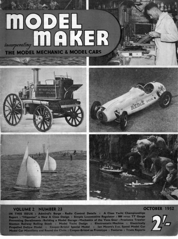
- British Empire Open A Class Championship, By D.J. Laidlaw-Dickson
- Hippotas, A New A Class Yacht, By John A. Lewis
- Fist Steps in Model Yacht Design, By H.E. Andrews
- A. Wilcock – On Mechanics of the Vane Gear

METROPOLITAN } :
[t was not until the last board of the last heat that Yeoman established a two point lead over Scamp to win the British Empire Open A Class Championship at Gosport on Saturday, August 16. The final heat began with Scamp leading by one point, so that Yeoman had to win, and Scamp British Empire HELD AT GOSPORT I1/I8TH AUGUS#® had to lose for the lead to change. Yeoman sailed first and won comfortably, leaving Scamp against the stern competition of near-leader Mouette. The latter won and left the owner-skippered, built and designed Yeoman to take the cup back to Birkenhead for the first time in the history of the event. That old veteran Flame was a worthy third and might easily have notched another victory to add to her forty odd firsts; quite what this boat has, no one can say, but after nearly twenty years it can still take on the best of modern beats in spite of its admittedly “long-way-after’’ Alexander construction by Larry Dawson when a lad of seventeen. Saat A number of new boats made their appearance in this year’s contest, including Vito from Denmark, sailed by last year’s winner, Kai IpsenIt failed to repeat Revanche’s performance last year at Fleetwood and did not qualify for the final. It was a beautiful boat, but the skipper may have lacked experience of its eccentricities under lake conditions, for Danish sailing is for the most part in open water. Most interesting of the newcomers was Lynx, designed by H. B. Tucker, and sailed by D. Macdonald of Y.M.6m.0.A. This was the lightest boat in the contest at 45 lb., with the narrowest beam at 124in. and suffered a displacement penalty in consequence. In light airs it was superb and sailed away from hand faster than anything on the lake. It sported a set of sails in light crinothene, a substance in heavier gauge usually associated with lampshade making, but apparently highly suitable for yacht sails, though not pure white, but a shade of light yellow-cream. Vanity Fair entered by J. Meir of Birmingham and built by Levison to the late Howard Nash’s Fantasy IT design, adds yet another to the Fantasy fleet, others being E. Marsh’s Grenadier and D. Pinsent’s Psyche with, of course, the original Fantasy I, still in the capable hands of N. D. Hatfield with a great London reputation. Vanity oo Top. B.H. Priest (r.) and mate Edwards with winning Yeoman. Above: Moonraker and Yeoman. Below: Reveille and Highlight. Fair appears to display slight modifications from the other Fantasy boats, notably in the sheer, but the builder claims that this is exactly to the 652
original design, and may be a trick of painting that gives this appearance. Most courageous entrant was undoubtedly R. Eland of the recently formed Exeter Club, with his City of Exeter, the first A Class boat from that part of the world, which proved far too pen A Class Championship RertonR TED “BY .D. 4. LAIDLAW-DICKSON “iy sluggish for the class of sailing it was up against and failed to collect a single point in the divisional heats. However, its owner has gathered a fund of useful information on building and sailing, and we hope to see him back again next year with a more formidable craft! Mouette, skippered by A. J. Clark of Bourneville, was interesting as a design of that great model yachtsman, the late W. H. Davey, and was always dangerous—in effect her last-minute victory over Scamp was the decisive factor in putting Yeoman at the top of the list, and could have won herself with a few more points in the last half dozen boards. Major G. B. Lee had the only other skipperdesigned boat in the final with his Reveille, built some ten years ago. In light airs this boatis still capable of a good performance, but a spate of lost boards on the first day made her chances remote, and perhaps discouraged her skipper. Sailing conditions through the week were nearly ideal though, of course, not suited to every boat. For the finals the wind freshened until spinnakers were very much in evidence nicely filled. The increasing use of colours for these sails gives a pleasing air of Cowes. All that is needed is a nice blue and white striped sail, or a Bluebottle blue mainsail to complete the picture. All boats in the final carried Vane gear, in a variety of designs, from the very simple to the extremely complex, one or two with additional Braine attachments to work in conjunction. One boat—in the earlier heats—had a balsa and tissue covered feather for lightness, like a model aeroplane wing. Kai Ipsen’s Vito had a particularly neat and simple layout of Vane, as had winner Yeoman and, of course, Scamp. These are illustrated on another page. By courtesy of the finalists we include a table giving comparative data on all boats, in respect of L.O.A., L.W.L., weight and sail area of top suit, together with designers. It will be noted that Admiral Turner had no less than five boats sailing, with Alexander two, and the rest made up of single designers. It is encouraging that a com- Top: General view of boats and crews at the lake. Above: Davey-designed Mouette and winner Yecman. Below: N. D. Hatfield’s Fantasy and P, G. Bird’s Prelude, which did not quite get into the final 653
MODEL MAKER paratively recent boat should have won, particularly as it was an “‘own design” by the entrant. Had Flame won, as well she might, we do not know quite where our leading designers would have hidden their faces! Our old friend, H. Boussy from France, was over again with Zef, but failed to reach the final. Indeed, there were many such surprises, such boats as the fancied Fantasy, the Daniels-designed Jane, and Littlejohn’s first A-Class design, Arabesque, all failing to go the final stage. Racing throughout the meeting was exceptionally keen, many boards going by a length or less, with three dead heats. Some of the boats which had gone well in the divisional sailing failed to continue in that strain, leaders Moonraker and Helos toth failing to find their form until Saturday by which time they had dropped too far behind to catch up, but none will- disagree that the winning boats were all deserving of their places. Organisation throughout was excellent, and visitors will have pleasant memories of Gosport hospitality, and the hard work put in by the officials in ensuring the success of the meeting. No. | Name Owner 637 530 471 661 YEOMAN SCAMP FLAME MOUETTE B. L. E. A. 611 ESTELLA R. A. Jurd 676 MOONRAKER | 681 | LYNX 656 HIGHLIGHT 580 HELIOS 679 VANITY FAIR | 642 WILDFIRE 520 | REVEILLE H. Priest K. Corrooin L. Dawson J. Clark P. West D. Macdonald L. Davis W. Douglas J. Meir L. Paton | Designer LOA LWL Wt. B. H. Priest Alexander Alexander (mod.) W. H. Davey (late) S/A_ 79 | 544} Sit | 1510 75.95 51.55 48.8 1629 71 5it 50i 1725 84 534 54 1623 Turner Turner | H. B. Tucker Turner | Turner Howard Nash (ex “Fantasy II”) Turner | | | Major G. B. Lee | Lee 79 76 54 53.4 425-154 672 | =55t 803 | 554 79.5) 54.6) \ 684 | 54.9 | | 82 | 654 Div. | 63 | 1646 45 58 622 53 | 60; 65 542 | 544 M|> A A B A B25 1673 oye 1570| 1514 1612 1535 B A A B 1581 A 1560 | B T 15) > Hs | 15 | 23 | 16 | 14 8 | 17 | W th F | s | 174s e832 13 | U1 | 37 | 3I 20 | 12 | 32 | 314; 18 | 14 § 32 | 29 13 | 18 9126 34 | 22 | 10 | I5 | 13 | 37 | 194) | 12 | 12 | 10 | 18 | 27 10 23 8 17 § 27 18 31 8 8 | 27 25; 5/15 | 12) 18 15 | 20 | 13 21 17 | 2 | I | | | | 2¢ 26 244, 33 9425 | 204) 5 | 20 Pts 70 634 él 60 564 56 53 Sik 51 454 25
October 1952 Left-hand page: Top: Kai Ipsen, 1951 winner from Denmark with his Vizo, and on right French competitor Mons. Boussy. Bottom left: Vito and Helios 4 in a qualifying round. Next, Estella and Scamp. Right-hand page: Top, the Levison-built Howard Nash boat Vanity Fair, sailed Next, non-qualifiers by J. Meir. Marian from Felixstowe and Pandora, a Newcastle boat. At the bottom, Scamp and Flame, and L. K. Corrooin and mate adjusting Scamp on the lakeside. NON-QUALIFYING No. Name 356 FANTASY 671 649 664 623 654 531 673 604 F24 581 603 J. Anderton M.Y.S.A. SCHEHERAZADE W. E. Baker PANDORA 464 476 504 645 559 615 684 RHAPSODY CHARM KIT LANCER Il FIORA PRELUDE CITY OF EXETER | | | Club ARABESQUE ITO 682 | Y.M.6m.D.A, MARIAN D35 Owner N. D. Hatfield GRENADIER PSYCHE THISTLE JANE BLACK EMPRESS ZEF TINKER BELL yo F. Shackleton E. Johnsen J. F. Craker Felixstowe Denmark BOATS | Div. | |} || R. F. Tatchell Cc. M. Smith R. Gardner F. Knapman A. McGruer P. G. R. Bird R. Hand London Y.M.6m.0.A. Gosport Fleetwood Helensburgh Nelson Gardens Exeter E. Marsh D. Pinsent J. Lapsley Birkenhead Paignton Nottingham 1) | N. Liverpool \> R. S. Hawgood R. Bradley H. Boussy R. Wells H.N. Amliot Danson Bolton France Portsmouth 600 622 415 PREVAIL MAVOURNEEN RADIANT P. Buchan K. E. Phelan S. Nicholls Aberdeen Hove and Brighton Harwich and 477 461 COLIN EVENLODE F. Shackleton G. Matthews Bradford Ryde Dovercourt 655 J | | Ww 29 6 10 | z | 22 B a 1 16 17 12 0 13 3 7 2 0 12 10 22 12 13 13 9 0 10 19 10 20 8 I il 10 10 10 A | | 4 8 i ee ed | Newcastle Portsmouth M 15 16 12 12 18 et | 20 is} 14 6 16 13 10 13 7 8 3 6 7 2 Th Pts. 6 47 6 46 ea. eee > | 51 47 iret It 10:-| 5 4 15 3 7 0 =10 12 8 5 8 13 0 42 39 37 36 31 31 = 8 is 12 5 9 15 10 51 48 46 13 4l | 8 9 7 16 8 2 5 3 ‘see 3 7 7 12 lo 0 7 7 8 3 3 45 44 44 43 42 4l 39 35 32 31 14
MODEL MAKER HIPPOTA AONE > ‘A’ YACHT by J. A. LEWIS ‘THE A Class rule is perhaps the most interesting in cubic inches in full racing trim. The quarter beam length is measured in a line parallel with the middle fore and aft vertical plane at a distance from it equal to one quarter of the load water line beam and one tenth of this breadth above LWL. The excess of QB one under which to design a boat. It may be thought at first glance that there is not much scope for a designer to develop his ideas, but although the rule is framed to prevent freak boats being produced, there is plenty of opportunity for variations in design. Basically the rule is as follows: Lx +/S LYS x =. 39.37 4 12” D Where L = Load water line in inches plus half any excess in quarter measurement is the amount by which the QBL exceeds the length allowed without penalty. This length is equal to a percentage of the LWL length found by subtracting the square root of half beam ¥/D = the square root of the total sail area in square inches in accordance with regulations. the LWL length in inches from 100 (Percentage = 100—+/4 LWL). There are displacement limits, draught limits and freeboard limits, but the above states the salient features of the rule. Anyone becoming measurement. =~S_ GEASS measured I.Y.R.U. interested in A boats for the first time should obtain a full copy of the rules from the publications secretary of the M.Y.A. It will be seen that the main controlling in- the cube root of the displacement ! A-CLASS YACHT ‘HIPPOTAS’ DESIGNED BY | | APPROX. ¢ OF MAST. mas JOHN.A.LEWIS (2/6 ) MODEL COPYRIGHT OF MAKER PLANS SERVICE. ~ $e Sa 4 NG 38. CLARENDON RD. WATFORD HERT: Ss. st ow Ke. 2920″ BL? 6 SS e ~—— — 4 wC S See es se SSE —— La = 4 12 F Is LEAD APPROX 42:0 Les— oH. 6 aa 3 ena ———— ae a —\ = — oa os $f _——a —— 7 670 oT 8 9 0 ” : =
October 1952 fluences are the reduction of sail area with. increasing LWL and the increase of sail area with increase in displacement. The control of the and though I usually favour as heavy a displacement as practicable I quarter beam length is a good device to prevent extreme overhangs and to keep the hull of fairly normal shape. The fact that the LWL length is the main governing factor with regard to speed makes it necessary to decide this dimension first and a study of some of the best recent A Class boats shows a variation between 49 in. and 56in. For the new design, we show 55in. but during the development of the drawing the waterlines have been snubbed back to give a length of 54.4 in. on the water. In order to do this, the profile has had to be flattened where it crosses the LWL. This looks a little unfair but is worth while in the interests of extra sail area obtained. This snubbing also improves the form resistance of the hull and is to be found in many first class designs in the J Class The is 56 set out 12 metre and 6 metre classes. displacement chosen for the new design lb. which lies nicely between the limits in the rules. Although there is no actual limit regarding the maximum displacement, only the figures used in the formula are restricted, SHEET 2 OF 2 A CLASS | y re VE x do not feel that a dis- placement of over 60 lb. to be justified in any model yacht. Herein lies the big snag in the A Class rule for, generally speaking, the big boats have the advantage when racing under the average conditions in this country, but they become too big and unwieldy to handle for any length of time and what should be a pleasant sport becomes hard labour. When a fairly heavy displacement has to be accommodated on a restricted LWL, the trend has always been towards the narrow boat. In the 6 metre class it was necessary to impose a mininum beam. The new boat follows this trend with a LWL beam of 13.5in., which I feel is as narrow as one can go and still maintain reasonably easy buttock lines and a flat run aft which contributes so much towards a fast craft. The keel has been made rather thicker than usual and this eases the burden of carrying the displacement in the canoe body proper. It is hoped that this design may prove itself to be a fast and weatherly craft under all conditions and that it will bring much pleasure to those who may build to it. HIPPOTAS SAIL PLAN Y Sg aeee pai SS as LwL — Ss — Nee \ Wo Os44. LWL BEAM 13-50″ DISPLACEMENT IN SALT WATER 56°22 LBS SECTIONS SPACED $:5~ WATERLINES SPACED 1:07 SAIL AREA I A WORKING DRAWINGS OF THIS INTERESTING NEW BOAT ON CLASSIC LINES BY THE DESIGNER OF THE SUCCESSFUL 10-RATER ‘*HALCEYON” ARE AVAILABLE AT 12/6 THE SET OF TWO FR. M MODEL MAKER PLANS SERVICE, 38 CLARENDON ROAD, WATFORD, HERTS. LINES ARE HALF FULL SIZE, BUT BODY PLAN IS GIVEN FULL SIZE AND SAIL PLAN FOR THREE SUITS TO QUARTER FULL SIZE. 671
October 1952 EST Check.—Now is the time to test (1) the fairness of your work and (2) to see if you are going to get a hull which sails true at all angles of ‘ FIRST STEPS IN. keel. You check (1) by drawing a test bilge diagonal. This is shown at “D1” on “Polaris” body plan and half breadth plan. Strike in similar lines on your body plan and using a slip of paper or a pair of dividers, measure from point “0” to where the diagonal crosses each section line and transfer that distance to the appropriate station line on the opposite side of your half breadth plan. When all the stations are thus marked and you have also marked the fore and aft ends, use your spline and weights and strike in a line through all the spots. This line must be a fair continuous convex curve and no hollows in it can be tolerated. If it is not up to standard, redraw it to a fair curve, but alter it as little as possible. Transfer your amended distances back to your body plan, redraw the offending sections and re-fair the sheer plan and half a breadth plan. We must now digress into a little bit of theory. For many years the reason why some yachts sailed sweetly at all angles of heel, while others developed vices as soon as they heeled, remained a mystery, but about 20 years ago Admiral Turner made an intensive study of this subject and produced his “Metacentric Shelf Theory.” He therein stated that the main reason for vice in a hull was a condition of unbalance between the forward part of the hull and the after part. When a boat heels she puts more hull into the water than she takes out of it. The heeling action causes a shift of the centre of buoyancy down to leeward and produces a “couple” between the heeled centre of buoyancy and the centre of gravity. This enables the boat to carry her sail. If the quarters are full in relation to the shoulders, she tries to put more of her after end into the water than she does forward. This being manifestly impossible, she drops by the bows until the two immersed volumes balance, the centre of lateral resistance moves violently forward and she gripes up into the wind, requiring much helm to hold her on her course. Similarly, if the shoulders are full in relation to the quarters, the stern drops to restore the balance, the centre of lateral resistance moves after and the boat runs MODEL YACHT DESIGN PART III By H. E. ANDREWS buoyancy for each of the trial sections we have so far drawn. Across your body plan draw heeled water lines at “rail down” level. Using a separate piece of tracing paper for each section, trace the full section lying underneath the heeled water line. (Remember your body plan only shows half sections.) On each piece of tracing paper draw the Welch axis as shown in Fig. 6(a). Now cut out and balance each of these sections like you did your trial mid-section. Draw the line of balance on each section parallel to the Welch axis and measure the distance along the upright LWL from the centre line to where the line of balance crosses the upright LWL. Using the line of your half breadth plan as the axis line for this analysis, transfer to each section line the distance you have obtained from your tracings. Some will be on one side of the axis line and some (in mks of the fin) will be on the other, or negative, side. Having obtained all these spots, join them in as fair a curve as possible. The sort of line which should result if your hull is balanced is shown in full line at Fig. 9. You will see that except in way of the fin this line is straight and parallel to the axis line. If the line is like any of the dotted ones in Fig. 9, your hull is unbalanced and you must then choose whether to alter the after end or the forward end. This depends upon which end of the hull you think best. If, for example, the analysis line forward is reasonably straight and parallel, but the line after tends to bear away from the axis, it obviously means that the after end is bad and needs alteration. In this example, the after end ; 3 = a a ANALYSIS 675 CURVES. GOOD & BAD. = pr 7 AXIS LINE eS 1o S| signed to show these faults at the drawing board stage, a much’ less expensive proceeding than finding them in the finished yacht. I do not propose in this series to go fully into this method of analysis, but to test our drawing at this stage, we will adopt the first part of it and for this purpose we must find the heeled centre of eek tal is too full and must be fined down, particularly off the wind. Admiral Turner’s system of analysis was de-
MODEL MAKER above the LWL. Do not, however, do it violently. Probably a small change on each section will achieve the desired result. When you have made these alterations, repair your drawings and again test for balance. The design ‘‘Polaris” is not absolutely balanced on this system because I thoughteit desirable to sacrifice a small degree of balance in order to obtain qualities which should enable her to plane down wind more easily. Before continuing, I may as well explain the meaning of the curved dotted line running across the sheet plan. This is the “line of rake of the midship section.” You will notice that each buttock line has its point of greatest depth on this line, the inner ones being farther forward than the outer ones. Similarly on the half breadth plan the lower water lines have their points of greatest width farther forward than the upper ones (except on the fin). The purpose of this is to achieve a 3. gives us our displacement and centre of buoyancy, but also gives an idea of “‘rate of change of form” along the hull. To make and use a curve of areas, proceed as follows: line up a page of a notebook, thus— but at this stage you can only complete column 1. Col. | | Col. 2 Section | HI. eocoe Be eh gs 5 This We must now return to your drawing. When the balance line is to your satisfaction you can continue to fill your remaining sections, buttock lines and water lines and diagonals. Continue the process as already explained, taking care to make all your intersections accurate and fairing each line. You should not now be able to go far wrong, and each line should fall sweetly into place. Continue until all the hull lines are drawn and satisfactory. The fin now requires attention. You will notice that the fin water lines are drawn on the sheer plan and not on the half breadth plan. To draw these, first mark on the relevant water line the half breadth of the fin on the mid-section. This is obtained from your body plan. Then using your spline, strike in a fair streamlined curve from forward to aft along this water line and passing through the spot of greatest width. Now do the same for all the other fin water lines, taking care to make all the curves of similar type. Having done this, transfer all the fin water line widths on to your body plan and draw in the section lines for the fin. Calculations —The drawing of the hull is now almost complete and only one important line is missing, the lead line, and before we draw this we must find our yacht’s weight and her centre of buoyancy. Firstly, three important facts :— 1. Lead weighs 0.42 lb. per cubic inch. 2. Fresh water weighs 62.4 lb. per cubic foot. | areas | es 3 Col. 3 | Col. 4 4+ Hull No. long flat “run” to the boat which is conducive to fast planing down wind. You will notice that the forward sections are somewhat sharper than the after ones. causes the slight degree of unbalance. Salt water weighs 64 lb. per cubic foot. To find how much our boat weighs, we have to find how much water she displaces when she floats on her designed L.W.L. We achieve this by constructing a “curve of areas.” This not only -| 115 | 2:53: 1 6 2.92 (MS) 7 2.95 8 9 10 11 12 T 2.53 1.96 oy 66 19 NIL + Fin I> AS 1.16 43 | | ra | at | | areas | =a) Col. 5 c/a areas Totals =O! 406 56 5) t 532 3132 4.436 SaBo tJ 7.81 7.45 4.845 tS 1.845 8i 7.81 TS $89 125 41.522 Now return to your body plan, and counting the squares find the area enclosed by the centre line, the LWL and the section line. Do this for each section and write the answer down in Col. 2 of your notebook as shown (we are using *“ Polaris” as an example). You should take care to obtain separate figures for the hull and the fin. (Co. 3 shows the fin areas.) Having obtained the figures for all the sections, you are now in a position to draw two curves of areas, one for the hull and one for the fin. Take your second sheet of graph paper and draw on it a line equal in length to your LWL. Erect on it section lines corresponding to the section lines on your sheer plan and number them the same. Now mark on this line the forward and after ‘ends of the water line joining the fin and the hull. Using the figures in Col. 2 of your notebook, mark up on each section line the number of inches corresponding to the figure you have (only remembering all the time that your column of figures is square inches). When you have marked all your sections thus, use your spline and weights and draw a fair curve through all the spots, starting and finishing the line on the LWL ends. 676
Ave WiILEOCK-@N centre-pop soldering iron, minor metal saw and files. As mentioned in the previous article, freedo m of the rudder is the first requirement of efficien t vane “centre pop.” To do this perfectly, a lathe is the f te author happens to be a professional answer but a quite satisfactory job can be done engineer; he was before that, and still is, a handy man. He is aware that while there are many very capable engineers, amateur and professional, amongst the model yachting fraternity they are in a minority and the real requirement of information for the majority and suggestion within by the eye and the hand drill. If a hollow tube post is used suitable plugs soldered in provide the necessary solid ends. The accuracy requiredis that necess ary to avoid the post making contact with the trunk during the capabilities of the handy man having only hand tools. These notes then are directed to him. So far as possible operations will be limited to the following tools, although reference will be made to others for more advanced metal workers: Screwdrivers, pliers, hand-drill and twist drills, | | steering. This is most readily achieved by “swinging” it on pivot points at both the top and bottom. Fig. 1 clearly shows the top and bottom mountings. Where the rudder post is solid the conical cavities top and bottom can be drilled Straight out using a spear point or careful ly sharpened twist drill, following a carefully placed any part of its movement. For those having suitable tape and dies the arrangement of Fig. 2 is good even if a little unorthodox and gives a slightly clearer deck. It cannot be recommended where a quadrant js fitted to the rudder post having strong pulls applied. This same arrangement can be applied to the pintles of the vane mechanism. The fitting for the top of the rudder post is shown in Fig. 3 and in general arrangement probably cannot be beaten. It is simple, light, and gives a clear indication of the positio n of the rudder below when making adjustments or watching the boat in action—providing it is securely fixed to the rudder post—and enables ALTERNATIVE ACROSS | WITH | BOAT LOCKING INSTEAD BRIDGE OF NUTS TAPPED HOLE | | >— RUDDER POST THREADED both’ a centring line and counterweight for balancing to be neatly fixed. Three methods of securing the tiller to the rudder post are shown in Fig. 3 (a), (b), (c). The first (a) using two grub screws through the collar are in the author’ s opinion the best as this arrangement can be very secure but can be dismantled easily. The necessa ry drill and tap may not however be available. The second method (b) is again good and the tapped STEADY PIN IN CLEARANCE hole can be avoided by using a nut and bolt. The third method (c) is that using solder should be secure, it is not so convenient and occasio ns have been known for the soldered joint to fail during the course of racing, when little can be done about it. It is essential in any case that the collar should be a snug fit on the rudder post. Do not be satisfied with anything sloppy. Turning to the vane mechanism, the vertica l pintle with top point bearing holds sway, since if the mechanism is balanced in the locked 678
October 1952 Meehaniecs of the Vane Gear position, i.e. non-self tack position, it is balancing on the point and there is little side thrust at the base, nevertheless POSITIONS FOR GOUNTERWEIGHTS FOR BALANCE jit is worth while reducing | wh friction as far as possible by one of the arrangements shown in Fig. 4 (a) or (b). To reduce the pintle diameter as shown in Fig. 4 (b) is really a job for a lathe, since the reduced section is for clearance only it can be quite satisfactorily filed FILLET OF SOLDER. POST & COLLAR TINNED BEFORE ASSEMBLY 4 away. A similar clearance is desirable on the self tack pintles where these are as shown in Fig. 4(c). The linkage between the tiller and the vane may now be considered. This connection probably gives rise to as many mechanical and operational difficulties as any part of vane steering. The Ny N NY s s NY s s Ny 3 NY s ‘ ‘ ‘ NY > 5 NY HN) s N N arrangement and proportions most frequently seen are shown in Fig. 5 in simplified form. s N The length of the tiller arm is limited in length by requiring to clear the vane pintle and in order to obtain as large a rudder movement as possible, the connection pin is placed to be well forward in the tiller arm with the rudder in the “rudder VANE SELF TACK LEVER sdocnetietuce BASE BAR neutral position.” This gives rise to two faults, (1) the leverage that the vane can exert on the rudder is too small and (2) when for any reason the vane has swung through a large angle the water pressure on the rudder exerts a binding action between the tiller slot and connection pin. Experience suggests the following: A tiller arm to just clear the vane pintle as mentioned above and the pin fixed in the vane base to be between 4 and 4 the distance between the vane pintle and rudder post from the vane pintle. This gives appreciable leverage on the tiller arm, for small angles of movement, so that the limited power in the vane is capable of moving the rudder early. It limits the maximum rudder movement to some 20° to 30°, but this is adequate if the sail plan is correctly placed over the hull and the boat is not being sailed overcanvased. The limited tiller arm movement avoids jamming or binding which is a great advantage. Turning to the self tack mechanism of the vane. The self tack feature is used when sailing against the wind and as close as possible with speed on both port and starboard tacks. The angle required lies between 40° and 45° and when once found can be almost fixed. It is essential that there should be no tendency to “lock” up to that Typical vanes seen at “A” Class Nationals at Gosport this summer. Heading on left depicts Kai Ipsen’s delightfully simple yet efficient design. On the right, upper picture, shows winner J. H. Priest’s vane as fitted to ““‘Yeoman”; and below, that fitted on second boat “Scamp” 679
a MODEL MAKER CENTREING from the central vane pintle to the centreline of LINE RUODER POST BEST POSITION FOR VANE the vane a minimum of 4 in. for a Marblehead and 5in. for a 10 Rater—very much shorter distances are observed to be the rule with the uninitiated. If such distances cannot be tolerated even by moving the vane pintle to the stern of the boat then at least approach as far as one can. Since the counter-weight arm and weight must equal in weight and centre of gravity it must of necessity be similar in length. The proposal to possibly move the vane pintle to the stern of the boat may raise the problem of distance between the rudder post and the vane pintle. Fig. 6 shows a very efficient method of overcoming the difficulty. It is efficient because, unlike the pin and slot linkage, over the movement range used, it will maintain a reasonably constant ratio of angular movement between the vane and rudder. A two to one ratio as shown will be found to be satisfactory. The disadvantage of the scheme is trouble of balancing. This it will be PIN PINTLE WITH PLAIN SHANK OR FREQUENTLY OBSERVED POSITION OF PIN COLLAR CYCLE SPOKE WITH EYE BENT TO MATCH SHANK eee COUNTERWEIGHT ON SCREW exo] CROSS SECTION found can be effected by a small counter-weight in the position shown and should be adjusted with the yacht keeled in the water with the vane emails CROSS SECTION superstructure removed. Finally, mention must be made of the vane feather. This must be as light as possible while being strong enough. Since a counter-weight equal to it has also to be carried, the weight of the whole must be kept as low as possible. Balsa or Obeche are most appropriate materials. To angle and to meet this condition where a pin and slot arrangement is used it is essential that the pin be on the vane lever and the slot on the enable the size to be reduced while improving the power and also strengthening the feather, the fitting of a stabilising fin or fins as shown in Fig. 7 (a) or (b) is recommended. This will in most cases enable the area to be reduced by up to 50%; the reduction being made in the width, it is important to maintain height. An advantage of getting the vane well astern is that it moves the feather into an area less disturbed by eddies from the mainsail. counter weight lever. The length of the slot, as for the tiller arm, should be such as to clear the other pintle and the pin should be positioned so that for a 45° movement of the vane, the counterweight moves through an equal angle. Thus over the small range of adjustment (40°-45°) required the angular movements of vane and counterweight will be comparable and the gear can be balanced. With the pin and slot mechanism it will be found that the angular movement of the vane and counter-weight arms differ considerably and the above adjustments are necessary for good operation. The use of gears enables the angular € VANE SELF-TACKING GEAR By K. P. MORRIS movements to be always equal and when properly engaged gives a movement less liable to bending. Consideration must be given to the length of the arm carrying the vane. The vane is normally ee a OTHER RECENT ARTICLES ON GEARS IN “MODEL MAKER” VANE March, 1951 A NEW VANE STEERING GEAR By S. ELPHEE June, 1951 (Available through MODEL MAKER Plans Service at 1/6) flying in the wind and moves, or should move for slight deviations of the boat or wind. The area presented to the wind is very small and the power is similarly small. To make the most of a small power it requires applying at the end of a long lever. The length this lever can be of a vane gear is obviously limited by the position occupied in the running position. Suggested lengths are, VANE GEAR COMMENTARY By A. WILCOCK April, 1952 A LIGHT VANE GEAR By J. H. CUNNINGHAM, M.I.Mech.E. September, 1952 (Available through MODEL MAKER Plans Service at 2/6) 680


