- Editorial — Marks the start of a new volume, discusses developments in model yacht classes (especially 10‑raters, 6‑metres, and the 50‑800 class), and reports design experiments improving sail balance.
- M.Y.A. Council Meeting & International Racing — Summarizes key decisions, including the creation of a committee to oversee the Yachting Monthly Cup and future international racing conditions.
- Masts and Spars (Circa 1790–1815) — Explains historical construction of masts (including composite “armed” masts) and their proportions, fittings, and placement.
- Building a Planked Model Yacht — Continues detailed guidance on preparing drawings, backbone, keel, and templates before beginning construction.
- How to Make Model Ship and Steamer Fittings — Provides instructions for building detailed fittings such as binnacles, compasses, and steering wheels, with practical modeling techniques.

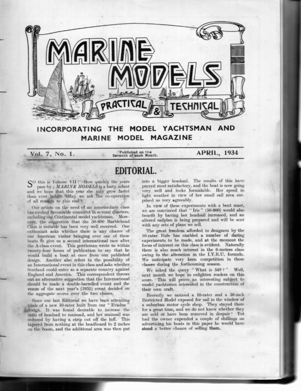
ta UH Capps LL am) )\NINN)YNYOYVINNNYYDDIDDI NINN +1) INCORPORATING THE MODEL MARINE Vol. 7, No. 1. MODEL YACHTSMAN AND MAGAZINE Published on the Seventh of each Month. APRIL, 1934 +. EDITORIAL. O this is Volume VII! «How quickly the years pass by ; MARINE MODELS is a lusty infant and we hope that this year she may grow faster than ever Hefei. WMay we ask the co-operation of all reatiafs to this end? ° . Our artiele on the need of an intermediate class has evoked favourable commént in several quarters, including one Continental model yachtsman. Moreoyér, the suggestion that the 50-800 Marblehead Class is suitable has been very well received. One enthusiast asks whether there is any chance of our American visitor bringing over one of these boats fo give us a second international race after the A-class event. This gentleman wrote us within twenty-four hours of publication to say that he would build a boat at once from our published design. Another also refers to the possibility of an International event in this class and asks whether Scotland could enter as a separate country against England and America. This correspondent throws out an alternative suggestion that the International should be made a double-barrelled event and the venue of the next year’s (1935) event decided on the aggregate scores over the two classes, Since our last Editorial we have been attending trials of a new 10-rater built from our “ Evadne” Saesign. It was found desirable to increase the ratio of headsail to mainsail, and her mainsail was reduced by having a strip cut off the luff. This tapered from nothing at the headboard to 2 inches on the boom, and the additional area was then put into a bigger headsail. The results of proved most satisfactory, and the boat is very well and looks formidable. Her light weather in view of her small sail this have now going speed in area sur- prised us very agreeably. In view of these experiments with a bent mast, we are convinced that “Iris ” (50-800) would also benefit by having her headsail increased, and an altered sailplan is being prepared and will be sent with any sets of plans we sell. The great freedom afforded to designers by the 10-rater Rule has enabled a number of daring experiments to be made, and at the moment the focus of interest on this class is evident. Naturally there is also much interest in the 6-metres class owing to the alteration in the LY.R.U. formula. We anticipate very keen competition in these classes during the forthcoming season. Well, We asked the query “ What is 549?” next month we hope to enlighten readers on this an interesting subject to score. This will prove model yachtsmen interested in the construction of their own craft. Recently we noticed a 10-rater and a 36-inch Restricted Model exposed for sail in the window of a suburban motor cycle shop. They stayed there for a great time, and we do not know whether they are sold or have been removed in despair’ Yet had the owner expended a couple of shillings on advertising his boats in this paper he would have stood a better chance of selling them.
yA M.Y.A. COUNCIL MEETING. A Special Council Meeting was held on March 1, with A. J. Hugo in the Chair, supported by Messrs. Adams, Bauer, Cooper, Feltwell, Hill, Littlejohn, Mamber, Munro, Pike, Simmonds, Tucker and Webster. After disposing of the Minutes, and before other business, the election of the Llandudno M.Y.C., and R. S. Momber (of Cambridge) were unanimously approved. The Secretary reported that the Donors of the the nominated Permanent Committee to control the future conduct of the International Races for the Cup—with confidence that the decisions reached would be in the best interest of the Sport and of the M.Y.A. The personnel of this Committee are: Wm. M. Carpenter (Birkenhead) acting as Secretary and Treasurer for the Committee, H. J. Marsden (Fleetwood), J. G. Feltwell and C. an, Chairm M.Y.A. the with n), (Londo Adams Treasurer and Secretary (ex officio). The preparation of Notices and other information Yachting Monthly Cup had been pleased to approve l respecting this year’s Selection and Internationa all to issued be y shortl will ood Fleetw at g Racin concerned. On the same subject a Resolution was tabled by Mr. Tucker—the purpose of which was to com- l pletely reverse the decisions of the recent Genera taken was le possib de attitu only the and Meeting, order, by the Chairman, who ruled the motion out offorwar d without entering into the reasons put in the motion. Mr. Stewart had entered an objection to adoption as of provision which permitted the Bipod Mastied being quite the opposite of the intentions embod found in the I.Y.R.U. proper. Here, again, it lwas g, impossible to go against the Genera Meetin d ordere ore, theref were, Rule of tions Altera and the to be issued as passed. Certain other suggested amendments of Rule were to hand and were referred to the appropriate Committee. d A Permanent Committee on Rating Rules (agree deal to at General Meeting) was now appointed to any with any relative queries and to keep watch on should future changes in the LY.R.U. Rules. Thision, and lead to more efficient and prompt attentas applie d ensure that our Rules are kept up to date to models in the respective classes. The usual Emergency Committee was also appointed. Registration of Yachts was a subject which is important to all—for it had been found that irregularities had crept into practice, and ther Council instructed the Registrar to issue no numbein till a yacht had been duly measured, foundduly rating, and declared by the Club Secretary or appointed Measurer—and that the existing Rule be rigidly followed. The very interesting film of the 1933 Y.M. Cup 2aces at Fleetwood has been reproduced with club the object of loaning it for exhibition at Hon. the to ation applic on ars rticul functions—pa Secretary. The propriety, or otherwise, of Sunday Fixtures was raised under Correspondence—when two letters were read, The Council gave sympathetic conon sideration and are prepared to review the questibut when dealing with next year’s Fixture List, ing were quite definite on the inadvisability of chang published dates because many programmes had already been arranged accordingly. l points of detail affecting administration Severa the General were dealt with, mainly,arising from the meeting Meeting and Change of Officers—and closed with a vote of thanks to the Chairman. A. LITTLEJOHN, Hon. Secretary, M.Y.A., 124, Fitz-Neal St., London, W.12. “ YACHTING MONTHLY CUP.” FORMATION OF NEW COMMITTEE OF CONTROL. after the original Cup had been won In 1926, Monthly outright, the Proprietors of Yachtling tition, compe ationa Intern for Cup er anoth ded provi which under ions condit of set a and published it was to be competed for in future. ng In 1931 a deed of gift was prepared,thismaki deed as but ., M.Y.A the to Cup the over never formally embodied altered conditions it was sion has arisen confu and ., M.Y.A accepted by the conditions in some quarters as to which set ofunder which are now binding, viz. : those of 1926, 1931, of those or ted, accep been s alway have s entrie the to. as tion defini ent differ a ined which conta right of entry, as well as other alterations. s, viz.: The matter was referred to the Donor who were the Proprietors of Yachting Monthly, in the but on decisi ary arbitr an make to ed prepar ing follow the rd forwa put rights exercise of their proposals for the consideration of the M.Y.A. :-—
Yachting Monthly Cup be That the handed over to a new body, especially formed for the future control of the Cup ; this body to be composed of representative persons suitably chosen to represent International Model Yacht Racing, who will decide the conditions under which the Cup shall be competed for. That the M.Y.A. should nominate a body of not less than 4 nor more than 7 Model Yachtsmen resident in Great Britain, ‘who are members of Clubs affiliated to the M.Y.A., for the purpose of controlling the Yachting Monthly Cup in future. That the Cup shall be, or become, a Perpetual Challenge Cup, and shall continue to be known or referred to at all times as the Yachting Monthly Cup. That the M.Y.A. be empowered to fill vacancies which may occur in this body from time to time. The new body to be known as the “ Yachting Monthly (British) International Racing Committee.” sailed under the 1926 conditions, and the new not later than February 28, 1934. In order that adequate notice maybe given to all concerned the 1934 race to be to apply W. Chairman, Hon. Secretary, and Hon. Treasurer, (Ezx-officio). Hon. Secretary-Treasurer, M.Y.A. Wm. M. Carpenter (Birkenhead M.Y.C.). Other Members, J. G. Feltwell and C. H. Adams (Y.M. 6m. O.A., Surbiton) ; J. Marsden (Fleetwood M.Y.C. ). The has above been nominated duly accepted Committee and of approved Control by the Donors. It was further agreed that any expenses incurred by the Committee for postage, printing, insurance, Cup replicas, and incidentals should be reimbursed out of the Yachting Monthly Contingency Fund. Notice of any alterations in the conditions and any other necessary information will be furnished by the new Committee in due course to all countries In the meantime, all correspondence relating to—and entries for—the International Xace should be addressed to the Hon. Secretary of the Committee, Wm. M. Carpenter, 131, Shrewsbury Road, Birkenhead, Cheshire, England. M.ig@arpenter’s manifesto.—Editor, M.M. THE CHAPMAN LIGHT. 1935 of the new Committee :— As the Official Organ of. the Model Yachting Association, we refrain from comment on Mr. to These proposals were approved by the M.Y.A., at the Annual General Meeting, held January 27, 1934, and the following were nominated as members concerned. The Committee to be formed and in: being arrangements and future years. From an original Drawing by G. W. Munro.
HOW TO MAKE MODEL SHIP AND STEAMER FITTINGS. (Continued from page 306). hts, I yeee I was on the subject of skylig of glazing these. should have referred to methods local Very thin glass must be used, try your these slides, copic micros old some get and st chemi is not are always of very good clear glass, celluloidafter to be recommended as it becomes yellow le sorta comparatively short time, the non-imflamabnothing may be better but even this discolours, and can be found to beat real glass. An easy way to glaze is to fretsaw out your frame t this complete with one long rectangular slot,torabbe depth the chisel tiny a with inside the on round all in equal to the thickness of the glass, cut theor glass a glass one panel to size with either a diamond includ es a cutter. Note! that if your workshop edge of the hand power emery wheel grinder the ed to fit the reduc ly quick and easily be glass can frame, but do not press too heavily on thes emery wheel or glass may splinter and your finger suffer. with Be careful to fit glass to frame tightly and made easily be can ows” “wind of r numbe glue, the g these by shaping small pieces of wood and fittin respective by glueing them to the glass in their the length intermediate places and at right angles to of the frame. If the builder is a clever craftsman he may, of in course, make up each “window” separately and is made, exactly the same way that a real skylight be but even if his scale is fairly large it will found to be a tricky job, and it will save time to take the trouble to make a little jig or two. Do not be afraid of getting glue, varnish or paint on the glass as when the whole is quite dry and hard it can be easily scraped off with the point of a sharp penknife. By A. P. Isarp, A.M.I.Mech.E. Let us consider now our navigation and control equipment. The binnacle and compass can cither be elaborate. such as like Sir William Thompson’s, complete with electric light, corrector spheres, back and front shutters, clinometer, sights and liquid compass or a plain simple affair being merely a rectangular, box for fixing on any convenient spot such as the cabin-top, containing a plain ordinary compass. The former are to be found in various elaborate forms on large ships, the latter on fishing boats and other small craft. For our purpose we will consider a sort of composition of the two and fig. 27 gives a good idea of this. The column may be turned out of a piece of brass rod with as much metal as possible removed to reduce its weight by drilling almost right through its length; the little compass is probably better bought from one of our many suppliers, or, if desired, it can easily be made. Cut a slice off a thin brass tube whose diameter is to be the diameter of the required compass, and with a length equal to about half its diameter, face off both ends truly. Stand this on a small piece of flat brass»sheet, which “you have already heavily tinned, hold if in a flame until the solder runs and allow to cool, then neatly trim off the edges. You now have a little brass cup or box. Turn it bottom up, find its exact centre and drill a tiny hole right through the bottom. Get an ordinary sewing needle and insert its point upwards through this tiny hole until the needle jams tightly in the hole. The point of the needle should now project inside the cup or box about half way up. Carefully break or nip off the needle, leaving the point in box, and touch with a hot soldering iron on the outside to fix the point or pivot. Take a piece of good white paper and on your drawing board describe a circle just smaller than the inside diameter of the little brass box and mark this off into eight parts (see fig. 27a), putting a dot between each as shown. Indian ink is the best thing to use for this and a fine pen. Now take an old razor blade and soften this by FIG.17& heating to a red heat and allowing to cool slowly. With a sharp and acute centre punch make a slight centre pop in a suitable position, and with a pair of very sharp pointed compasses, and using this centre pop, describe a circle exactly equal in diameter to your compass card (fig. 27 a). Now carefully break, cut and grind out your compass needle to the shape shown in fig. 276. Then polish up the little needle on both sides.
You must now magnetize this little needle, and this is done by merely stroking it about a dozen times, from one tip to the other, with one pole of any permanent magnet that you may possess, but note carefully that the strokes must always be in the same direction and slow, never backwards and forwards. Now take the compass card and turn it upside down and with good glue, such as Croid, stick the compass needle down flat across it with the hollow of the little centre pop upwards. When dry and set, turn it right side up and drop it into the compass box so that the point of the pivot goes into the It is hardly necessary to describe speaking tubes (fig. 28), which are to be found on the bridge. They can be made from small odd pieces of suitable diameter copper tubing, one end of which has been ‘ belled ”’ out. This is done by simply working a piece of steel wire round and round in the bore of the tube and at a sharp angle. The other end of the tube may then be pushed down into a pre- viously drilled hole in the floor of the bridge-deck, or elsewhere, as desired. They should be highly polished and lacquered all over. centre pop of the compass needle. The little card should now swing on its pivot and your compass is complete except for a glass disc which can be made in a similar manner to the portlight glasses previously described. Make it a tight fit in the compass box, and if pressed nearly down on the compass card it will prevent same from jumping off its pivot whilst still allowing it to swing. Of course, if you are a good turner you can chuck the little compass box in your lathe and turn out a tiny recess to take the glass. Recess the top of the column (see fig. 27) just to take the compass box nicely and make a domed cap or top to fit over. _Drill*and file this on one side as shown in the figure. This opening, through which the helmsman looks, should be glazed, but this is not necessary, but thétimside should be painted white. An easy way to make this dome is by just drilling out a short piece of brass rod, which has been chucked in the lathe, to just the right size to slide over the top of the column. Then turn the outside all over to shape. An alternative is to press one out from thin sheet finishing off by light tapping with a small hammer. If it is desired to make the fitting a little more elaborate then corrector spheres may be fitted as shown by dotted lines in the sketch. It should be observed that when drilling out the column the base may be left solid to allow for drilling and tapping for a screw to pass up from the underside of the deck or bridge for fixing purposes as shown. FIG.29. We must have a steering wheel, a most important fitting, but the same remarks previously made about other fittings equally apply, namely, that they are many and various in their shapes and design. Fig. 29, however, may be taken as a general type and can be used with equal correctness on a great number of different models. The builder may, of course, elaborate or simplify this as his inclinations lead him. For instance, the wheels to be found aft on sailing ships are of large diameter, while their gearing is more or less of a crude type; on the other hand big ships with their steam, electric or hydraulic steering gears, embodying the very latest engineering practice, are the very opposite from crude. The type of wheel about to be described can be made to work, if desired, by being coupled to the rudder by means of chains, cables or gears. Starting with the column, this can be turned from brass rod by chucking in a self-centreing chuck and drilling right through if the wheel is to be a working model, but sufficient room must be allowed in its head for either a bobbin or a set of bevel gears. The cable or shaft, as the case may be, is taken down through the centre of the column below decks, round pulleys or sheaves, and ultimately aft to the rudder head quadrant. The method of connection must suit the particular case and can be left to the FIG. As. builder to decide. The base of the column is provided with two or three studs situated on its periphery, these pass through the deck for fixing by means of nuts. The wheel itself can either be made of wood or metal, but if of wood the material must be of the
very best and hard, as otherwise trouble will be most certainly met by splitting and cracking just when the job is finished; nevertheless, a nicely finished wheel in wood makes a very attractive fitting. The method of manufacturing would be the same in either case. We will suppose that the builder wishes to make a working model and decides to make it from metal, but if a wooden rim is desired the construction is practically the same. First decide upon the diameter. Select a suitable piece of brass rod, chuck this in your self-centreing chuck and drill out to the inside diameter. Then turn the outside to size and mark with the parting tool where it is to be ultimately parted off. This would be roughly a little less than the depth of the rim. in the boss. If your work has been done well and accurately, all will be well, but if not you may have to wangle a spoke here and there. We mentioned one spoke a little longer than the others. The idea of this is that it serves as a locking screw by screwing well down into the wheel shaft after the wheel has been screwed on to same. Take a short piece of suitable diameter brass rod, through which a hole must be drilled equal in diameter to the diameter of the wheel shaft to serve as its bearing. This must be fixed into position at the top of the column very firmly by being spiggotted and neatly soldered, sce fig. 29 b. To assemble, push wheel shaft with wheel attached through its bearing in head of column. Insert with tweezers (or any other method you fancy) the bobbin or bevel gear wheel and screw right home, adjusting nicely with no end play but allowing wheel to revolve freely. Finally lock with either a small grub screw in bobbin or bevel, or nut on end of wheel shaft and the job is finished, except for a cap. This cap should be removable and of brass fitted to the top of the column. Every separate part should be highly polished before assembly and the whole lacquered afterwards. FIG. 192, Now, with a sharp pointed tool, describe a line exactly in the centre of the rim by simply pulling your lathe round by hand, mark off on this line dividing your rim into eight equal parts, and with a sharp centre punch centre pop these marks. At these spots holes must be drilled with a hand brace for the spokes, but do not remove the rim from your chuck. The size of the spokes should be roughly half the width of the rim and the spoke holes should be large enough to allow the spokes to pass through easily. The holes being drilled, run your lathe at high speed and with a small smooth file just round off the two edges of the rim nicely, put your tool into position and part off. The rim is now finished and can be put aside for the moment. The boss of the wheel is made in exactly the same way, only the centre hole is not bored quite your spokes, which should be turned up as shown in fig. 29a.° The length of the spokes from the screwed end to the shoulder below the handle must be exactly calculated or found by trial and error. It will be noted that the ends are screwed to the derth of the boss holes. Eight spokes will be required, but one of them should be just a trifle longer than the others for a reason that will be obvious later. Now assemble your wheel by taking spoke by spoke and passing each through its respective hole in the rim and screwing it down into its hole FiG.304. The next item of importance on the bridge is the engine-room telegraph or telegraphs. These will not present much difficulty, especially if the builder has made the last fitting successfully. Of course, he may be ingenious and make it a real control to operate his main steam valve sor his electric motors, and, as a matter of fact, neither of these suggestions would be at all difficult, but as it is thought that the majority of builders will not do so, we will consider a dummy. (To be continued). oe through. This hole is to be tapped. The spoke holes are drilled tapping size to suit
HEELING AND pa TOUGH quite a good deal of experimental WIND FORCES. No. 3. Yacht work has been done regarding wind pressures on yacht sails, nevertheless the laws governing these However, it is pressures are still uncertain. aft. question by the use of orthodox assumptions. It is usual to assume that the yacht is upright and that the sails are braced in a fore and aft direction, that the apparent wind is abeam (see fig. 1) and is acting horizontally, and that no angle of leeway fore and aft. possible to arrive at an approximate solution of the We will, however, examine several other exists. conditions and, in all cases, the last three assumptions are understood. No. 1. Yacht upright, sails braced fore and aft. “swung off” No. 2. Yacht upright, boom to leeward. By Detta. inclined, sails braced fore and Yacht inclined and boom “swung off” No. 4. to leeward. No. 5. No. 6. Yacht inclined through 90°, sails braced Yacht upright, boom “swung No. 1. The Total Sail Area (TSA) is exposed to the wind pressure, therefore the Effective Sail (1) a ned Area (ESA) =TSA It is obvious that as the yacht is inclined or the boom “swung off” to lee, this area TSA will be reduced (see figs. 2 & 3). This reduced area is known as the Effective Sail Area (ESA), and is the area used for obtaining the wind forces. AO+ BO COINCIDE WHEN YACHT JS STATIONARY, BO-= DIRECTION OF REAL WIND: 6 Ad= = « (Oz « ARB= ” ~—® APPARENT « « NORMAL 4 © YACHT. A0= WIND ABEAM. C B “ ESA. EFFECTIVE SAIL AREA 7 ‘lESA= TSAcos 30° EFFECTIVE SAIL AREA, whey ESA. | FIG. 2. ESA= TSA cos 35 Y off” 90° to leeward. = ToT SAIL ARE. TS FIG3. 300M SWING
No. 2. (5) a8 ESA sq. ft. =ESA sq. ins.+144 … The Horizontal Force is first obtained, the Normal and Vertical Forces being derived from ESA,=TSA x cosine ofthe boom angle. Most mathematical books contain a table of the Horizontal force. sine and cosine values. No. 3. The Horizontal Force in lbs. HF=ESA sq. ft x. (6) f. ss wind pressure in lbs. per sq. ft. ESA,=TSA cosine of the heel angle No. 4. ESA,=TSAxcosine of the heel angle (4) x cosine of boom angle The Normal Force in lbs. (NF) is the force acting 4). “ square-on ”’ to sail (see fig. =NIL, as edge of sail, ‘only is No. 5. ESA, exposed to wind. No. 6. ESA,=NIL, Normal Force in lbs. (NE)= HF x cosine of the (7) soi ne nee angle of heel… When yachtis upright HF and NF are equal. as edge of sail only is exposed to wind. SAIL PLANE . FIG4. AT 35° FORCES SHEWN GRAPHICALLY HEEL. It is, therefore, possible to find the ESA from the TSA for any angle of heel, any angle of boom or any combination of these. Consider now the effects of the wind on the ESA. The wind exerts a pressure on the sails. The greater the velocity of the wind, the greater is the pressure exerted. Numerous experiments have been conducted to find, among other things, the pressure exerted at various velocities and various heights. Part of the Beaufort wind scale is given in Table 1. The Beaufort pressure values are too high, if applied to model yachts, as the wind, acting at a height of 2 to 3 feet above the water surface, also being filtered in most cases by obstructions around or near the pond sides, reduces the Beaufort values to about a half. These values are given in “ Ibs. per sq. ft.”; it is therefore necescary to have the ESA in sq. ft. ae The Vertical Force of the angle of heel~oa lbs. in. (VF)=NF sine 5 clearer. A model yacht having a TSA of 1800 sq. ins. is inclined through an angle of 35° from the upright ’’ to lee through 30°. and her boom is “‘ swung-off Apparent wind abeam, Fresh Breeze blowing. no leeway. Find ESA, also the HF, NF and VF in lbs. cos 35°=819. cos 30°=866. W.P.=-65 lbs. /sq. ft. x From (4) E.S.A,=TSA > cosine of heel angle cos. of boom angle. = 1800 cos 35° “cos. 30°=1800 x -819 x “866 = ESA,. —1275 sq. ins. From (5) ESA sq. ft. =ESA sq. ins. —1275~—144=8:85 sq. ft. +144 BEAUFORT WIND SCALE. Determined at Coast Station at height 33ft. above Sea Level. Force | Average Velocity Equivalent Pressure in Ibs. per sq. ft. No. in Knots. 4 14 67 5 19 1-3] 6 24 2°30 yi 30 3°60 (8) A worked out example should help to make it | Equivalent Pressure Description of 33 Moderate Breeze Wind. _in Ibs./sq. ft. for Models. | “65 | 115 | | 1-80 | Fresh Breeze Strong Breeze i | Moderate Gale
) to 90° heel, although in actual From (6) HF in lbs. =ESA sq. ft. W.P. in lbs. / sq. ft. =8-85 « -65=5-75 lbs. From (7) NF in lbs.=HF x cos. of heel angle practise it would not be necessary to carry them beyond an angle of, say, 35°. =5-75 x cos. 35° =5-75 x ‘819=4-72 lbs. From (8) VF in lbs.= NF sine of heel angle =4-72 x sine 35° =4-72 x -574=2-72 lbs. In Fig. 4 the HF, NF and VF are shown graphic- As the HF varies as the ESA’s this enables us to find the HF for any angle of heel and any ESA Find ally. It should be clearly understood that the above value, under the above conditions. Ex. HF for ESA of 550 sq. ins. at 35° heel. Fig. 5. At 35° heel ESA=1100 sq. ins. and HF= 4:96 lbs. Therefore HF=4-96 x =2-48 lbs. HF of 5-75 lbs. is merely the force acting upon the sail and is not the cause of the yacht heeling to 35°. To find the angle of heel under a given force The HF also varies as the W. Press. values.* To find HF for any other W.P. value. Ex. Find is quite another matter. The curves of ESA, HF, NF and VF (fig. 5) have been plotted to show the relationship to each 1-15 Ibs./sq. ft. From (fig. 5) HF at -65 W.P. value=5-76 lbs., therefore HF in strong breeze other and for that reason they were StU Yyyy) Veen Ynudiy TOTAL SAIL AREA 1800 Sains. WE heeled 35° strong breeze. W.P.= 65 to |40°Gales | }30°| 30° | L_ |50° |60″he|70° alo |20° [30° ANGLE | 0°Te | 0° Tes MONEL UPRKGHT – SAILS BRACED FORESAFT. WP:-65’bs/sar. WIND ABEAM. [i890 SINE | 0 [174 [-342|-500 1643 [766 [366 [ogo] 935] 1 | (O00 1400 Cosine | | |+985]-340|-366 |-166 |-643 |-Soo }342 [174] 0. | L– ESA= Toi COSHEEL ANGLE «C05 BOOM ANGLE Da HEEL: VE No pte So hy ATASPHEEL VF = SHE] HE = ESAsa rt. x WP inlbs/sq FT. {200 NF= HF x (OS HEEL ANCLE 1 Oy S Lop f 6F A es is i AF Ee BY <2 We LENGE IMMERSED (2 : ee NN VEMAX eee aw VE= NFXSIN. OF HEEL ANGLE. AT GO. ESA= 12 ESA. UPRIGHT. ates se = GH NA pes ATSS° CSA = '2TSA. ~ ee a i000 4 z $0018 z G00}. 400 i"Py * PQ Mm + 0 yacht =5-76 x 1'15=—10 Ibs. extended YY Ye A ong 14 z HF 5 fo 6 0 % 3 % 4 46 D 5S © S&S HD B 8H 8 BH By Devta. EPLYING to ‘Sailor’s” letter in the February issue, regarding ‘“ Boring and Depression,” the following remarks may be of some assistance. * Boring” is principally the result of the Lon- gitudinal Cr. of Buoyancy moving aft when yacht is heeled, and is caused by aft overhang displacing more water than the forward overhang, that is, it is principally due to faulty distribution of buoyancy in a fore and aft direction, but particularly in the overhangs. “Squatting” is the reverse of this but is not such a common fault. However, these defects can be safeguarded against to a good extent, when drawing out hull form or lines, by comparing the relative positions of the L.C.B. and. L.Cr. of flotation when upright and at, say, 30° heel. They should almost coincide. Should they not coincide, having moved aft when heeled, the remedy is to “fine” the aft overhang a little and “fill” out the forward overhang a corresponding amount. The reserve buoyancy of the overhangs is “drawn” upon at the larger angles of keel only. A very small change of form in the overhangs may have the same effect as a larger change nearer midship. It’s purely a question of moments.
——— en SE ee tegarding depression, it’s doubtful if any vertical depression actually occurs in a modern Racing Yacht or model, with her raking mast and curving sails, besides the lifting power derived from a wellmade foresail, placed, as it is, so advantageously, to correct any tendency to ‘“ Bore.” The depression figure of 6 lbs. calls for a little investigation. On working back from 6 lbs. to find the actual Sail Area, certain assumptions had to be made, viz., wind. Fresh Breeze Beaufort Scale—20 knots vel. pressure of 1-31 lbs. per sq. ft. (-65 Ib./sq. ft. for models). Angle of heel 45°. Boom to lee 30°. Sails flat, apparent wind abeam, no leeway. An actual sail area of 3750 sq. ins. was obtained. Again, an 1800 sq. in. sail area required a 33-knot wind, moderate gale, to give 6 lb. depression. Finally, the figure for an 1800 sq. in. actual Sail Area in a 20-knot wind gave 2-48 Ibs. only, with a maximum depression of 2-72 Ibs. at an angle of 35°, being zero depression at 90° heel and when upright. ‘‘Sailor’s”” formula for vertical depression would give a very rough approximation of the downward pressure. MAKING THE VINES’ FLASH STEAM ENGINE. (Continued from page 313). LTHOUGH I have spoken of this slide valve as an alternative to the piston valve, I really The head of the valve (No. 44) will be seen in both the section drawing and the one to the right of think that it is almost preferable except for a fullblooded racing engine, and for ordinary conditions I should have no hesitation in recommending it. it, the head of the banjo rod, which of course lies athwartships. The banjo is actuated by the eccentric on the main shaft. It will be observed To commence with let me describe the exact action referring to the drawing. The main diagram illustrates the valve in section. The one at the top right corner the head of the banjo operating the valve and the little drawing a horizontal section through the valve itself. The valve is shown at the bottom of the stroke with the exhaust passage (No. 37) fully open. This passage is closed as the valve rises, there is a slight lag, and the inlet opens to let the steam enter from the steam pipe (No. 48). It will be seen that the steam passage is straight through, but the slight downward curve at the inner end directs the steam dead on to the top of the piston head. The oil pipe (No. 47) is always open and it will be seen that the oil passage leads this down into the steam pipe so that the steam carries the oil into the cylinder. Below the steam pipe this oil passage is continued in the form of a narrow V-groove which not only lets the oil pass down to keep the lower part of the valve spindle lubricated but also acts as a vent to relieve any pressure at this point. that the length of the banjo rods can be varied by altering the position of the nuts (53) above and below it. In conjunction with the position of the eccentric this enables the setting of the valve to be altered at will. The setting of the valve is a very important matter and great variation of performance will be observed when this is altered. Personally I found the best position to be just before the piston came to the T.D.C. When the piston is in this position the crankpin travels more or less horizontally until it starts to descend again, and by opening the inlet at this point there is no compression effect. In a steam engine valve setting must be a bit of a compromise. One wants the inlet valve shut in good time before the bottom of the stroke so as to allow the steam to have time to go on expanding in the cylinder after the inlet pipe is actually closed. This enables the full amount of power to be exercised by a given amount of steam. On the other hand if the inlet valve is opened to soon, eee
11 The economical use of steam means that one can do the same work with a smaller boilerand blowlamp. The beginner is, however, advised to experiment with valve settings, different sized ports and valve laps. He will soon find that in this way he acquires a store of useful practical information which cannot fail to be of use. The cylinder cover and exhaust pipe are made up just as described for the piston valve, but the face must ground dead flat on the face plate. At No. 39 is a hardened face plate with the valve ports. The idea of making this separate from the rest is that this can be hardened and it also permits alteration of valve ports without difficulty. This is simply a rectangular piece of cast steel. The writer used an old scraper such as cabinet makers employ. After the ports are cut this has to be hardened,and as it is sure to warp during hardening, it will have to be rubbed down on a piece of emery cloth laid face upwards on the plate glass surface plate previously mentioned. The steam chest (No. 40) is made from a piece of ordinary mild steel bar 1”x }”. It will be noticed that the packing gland and the rectangular part which forms the steam chest itself are made out of one piece of metal. The packing gland is slightly off centre to accommodate the valve spindle, as shown in the drawing. The object of this is to increase the size of the exhaust cavity. In making the steam chest first cut out the centre and then roughly cut off the superfluous metal at the top with Mount this in the four-jaw chuck a hack-saw. of the lathe and face off the bottom. The centres for the spindle holes have now to be marked with the aid of the glass face plate and the scribing block. Set the scriber point to the correct height, mark out and then turn the work over on to the other edge. Mark again and see whether The spindle tail guide the two lines coincide. (No. 50) is made of a bit of phospor bronze and screwed into the steam chest with a fine thread. The spindle tail guide must be made next. This is }” diameter reduced to 7/32” where it is screwed A fine thread is used and into the steam chest. the shoulder (although only 1/64”) must be sharp. The hole in the steam chest is drilled and tapped to accommodate this, and it is screwed in tight. = SS CGLe ‘. U 63 oN \ O00RDooE back pressure is caused as the piston rises, and this is most detrimental. The setting advised is the happy mean and is, therefore, recommended. THE VINES FLASH STEAM ENGINE. \\\ \ GE ast A ALTERNATIVE SLIDE VALVE GEAR. FULL-SIZE. Sy HORIZONTAL SEcTION OF SLIDE VALVE
il It should be pointed out that the spindle tail guide is going to be drilled out later for the spindle and this hole will have to be dead in line with that at the top. It is, therefore, important to get the tail guide dead square. The way to do this is to mount the drill in the chuck and get the work up against the back centre. This has been previously described. Having done this, mount the steam chest in the four-jaw chuck with the tep end out. Make sure that this is running true. Turn down the top end and screw it }” fine thread for the packing nut. The shoulder is, of course, faced up. The next step is to drill the spindle holes. Centre carefully with the Slocombe drill and then run a drill through the top, using a size just under 2”. If this has been carefully done, it will seen that the drill passing through. Before must starting make a_ remains to special drill quite steady the spindle little tool required in the course of this job. that be after holes we will be Take a piece of }” silver steel, similar to what is to be used for the spindle. Mount this in the three jaw chuck and file a point on it as it revolves. The angle of this point is obtuse being approximately the same as the point of a twist drill. File a flat on the end removing half the metal so that it forms a D-bit with a drill point. The point is backed off similar to the cutting edge of an ordinary drill. This is hardened and tempered, being finally rubbed smooth on the oilstone. - If the hole is not dead true, it will have to be trued up with a fine boring tool, but it must not be enlarged over 1”. This can be tested with the piece of silver steel. If the hole is true, it can be opened out with just made to full size. In any case, however, the D-bit is used to make a pip to drill the phosphor bronze tail guide. This is then drilled out and opened to the full size. Care must be taken not to run through the bottom, but this can be assured by arranging the drill to project the right length from the drill chuck. If this cannot be managed a stop can be easily contrived. the D-bit In passing it may be mentioned that little D-bit just made will form an efficient substitute for a Slocombe drill for centreing if the builder's kit does not ‘include the latter. The outer cover of the steam chest is also’ made from 1” x }” mild steel and has the oil pipe (No. 47) and steam pipe (No. 48) brazed into it. These pipes are better screwed as well as brazed in the manner previously described for the piston valve. The whole of the steam chest is held together by six studs (No. 46). In order to register these properly the whole assembly is clamped together for drilling. It is drilled 4” clearing down to the back plate (No. 36) and a 2” tapping drill put through that. It-should be observed that this drilling must be carried out before the face plate is hardened. The studs have to stand up to a big strain at times and should therefore be made out. of good tough steel. The studs can be made a fixture by rivetting the heads over lightly. Care must be taken not to distort the plate. The packing nut (No. 41) is of phosphor bronze and has a hexagon filed on the outside to permit adjustment. By tightening this, the packing in the stuffing box (No. 42) is compressed, and as this nut has a habit of working loose when the engine is at high speed some means of locking it must be used. The writer effects this by a little device that is not shown in the diagram. This conof a wide flat plate bent over at the top. The top has a slot filed out to accommodate the flats of the hexagon nut and the bottom is held sists
13 against the back plate just where the figure No. 36 is shown on the diagram by means of a single small stud. Turning to the moving parts of the valve, we will start with the spindle. This is made from silver steel finished 2”. The only point about the spindle that requires any explanation is the flats filed out to take the valve proper but these had better be left until the The cross bar itself is mild steel and is cut out of The hole for the grub screw is case Actually this is not a proper grub hardened. screw as it is only threaded at the end. It must the solid. be a good fit and set up hard. The banjo rods are made from motor cycle spoke. The eccentric at the bottom is not shown on the drawing but is made in one piece and bushed with phosphor bronze. valve is made. (To be continued). The valve is made of phosphor bronze and its shape will be seen from the drawings. The slot shown in the section goes from top to bottom and takes the spindle. The spindle is not only filed down in width to fit the slot but the front is also filed away a little so as to let the valve fit right on. The shoulders are left sharp. In other words the spindle is filed on three sides. Care must be taken to leave sufficient metal for strength but the shoulders should be as pronounced as possible, and a good fit on the valve. Finally the valve should be lightened out on either side of the slot as shown in the horizontal sectional drawing. The head nut on the spindle must be made of steel and as will be seen in the drawing has a slot to take the crossbar of the banjo, the latter being There isa good kept in place with a set screw. deal of wear on this screw and it should be made of silver steel, hardened and let down to a straw colour. THE ELEMENTARY PRINCIPLES OF FAIR SAILING ON A LAKE. HERE are ample indications that the principles of fair sailing are not understood by a consider- able proportion of the skippers, mates and officials taking part in the large model yacht meetings of to-day. If all concerned in such gatherings were to sail in the proper spirit, such regattas can be enjoyed by all—winners, losers and spectators—without exception. Should, however, bungling, sharp practices or tricky ringcraft be tolerated by inexperienced officials an element of unfairness enters into the sport like the thin edge of the wedge, and the competition is ruined from the point of view of pleasure and healthy enjoyment. Moreover, it ceases to be of any sporting or technical interest and is apt to sink to the level of a farce. By *K.” To write of common occurrences during many years of model yacht racing would require the humour of a W. W. Jacobs in order that the amusing side of sundry irregularities might be depicted. The following remarks are offered with one object in view, viz., the improvement of the general standards of racing. The just principles of fair sailing may possibly be reduced to the following—five in number :— (a) Each model must comply faithfully with the requirements of the competition. (b) After launching at the start each model must be propelled by the wind only. (c) Each model must be sailed as far as is practicable towards the finishing. line without coming to the shore, and, except when
14 tacking, the penalties for being off the course and touching the shore must be paid fairly. (d) The right of way of the opposing model must be respected at all times. (e) In tournament racing each skipper must do his utmost to win. These five principles require to be illustrated at some length as they govern the conduct of the officials and competitors in the numerous positions encountered day by day. (a) There should be no room for doubt or suspicion about the rating of any model, which must be measured, certified and properly marked. The onus of ensuring that any subsequent adjustment of gear does not affect the rating rests with each owner, and any subsequent modification to external or internal ballast should be checked by remeasurement. Sails should not be stretched beyond the limit of the fore-triangle base. New boats are apt to offend in these respects and skippers must satisfy themselves that they are in rating at all times, as the slightest doubt or suspicion about the bona fide of any boat breeds ill-feeling. (b) As regards pushing or launching at the start, competitors should agree mutually on the strength of the push and neither should attempt to gain any advantage in it. At the weather end of the lake the models may be blanketed by bushes, banks or spectators, and a strong push mutually agreed upon produces good racing as otherwise they may collide accidentally before they are under control in the breeze. At the lee end of the pond each model should be pushed fairly full and by on its course. Now, according to (d), each model has the right of way when sailing for the line, or close hauled when necessary to cross the line.. Should, therefore, either boat be pushed at the start wildly, or off its course, and a collision occur, it should be disqualified. There is no justification whatever for the ordering of a resail, of which there are far too many. On ‘the reach or run it frequently happens that a badly tuned-up model with an inexperienced skipper behaves like a rogue elephant and is wild and off her course. If a model sailing fairly on her course is run down by a rogue elephant, the latter should be disqualified. The ordering of a resail by a weak official is grossly unfair on the unoffending model. The officials have discretionary powers to order resails in the event of unavoidable shifts of wind, squalls, calms, etc., but they have no power when a collision is caused by carelessness, inexperience or by a competitor taking what he considers to be a fair risk and making a mistake. The risk of imminent collision is evident in many instances the moment the models are started. When tacking the sailing rules are generally quite explicit about the use of the pole. It may be applied to the lee bow of an incoming boat and on the lee quarter of the outgoing boat after she has been put into the wind. It is not allowed anywhere else and the penalty for infringement should be disqualification in all cases. It is decidedly profitable when making short tacks to touch the outgoing boat on the weather quarter. This should invariably entail disqualification. When hands are used instead of the pole the same regulations should apply. They should never be allowed on the end of the counter, but only on the lee bow and lee quarter respectively when tacking. On the reach and run the question is dealt with later on. In A-class racing a heavy model can be propelled in a flat calm 30, perhaps 40, yards by a flick of the wrist in the rigging. Under the circumstances an appreciable push which could not be detected possibly by an umpire a few yards away could be effected and the general use of the knuckles or fist is recommended—the fist used in the same way as the pole. The use of the flat of the hand should never be countenanced. ; A close-hauled model frequently fails to make the lee end of the finishing line by not more than a few yards. Such a model can never make the line by retrimming unless it is given an offing from the wall or bank or by stopping the boat away from the bank. The former involves pushing the model broadside to windward. Such pushing sideways, even if only an inch to save a yard, should entail disqualification. If the model is stopped before she comes to the shore and is retrimmed and squeezed up in the wind the last few yards, the same thing applies in principle, and in all such cases of close-hauled boats failing to be put about fairly disqualification is the only penalty. On the reach or run such pushing sideways for an offing from the wall or bank produces good sailing and is necessary in order to: prevent the scraping of the paintwork or other more serious hull damage. As the boat under such circumstances must be stopped, the pushing sideways must be done whilst the boat is otherwise at rest. Models in a breeze require much handling whilst stopped and no restriction can be placed on the use of the hands, but as she gathers way she requires steadying and then only the fists or knuckles on either quarter —not on the end of, or under, the counter—should be allowed without the penalty of disqualification. (c) The penalties for being off one’s course on the reach or run are that the model must be stopped and retrimmed whilst stopped. After she has been stopped she must be allowed to gather her own way. Being in a hurry is no excuse for not stopping a boat, and if there is any doubt in the opinion of the umpire whether a boat has been stopped or
not the skipper or mate in question should on no account receive the benefit of such doubt. The boat should be disqualified. If a model is stopped on the reach or run, if only for a brief second, and allowed to gather her way herself, the fact is apparent to everybody. Stopping a boat in a gale of wind is no easy matter and the rules make no allowance for the same. If a boat comes to the bank in a blow and has not been stopped, she has reaped a_ benefit instead of being penalized for being there—the owner may have genuinely tried to stop the boat and failed. He should, nevertheless, be disqualified If she is astern and comes to the shore at the same time that her opponent ahead of her is being trimmed on the shore, she must make a course to avoid the leading boat, assuming that the latter will make for the line. If the leader does not make for the line and there is a crash, the leader must be disqualified. If the leader makes for the line and there is a crash the overtaking boat should be disqualified, as her skipper has had a chance of altering course, missed it, and being off her course cannot expect to win by sailing through the overtaken model. There is far too much crashing and barging on the reach and run at present. The general standard of models is improving and they are becoming more alike and advised to try again. every year, and this difficulty will become more (d) Every model sailing fairly for the line has a right of way. That of the opponent is frequently disregarded both in cross-tacking, running and acute than ever. reaching. A model which has come to the shore has no- right of way over one sailing. If a boat is put about whilst tacking into her opponent who has the right of way, the penalty is disqualification. It makes not the slightest difference whether the opponent is the leading or losing boat, or whether she was robbed of her right either by carelessness, misjudgment, or the opponent taking a risk. If, after the last boat to be put about leaves the shore, the wind changes in direction or force and it is evidently an accident, a resail is a fair remedy. Any alternative to this principle or laxity on the part of officials leads inevitably to the fact that it definitely pays to sail on the ‘ win, tie, run the other chap down and get away with a resail.”’ Provided there is no alteration in the wind, and that the umpire is the sole judge, the boat sailing on her course has the right of way and the onus of avoiding collision rests entirely on the last man to put about regardless of the range. When two boats are sailing on the same tack to windward, on the reach, or on the run, each has the right of way, and their skippers can choose their own method of sailing, and collisions then occurring can only be settled by a resail. It is inadvisable for the skipper of a good weatherly boat to claim that the opponent made leeway and fell down on her—each model has the right to believe that she is the best on the pond and that the method employed in going to windward is the better. On the reach and run two boats frequently keep company in close proximity along a bank or wall. The first to come to the wall, whether leading or losing, has only one duty, viz., to avoid the other which is still sailing. If she is leading and her skipper lets go in front of the oncoming boat and a collision occurs before the former has gathered full way, the penalty is disqualification. If two boats come ashore, not foul of one another, but are alongside when stopped, the outside boat must be pulled back in order to return. A skipper has no right to interfere with his opponent in any way whatsoever by reaching over the inner boat to retrim the outer boat. If, whilst doing so, his opponent has retrimmed and given him the slip, it is the “rub of the green.” (e) Tournament racing becomes unfair unless each competitor strives his utmost to beat every opponent he meets. Six boats of a club might otherwise present their crack clubmate with 25 points between them, which is unfair on the others. It is conspiracy and is cheating. It must not be confused with the principle of fleet or team sailing by yachts where each member of one team does his best to blanket or jockey any member of the opposing team. In tournament racing the principle of resailing dead heats is unfair. No model can be robbed of points she has earned, viz., half those available in the case of a dead heat. One model may be appreciably better than the other, and the chance of a resail favours the better boat. For the racing to be fair the conditions must be scrupulously fair to each and every competitor. The principle of resailing races is very much overdone, and in modelyachting, as in other games, the results would be very different if the race, game, kick at goal, catch in the deep field, or the two-foot putt could be had all over again. In conclusion, it is desirable to emphasize that these suggestions are the results of experience in sailing with they refer skipper or forward for many clubs, on many waters, and that to no locality, class of model yacht, official in particular—they are put the common good. There is room for improvement.
- We ‘ es 5)" (Continued from page 322). HIS month I want to consider the anchors and ‘cables likely to be found on an Indiaman. Anchors go by weight rather than size, but there are fixed proportions for the length and shape of the shank, arms, etc. The accompanying sketch shows a very normal The best bower is placed on the port side of the just aft of the cat-head. The small bower is in similar position on the starboard side. The sheet anchor is placed on the port side at the after end of the channel. The stream anchor is at the after end of the starboard channel. The forecastle type of anchor in use at the end of the 18th Century. Later on the arms took more of a curve, but other- spare anchor and the kedge are stowed in some wise the idea was the same throughout. castle, for instance. In the Royal Navy the weight of the sheet anchor, which was the largest, was governed by the number of guns. A hundredweight for every gun in the rating. Thus a 50-gun ship would have a 50-cwt. anchor. In the Merchant Service the size or weight of the anchor was taken from the tonnage divided by 20. A thousand tons ship would have a 50-ewt. convenient place on deck, at the break of the fore- The anchors were built up by means of a number bars of iron, the method being very similar to that used in mast making. There is no need of to go into that here as the modeller will shape his anchors in the solid either by casting or cutting and filing. The shank is either round or octagonal for the five-sixths of its length, the upper end being left square to secure the housing of the wooden anchor. stock. It will therefore be seen that the relative proportions of ship and anchor were the same in the Royal Navy and the Merchant Service, and data crown of the shank at an angle of about 50 degrees and have the same size in section as the shank. for the one may be used for the other, provided the ships are of about the same size. On our particular Indiaman the biggest anchor will weigh about 48 cwt. Of course, the foregoing rules are meant as a guide, and we may rest assured that in refitting, or fitting out for the maiden voyage, for that matter, if a perfectly good anchor is ready at hand it will be taken into commission provided it is not too ridiculously small or large. Having determined the anchor, we weight of the principal must now consider the number of anchors to be carried. Our ship is about the size of a 46-gun or 5th rate ship which has a total weight of anchors equal to 10 tons 1 ewt. A larger Indiaman of a later date might have total weight of anchors from 123 to 15} tons. Generally speaking, there were six anchors carried, which were known as the four bowers, the stream and the kedge. The four bowers may be subdivided into one sheet, one spare and two bowers. The two bowers and the same size. The little less in size. would be so minute the sheet anchors are of about spare anchor would. be very On a model the differences as to be not worth discriminating. On the other hand it would be quite in order to have all four anchors different sizes and weights. The arms project from the lower end or Each arm, not including the bill, is about one-third the length of the shank, while the length of each palm is about one-half the length of the arm. The width is the same as the length. The trend is the thickest part of the shank and is a position from the crown equal to the length of the arm. The small round is located just under the stock or one-sixth the length of the shank from the upperend. It is from 14 to 2 in. less in diameter or side than the trend. The square portion at the upper end is the same size across as the trend and has a hole drilled for the cable ring or shackle at right angles to the plane of the arms. This hole is placed one diameter of the trend from the upper The outside diameter of the ring is the same as the length or breadth of the palms. The stock of the anchor is made up of two pieces of timber bolted together and hooped. Its length end. is equal to that of the shank. The width and depth at the middle are each equal to one-twelfth the length, the ends being one-half this amount. The upper surface is quite straight and forms a single The sides and bottom each taper towards the outer ends, the taper starting from the middle plane. one-twelfth which forms a cube. Four iron hoops are driven on, two on each side of the stock. Sometimes on later period ships there are three hoops to each side of the-stock, but two on each side is the more usual.
So far it has all been very easy going and quite elear with the help of the sketch, but when we come to determine the size of the anchors from the given weight it is a different matter. It is the old, old problem of relative length to given weight or eubic capacity which troubles every beginner when he tries to scale down a huge liner or yacht to a small sailing model. A 90-cwt. anchor had a shank 20 feet long with a mean thickness of 93 ins., but that does not mean that a 45-cwt. anchor has a shank 10 feet long by 441 ins. thick. An anchor with these proportions will work out at about 8} cwts., which is only twice the cube root of 90 ewts., or about the size of one of the smallest anchors. It will, therefore, be seen that by altering the dimensions ever so slightly it makes many hundredweights difference to the weight of the anchor, and when scaling the anchor down to model size it is rather like splitting hairs. Perhaps the best plan will be to make the two bowers about 15 feet long in the shank and the sheet anchor about 17 feet long, while the others are proportionally smaller. The total weight of the six anchors represented 201 ewts. for our particular ship. We must next consider the cables and their length, the way they are attached to the anchors, andsoon. The length of the cables was 120 fathoms, made up by twisting three right-handed hemp ropes to form one left-handed one. The old rule in the Royal Navy fifth rate ship says she must have seven 17-in. cables and one 10-in. cable. Later on towards the end of the Hon. East India Company hempen cables. were 101 fathoms long, but this does not concern us at present as it is doubtful if there was really any change made in the Merchant Service until some time later. While the ship is at sea and some way from land, the cables are stowed below out of sight, but when land is expected within a short time the bower cables are run out and bent to the anchor rings. This is done by passing the cable through the ring and then forming a loop over the bight by seizing the end to itself in three places, as in the sketch. Scaled forBest | sl Bowers @PEcut | Anchor for East Indiaman.
It will be noticed that the ring in this sketch has been covered or served with rope strands and seized in four places to keep it intact. The cable would rub and chafe away badly if this were not done. On small anchors, such as the kedge, the above method, known as a clench, was not used, but a simple fisherman’s bend took its place. The reason why the clench was used on the larger anchors will readily be understood if the reader (and several helpers) will try and tie any ordinary knot in a piece of cable 5 ins. in diameter. A fisherman’s bend,’ when applied to stuff of this size, would look nearly as big as the anchor itself when first bent. Surgical silk is the best material to use for any on model work, but when this cannot be rope obtained good mackerel line looks very well and is easy to splice and work generally. But when fitting the cables on the model don’t spoil the whole job by using a right-handed line. It is quite easy to make your own by taking three lengths of line one-third the necessary thickness. Fasten this to some point or hook and gently unlay it from the other end. When the three lines are have as many 9-pounders as this, but on the model a few vacant ports will look as if some of the guns have been lost. If the inside is well finished, the main deck ports may be left open for inspection. Per contra, if the modeller is shy about his workmanship in the ‘tween decks, all of these ports can.be closed, as they most likely were in any but fine weather. There were no less than four different lengths to the 9-pounders in use in the Royal Navy in 1815, but I shall only illustrate one of these, as the others can quite easily be adapted from the same drawing. (These will appear next month with the other fittings on the deck.) The principal dimensions of the 9-pounders are :-— Length. If you will glance at the previous plates showing sheer plan you will notice that the hull is pierced for no less than 54 guns plus another two counter ports. Calibre. Dia: of shot. 43 ” 4” Length. 8’ 6”) 8’ 0”| 7’ 6” 7 0)" Calibre. Dia. of shot. 37x 3)” 4 6’ 6” | 6’ 0" | The proportions of the carriage were the same for each class of gun, but lighter and smaller as the shot decreased in size. (To be continued). Up on the poop there is room for several small guns. Of course, this is quite in order when the ship has been taken into the service of the Royal Navy, but we are only considering her as an honest merchantman armed in self-defence against pirates and the King’s enemies. It is a dangerous practice to heavily arm a merchantman, for the crew have a strong temptation to become pirates. On the other hand, a ship could not put to sea with any degree of safety if she was not armed to some extent. Falconer says 6” The 6-pounder had the following lengths :— simple and work well. the 0” } 7 6’ [ 7 07)J allowed to relay on their own accord they will twist about themselves and form a left-handed cable. Of course, the process will need a little help, but after a few tries the idea will be found to be quite The next item to consider will be the cannon most likely to be found on an Indiaman. 9’ e these ships were mounted with twenty cannon on the upper deck and six on the quarter deck. These pounders respectively. were 9-pounders and _ 6- The ports on the main deck were really ventilators or windows to the passenger accommodation, and when not necessary were closed and caulked up. On the other hand, there is no reason why the guns should not be down on the main deck where they would keep the centre of gravity fairly low. SHIP MODEL MAKERS’ CLUB. HE Club has now moved to Byron Park, Ridgefield, Connecticut, and all enquiries should in future be sent to that address. The Club’s organ the Shipmodeler is now incorporated in the well-known American magazine Hobbies. The subscription to Hobbies is one dollar per annum for twelve numbers, but this does carry with it membership of the 8.M.M.C. not The S.M.M.C. is continuing but as a separate There is no annual subscription to this at present but an Entrance Fee of one dollar. entity. The Club has a number of Chapters in various cities, and the Secretary-Treasurer is Captain E. Armitage McCann. American CHANGE OF ADDRESS. ees are requested to note that Captain as many guns as he considers fit, but these must E. Armitage McCann has changed his address from 55, Middagh Street, Brooklyn to Rigdefield, Connecticut, U.S.A. not be heavier than 9-pounders in general. Personally, I am inclined towards having a 9-pounder at each port on the upper deck and six’6-pounders up on the poop. The actual ship probably did not Captain McCann is the author of a number of books: on shipmodelling including *‘ Ship Modelmaking,” the three volumes of which are wellknown to all ship model makers. The modeller can decide for himself and mount
— { “i 7 7 TES ©Le at o- 2 KZ Se (Ce aes -( “4 eo \ " p: - Oo R. E. Dearling) 27, “* Unnamed” (Major Holden) Re-sails were 22, “ Twinkle” (W. R. Emery) 13. LONDON M.Y. _— LONDON JOTTINGS. LEAGUE. The opening contest of the season, the first round of the Stanton Cup, was held on 17th March, at the Round Pond, Kensington. Eight boats entered, two from each of the four affiliated clubs. The result was :— ‘“Phcenix” (O. Steinberger) 25 points ; “Flying Cloud” (A. W. Littlejohn) 18; “Fly” totalling 43 points for the M.Y.S.A. (H. G. Howard) 22 ; Vim’ (E. Smith) 10 ; totalling 32 for the Forest Gate M.Y.C. “Jess” (G. W. Reason) 14; ‘Vigilant’? (A. Luker) 12; totalling 26 for Clapham M.Y.C. ‘‘Accra” (F. Snow) 10 ; ‘Boreas’ (F. T. G. Webster) 9; totalling 19 for Highgate M.Y.C. Wind 8.W. to W., fresh 0.0.D. Mr. Bydawell. at first, but falling away as the afternoon _ progressed. It will be noticed that the new Clapham Club put up a good show, this being their initial venture in these League contests, against some strong competitors. There was a large attendance of members of the interested Clubs to witness the race. G.A.P. Y.M.6-m.0O.A. The club held the first race for the “ Sirius ” Cup on February 11. This Cup was presented by Col. F. R. G. Forsyth for the A-class, and is to be raced for during the winter. . There were eleven starters, but when these came to the line at 11 a.m., it was found that there was no wind and there was also ice on the lake. It was found possible to make a start at 1 p.m. ; there was then a light N.W. wind and the scoring 3 and 2. Seven heats were sailed, but owing to re-sails the scores at this point are somewhat misleading. ‘‘ Destiny” was then leading with 22 points, followed by “ Pat” 21, “‘ Conquest” 19, ‘“‘ Miss &. Africa ’’ 17 and ** Symphony ” 17. The race was continued the following week in a light to moderate 8.W. wind. It soon became evident that a close finish was to be expected, and eventually only three points divided the first six yachts. Final Scores :—‘* Conquest” (H. K. Corby) 30, * Destiny” (C. H. Adams) and “ Miss*S. Africa ” (C. Drown) 29, “‘ Symphony ” (G. Howard Nash) 28, “Glengarry” (Col. I. Dennistoun) and “ Pat” not taken for “Flame” (Dr. Pooley), “* Herald” (O. H. Gosnell) and * The Limit ” (C. M. Purvis). The race for a prize presented by Mrs. J. G. Feltwell took place on March 4. Twelve entries were received but one boat did not start. There was a moderate to light S.W. wind giving a beat and a run. Very good sailing conditions provided a long day’s sport. Result :—‘* Conquest” (H. K. Corby) 43, ” «“ Herald” (O. H. Gosnell) 43, ‘“‘ Miss 8. Africa (C. Drown) 32, “Symphony” (G. H. Nash) 28, “Hemera” (Dr. Greville) 28, ‘* Astrape”’ (C. H. Adams) 25, “ Calliope (H. J. Brent) 22, “‘ Flame ”’ (Dr. Pooley) 20, ‘ Pierette” (J. H. Everett) 14, ‘“Unnamed”’ (Major Holden) 9, “The Limit” (C. M. Purvis) 5. O.0.D. Mr. G. Bransom. The tie will be sailed off at a later date. wh A A. { IN THE MIDLANDS. CAMBRIDGE M.Y.C. The Juniors completed their winter series of races with the following results :— 30-inch Restricted Class (sailed by members under 18 years) Junior Challenge Cup and Class Cup : lst “‘ Mermaid” (Miss D. Momber) 86 per cent., 2nd Prize, ‘““Wren” (D. Harper) 78 per cent. There were six entries, but only four qualified by sailing the requisite number of times. 24-inch Local Class (sailed by members under 14 years). Class Cup: Ist, “ Cutty Sark” (R. E. Momber) 74 per cent., 2nd Prize, “ Kestrel” (W. Hoslyns) 67 per cent., 3rd Prize, “ Dot” (S. Connor) 51 per cent. Of the eleven entries, seven qualified by sailing the requisite number of R. Ge M. races. CITY OF BIRMINGHAM M.Y.C. As a result of it being decided to sail the M.Y.A. National 10-rater Championship upon the water of the City of Birmingham M.Y.C., the Parks Department of the City Council has had improve- ments made at Witton Lakes to make the water suitable for the purpose of model yachting. A path has been constructed round the lake and the shallow water dredged out, and it is believed
that skippers will now be able to dispense with waders and handle their craft from the shore. Members are keenly anticipating the opening of the season on March 24 to enjoy their sport old Club Room proved quite inadequate for our increasing membership (last October started with six and now is twenty-four), so the Rear-Commodore interference. ample room for still further growth. on a water reserved for the purpose and free of all Witton Lakes are situated in the north of Birmingham some 450 feet above sea level and are open to the prevailing S.W. winds. An announcement of the Club’s Open 10-rater Regatta for the McDonald Trophy will be found in the advertisement columns of this number of MARINE MODELS. The event takes place on May 21, and it is hoped that a good entry will C. E. L. quarters at the disposal of the Club; here there is The new yachts are nearing completion and there ought to be some interesting trials as most of the boats are from members’ own designs. The Power Boat section promises well, having as models a battleship, torpedo boat, naval pinnace, river launch and a racing hydroplane, the latter owned by Mr. Stride (of Cowes), who hopes to give demonstration round the pole on our opening a evening. The Town Council is making a footbridge of a barrier on the lake, which was a source of trouble as yachts were often damaged on it and could not be rescued without the aid of a rowing boat. Councillor E. W. Pollard, B.Sc., is offering a prize NORTH OF ENGLAND. (a guinea or two) for the best sailing model old BRADFORD M.Y.C. The monthly Meeting was held at the Stone Trough Inn, Larkfield, Rawdon, on March 7. The chief business was the resignation of our Secretary, Mr. Roche, who has ably filled the position since the death of the late Mr. Bert Stephenson. Mr. Roche is compelled to spend a considerable time away from home due to business reasons, but will continue with the Club as a private member. The new Secretary elected is Mr. R. Lambert Crowther, A.C.A., his address being Post Office House, Leeds, 1. After the election, the ** propulsion when aground” portion of Rule 8 M.Y.A. Rules (1930), was discussed. We think the words “ pushed off” is a rather ambiguous term. Ina dam like Larkfield, where one side is not steep, a boat often runs aground, and we suggest that the rule be altered to “placed in water of a depth sufficient to float the yacht.” It is quite conceivable that in a dam with sloping sides it might be an advantage, under the existing rule, to come ashore as often as possible and assist navigation by means of a “ starter’s push.” v0. 2.8, vessels will be represented on the Lake. = ISLE OF = = WIGHT. RYDE M.Y.C. Since the last Report the Flag Officers have been elected, the following have kindly accepted the invitation of the Club: Dr. T. Sim, Commodore : Councillor H. P. Chiverton, Vice-Commodore ; Councillor F. A. Saunders, Rear-Commodore. The an A.K, REVIEW. RECORDS OF THE EARLY BRITISH STEAMSHIPS. By Captain N. W. Kenwnepy, T.F., The Journal of the Chamber of Commerce and Shipping Telegraph, Cuarues Brrcwatn & Sons, Lrp., 17, James Street, Liverpool. Price 12s. 6d. E have just received the First Section of Captain Kennedy’s work on the early British Steamships. This volume consists of a catalogue of vessels and is intended to form the first part of the whole treatise. Captain Kennedy is one of the greatest living authorities on early British steamships. When one considers the amount of painstaking and accurate research that have gone to the compilation of this index of these vessels, one realises that only a person gifted with the greatest patience and fired by enthusiasm for his task could have amassed such a wonderfully detailed record. The period covered is from the first steam propelled vessels down to 1840. Literally thousands of old newspapers, = of windjammer ‘not less than three feet (hull). The competition is open to all amateur builders on the island. He is hoping that these picturesque old have books and records of various kinds been consulted, and the result is a list of vessels that must be unique in its completeness. This is a most interesting work and-‘should.be in the hands of all those interested in the history of the development of steam vessels. Librarians and secretaries of model ship societies will find this book invaluable. We look forward to cation of the subsequent volumes. the publi- Captain Kennedy is the Hon. Librarian of the Ship Model Society, and edits the Society Journal Sea Lore and Craft. | be attracted. has generously placed Southlands Court for Head-
FROM THE CONTINENT. SCANDINAVIAN NOTES. MODELE YACHT CLUB DE PARIS. HE Club held its Annual General Meeting on February7. At this the Officers and Council were elected and the season’s Fixture List drawn up. After the election the Officers are :—President, M. Jacques Sottas ; Vice-President (Sailing Section), M. Ernest Barbier; Vice-President, (Power-boat Section), M. G. M. Suzor ; Secretary, M. E. Tulliez ; Assistant Secretary, M. J. Tulliez; Treasurer, M. R. Authenac. The Council is composed of MM. H. Boussy, V. Brix, P. Dauchez, C. Develle, G. Godefroy, R. Henault, E. H. Hill, M. Mathieu, M. Pierrurues. The Racing Committee has been appointed as follows :—President, M. J. Godefroy; VicePresident (Sailing Section), M. E. Barbier; VicePresident (Power-boat Section), M. G. Suzor ; Secretary, M. E. H. Hill; Technical Advisers (Measurers), MM. Authenac and Brix; Members, MM. Bar, Boussy, Mathieu, Pierrugues and Vaysse. The Fixture List has been arranged as under :— SAILING SECTION on the lake at Grenouillere a Sceaux, times 8 a.m. to noon. March 4. Races for 0.80 m. class. March 18. A-class. April 8. 0.80 m. Class. A-class. April 22. May 6. 0.80 m. Class. May 27th. Inter-Club Regatta of Yachting Miniature de Paris at the sheet of water of the Lake 1-m. old French Measurement Rule. of Enghien. At 9.30 a.m. % June I-m. old French Rule and 0.80 m. 10. Class. June 24. Inter-Club Regatta. Races for 0.80 m., A-class and 1-m. old French Rule. Yenodet French Cup Races for ‘September 9. 0.80 m. Class. September 16. Sceawa French Cup, Yacht Model Club Cornouaillais for 1-m. old French Rule. Races given by Yacht Club de France. September 23. 0.80 m. Class. October 7. October 14. October 21. A-class—Ist Day. A-class—2nd Day. A-class—3rd Day. The French Cup coincides with the Cornouailles Cup, and the two competitions will be held on N Exhibition of from January 2 yachts was attracted. hands of the Norsk models was held at Oslo to 12, and a fine entry of The organisation was in the Modelseilforenings, and the competition entries were judged by the celebrated designer Johan Anker, Directors “Halfdan Hansen and Captain Ynguar Jespersen, Secretary of the Full-keel craft were in a big majority, and the number of fin-and-skeg models could have been counted on the fingers of one hand The Stockholm entries were beautiful models and _ excellently finished, especially those built by Captain Schiissler. One of the best finished models was the “ Orméy ” owned by Mr. Eugen Lunde, President of the Norsk Modelseilforening. This model was coated with white cellulose enamel, sprayed on and rubbed down with wet flint paper and polished. She certainly looked a most professional job. It is interesting to add that a great number’ of the models were equipped with sails made of XL Waterproof Sailcloth as supplied by Mr. W. Perks (See Advertisement Columns), which has been found to do remarkably well under the conditions imposed by open water sailing on the sea. A novelty was a model 1l-m. (the same as our 12-m. Class) LY.R.U. “ Bel-Ami” by Eric Ljungstrom, of Lidingo, Sweden, which sported a real Genoa jib with a most ingenious sheeting arrangement. Models in Sweden have developed more on the lines of the major ocean racers and have most generous displacement. For instance, one of the 12-metres has nearly 60 lbs. displacement. Mr. Sam. O. Berge, whose designs are well known to readers of this magazine, entered three models in three different classes and was awarded a prize ineach. His A-class model “ Prince Charming IT” was successful in gaining a first award against boats including two well-known English models which have gone to Sweden—** Marynthea ” and “* Little Nell.” He is much to be congratulated on this success, which we are sure was very well deserved. September 16. For all regattas yachts must have their Rating Certificates and must be entered in writing eight days before the date of the race. POWER-BOAT SECTION. Speed races on the Lake of Daumesnil (Coté Charenton), times 8 a.m. to noon. Dates: March 18, March 25, April 15, April 29, May 13, June 3, June 17, September 30, October 25, November 4. All communications should be addressed to the Secretary of the M.Y.C.P., M. E. Tulliez, 14, Rue de Villejust, Paris, 16e. | 4 My s
STN y Ds sorceercccts HE Spring A.G.M. of the Scottish M.Y. Association has taken place on February 24, the very considerable amount of business on the Agenda requiring about 33 hours for disposal. Prior to the ordinary business we had the pleasure of presenting the 6-metre Championship Flag for 1933 to the winner, Mr. G. Cameron, Clydebank. The report and audited accounts presented by the Secretary proved eminently satisfactory and were duly passed. The financial position is strong and reflects great credit on the manner in which the affairs of the Association are conducted by Secretary McPherson. Vice-Commodore J. L. White, Inverlaith, was reappointed by acclamation and also Umpire J. Reid. Messrs Ritchie and Chalmers were elected Measurers and Secretary McPherson reappointed amid applause. coats addressed the Delegates from Salt- meeting relative to the new lake, and took occasion to convey thanks to the and Commodore for their assistance Secretary in bringing the project so far along the road to fruition. Appreciation of the new facilities to be provided motions came were from all discussed. sides. The A number most of important The new lake at Saltcoats is to be opened on June 9, when a demonstration regatta will take place under the flag of the Scottish Association. Races will Models, be and held an for 6-m., 12-m. and A-class assembly of craft, impressive in number and representing the highest achievement in production, will compete. Important events already scheduled for the Lilian Cup for the the new waters include International class by the Scottish A-class Club on July 28, and the Robertson Cup by the West of Scotland Club on August 18 for 6-metres. The former virtually constitutes the Scottish Championship for the A-class. The Robertson Cup is open for entries from any recognised Club, whether a member of any Association or not, and it is trusted that the change of venue to Saltcoats will outside Scotland. bring forward competitors from The trophy is a handsome one worth an effort to win and any visitors are assured We have now sent competitors to England on several occasions, but so far have a hearty welcome. not had an opportunity to return the hospitality by greeting our Southern friends in “oor ain decisions were to discontinue the pin measurement and adopt the batten method in future ; to provide three prizes for the 6-m. and 12-m. Championships hoose,” apart from the welcome visits of Admiral Turner and Mr. Daniels. We would, therefore, appeal to English, Irish and Welsh, or any other nationality, in fact, owners of 6-metres (13 inch) in future instead of the single prize as heretofore, and the adoption of the LY.R.U. amended rating son Cup for a Season—if they can. rule. An effort was made to arrange that the forthcoming Championships should be transferred to Saltcoats, but the meeting refused to suspend the standing orders and this effort therefore failed. We do not as a rule pass strictures on Association decisions, after all it is a democratic institution and entitled to form its own policy, but in this instance we have no hesitation in saying we consider a profound mistake has been made and one which we can only hope will not be bitterly regretted eventually. A Scottish Holiday and Sports Exhibition is to be held in Glasgow from April 25 to May 5, and arrangements are being made for the inclusion of a thoroughly representative exhibit by the Scottish Association. It is intended to place on Models to come forward and take away the Roberttime we are anxious to have At the same the opportunity of returning the many kindnesses tendered to our members during their English visits. Full information may be obtained from the Secretary of the West of Scotland Club, Mr. A. W. K. Rodrick. 22, Summerfield Cottages, Glasgow, W. 4. We hear with extreme regret that our old friend, Mr. Peter T. Jones, Secretary of the Gourock Club, has found it necessary to resign the position. Mr. Jones has acted officially for the Gourock Club for the past 12 years and his term of office has been marked by steady progress throughout. While his genial and competent personality will be sadly missed in his official capacity, we sincerely trust his resignation does not imply complete severance with the sport and that we may still view selected models of all the recognized Classes, together with others in course of construction, find him competing at various events. and we anticipate this an instructive should create further support for the sport in new to succeed Mr. Jones and we extend to him a hearty welcome. He follows a difficult man to emulate, but we hope he will succeed in enhancing the high quarters. traditions the and general Public interesting will feature. find It Mr. George Craig, 35, Hopeton St.. Gourock, has been appointed of his office. At the general meeting
of the Club on March 8, grateful appreciation of his past services were tendered to Mr. Jones, together with an expression of regret at his decision. The financial statement showed a satisfactory position. The Hon. Commodore, Colonel Neill, D.S.O., was re-elected, and R. J. Neill, Esq., and J. M. Adamson, Esq., were appointed Commodore and Vice-Commodore respectively. Queens Park Club have also to report a change of Secretary, Mr. H. G. King succeeding Mr. McDowall. Mr. King is a well-known enthusiast, and we are sure he will bring energetic efficiency to the position he has assumed. The Club is representative showing new vitality since its secured the 12-m. Championship last year and is looking forward to further succeses during the ensuing Summer. East Fife sailed seven of classes “ Fifies” on February 10, and although the weather was bitterly cold, the races are said to have enjoyed by those participating. been The rain it may 21-in. Class “Strathspay” (Alex. Kay, Jr.) ; 24-in. “‘ Royal Scot’ (Martin Sutherland); 27-7n., ‘**Maori’’ (David Lowrie); 30-in., David Lowrie with a new unnamed model; 36-in., “ Our Girl” over 36-in., “‘ Narcissus ” (Martin Sutherland); (Jas. Stewart). The Wilson Cup for Junior members is to be staged on April 7. The Club is holding a Whist Drive and Dance on March 14, and we imagine the members are due a little light relaxation after carrying on racing throughout the Winter. We hope they will have an enjoyable evening. All the portents point to an exceedingly busy season for us. Already our Diary does not hold a single vacant Saturday from April 7 until the end of September, and doubtless there are more to come. It is becoming a bit of a problem and what our Managing Partner will have to say when she realises the fact we fear to contemplate. If next month reveals no Scottish Page our readers will understand the secret is out, and that the worst has happened. No flowers by request. rain, the snow it may “‘snaw” and the wind it may *‘blaw ’’ —itisallone tothe Fifemen. THE ScoTtisH COMMODORE. Results :— SUMMER BREEZES. Photo: Wm. Hutchinson. ‘¢Ritatu’’ on the Lake of Menteith.
nie nema NORTH OF ENGLAND. MANCHESTER MODEL SHIP SOCIETY. (Lancashire and Cheshire). HAYS now got well clear of the bustle of the exhibition at Manchester, we can now review the results. We have two matters to be proud of: a large number of new members who have brought some fine new talent into the society, and the creation of a busy blue print producing department. In fact, the latter has caused a reshuffling of officers, Mr. C. Vichars taking over the Hon. Secretaryship in place of Mr. H. Griffiths, and Mr. W. Salisbury becoming librarian in place of Mr. G. Russell in order to allow them an uninterrupted time to cope with orders. Our meeting on February 15 was an “ Open night” to allow new members to become better acquainted with their fellow members and also to make the acquaintance of would-be members and friends. The evening was spent in a pleasant manner, some models of new members being inspected, and pow-wows taking place amongst small groups in various parts of the room. TL should like to take this opportunity of extending an invitation to would-be members to be present at ANY meeting. I have had a number of letters of apology for being unable to attend the above meeting and enquiring the date of the next open night. On March 1, Mr. W. Salisbury gave another of his very interesting talks, this time on “ Finding the Information.” He mentioned the peculiar anomaly of having more knowledge today of ships of say two hundred years ago than of forty or fifty years ago. The practice of building from a model being on the wane and also the wholesale destruction of drafts and data as sailing ship firms went out or were absorbed into others, causing a great lack of knowledge of later ships. Nowadays, the value of builders’ models has been realized, and surviving ones are carefully preserved, old Admiralty documents and museum manuscripts are being carefully probed and examined, revealing much unsuspected knowledge. He pointed out the ease with which many ships lines could be obtained, but the almost total lack of any deck details and fittings. Old prints and pictures invariably gave an indistinct view of the deck, but a fairly good one of the rigging. Here, again, one must be careful as a ship’s rig was often changed to suit the whim of a particular captain. In the case of warships the rig was governed by the date of the establishment, changing some- what every twenty years or so upon refitting. For modern warships, of course, one cannot get official details, but advantage may be taken of the fact that they are grouped in classes, each one of a class being similar to any other of the same class. He mentioned the various museums where models were preserved, some supplying, for a modest fee, photographs of either models or drafts. A number of these were passed round and it was seen that they were so clear and sharp that a good model could be built, or an accurate enlarged drawing could be made from them. From museums. to libraries is a short cut. We are particularly void of models in Manchester museums, but have an unsuspected wealth of books of interest to both steam and sail lovers in our libraries. Mr. Salisbury is a well-known authority on wooden sailing ships and offers his services to any member to the best of his ability. For April 12 Mr. H. Griffiths has arranged another of his delightful cine evenings, having secured
Advertisements i ‘A THE BLUE WATER MAGAZINE. The The unique and world renowned Publication which preserves the in an declining history of the rapidly Sailing Ship Magazine windjammer illustrated of the last form century. Clipper Ship ‘‘Crusader,’’ 18651910. Annual Subscription - a 4s. 6d., Specimen Copy 5d., Post Free. Apply: 4 THE PACIFIC STEAM NAVIGATION CO., TM BOND'S SHIPS FITTINGS. BASSETT-LOWKE SHIPS FITTINGS and ?® Mast Tubes Gammon Irons tin. 5/16in. 3/8 Socket 3/8in. 4in. 5/8in. Price 1/3 each Price 1/6, 1/9and 2/- each. Heel Plates AdjustableSlides 5/16in. 881m. 4in. Price 6/6, 7/-, 7/6 Price 10d. each. Metal Cleats 3/8. 4in. 9/16in. Price 2/3, 2/6, 3/- = Price oS pair Stanchions Price 8d. each. Boxwood Blocks 3/8 3/16 1/4 5/16 3/8 dins. Plain Single 1/2 doz. Plain Double 1/6 ;, Stropped Single 1/6 Stropped Double 19 ,, 5, Handbook tWV Gdu i Port and Starboard hts Rigging Blocks Metal Sheaved Blocks 143 Goose Necks Price 1/9 doz. Rogers Anchors’ 1 1/8" 12in. Post Make 21/8in. long Steering Wheels 9/16in. Zin. 7/8in. dia. Price 2/- 3/- 4/- each Price 4/- 4/6 5/- each Byers Anchors Telegraphs Price 189/16in ball 16 1/3doz. Price Si-each 5/- 6/6 _Price2/in. fin.2/6lin,3/-each high I6in 22 ball “s In.5 Da <> ” Bond’s O’Euston 254, EUSTON Road, Established 1887. via patbheds hand. . this handbook describes BP id of Scale LLIN ie ooh) LS 112, High Holborn, W.C.1. 28, Corporation Street. BASSETT-LOWKE, y fine Fully atti cee your copy to-day. Ask for S.5. Manchester Branch: Ltd., ROAD, LONDON, N.W.1. *Phone Musuem 7137. i Yight rie ppp London Branch: Send for Bond’s Catalogue, 6d., post free. ’ your 4 Sailcloth, finest quality Union Silk, Price 2/3 3d. 9 A . FOR MODEL MAKERS ‘ hap) O.. \o so, L LIVERPOOL, 3. NORTHAMPTON In reply to Advertisers, please mention MARINE MODELS. LTD. . J
Advertisements 1i f : ae Accurate Time-keeping The importance of . L sth of a_ second e Yachtsmen and Other users of stop watches will find the model illustrated here of inestimable value where accurate keeping ‘“*Piyari.’’ (designed by Messrs. Daniels and Tucker). Double Cabin Yacht, 32-ft. overall, very fast and comfortable with attendant. *“*K.”’ essential. Smart privately owned Single Cabin Boat 30-ft. overall. time- Sleeps 4on bunks. Very fast. is Unattended. The watch, which is fitted with centre Norlalles Broads sola Terms Most Reasonable— a second G hand, gives accurate readings to within a fifth of a second. Guaranteed three years. for THETFORD, BUNGALOW \. THORPE ST. LANE, ANDREW, NORWICH The ‘Standard’ Model. 15S/Three years’ Guarantee. (BLUE PRINTS FOR SHIP¥ MODELLERS SEND FORONE THIS MAIL. z be Sey . Ss ie ~ 4 es: » Mounts Four Gunranteed Masted taken Lugger. from authentic Scale lin. = lft. 6/6. Barque “*Buteshire” (1888), drawn byG. W. Munro. ’ | (Penzance) of typical boat, Builder’s Half-Model. Action, ak Bay Plans Other Models with Fly-back Profile lines and deck plan, 7s. 6d. Rigging and Sail plan, 7s. 6d., or 12s. 6d., post free. for three years. Obtainable direct A. a MARINE from ARNOLD & CO., Clerkenwell l 122, St. John GOLDEN HOUSE, Street, Road, London, E.C.1. J . MODELS, GT. PULTENEY STREET, LONDON, W.1. J > WHY ANDY IS HANDY C—O EAST HULL MYC. FLEETWOOD MYC lOO miles 64 miles | LIVERPOOL _MYC Of miles WIRRAL MYC A4 miles | BIRKENHEAD q AA MYC A.J. BARK. NORTHWICH CHESHIRE miles 64 bi CO miles S. MANCHESTER MYC. CO miles WILMSLOW — MYC. DERBY_MYC. STOKE Myc. 7” miles BOURNVILLE MYC PLATTFIELDS — MYC. 15 miles LLANDUDNO _ MYC. i ~_BRADFORD — MYC. 57 miles Ofmiles 25 miles O BIRMINGHAM 7 mile MYC Mes 64 miles ewn
an exceptionally long and interesting film of a clipper, I believe in the annual grain race. April 26 brings us to another double number evening, talks being given by Mr. J. N. Anthers on “ Victorian Fighting Ships,’ and by Mr. W. E. Mercer on ** Scotch Fishing Craft.” Hon. Sec.: Mr. C. Vickars, 33, Poplar Avenue, ANNUAL SUBSCRIPTIONS. ILL all readers whose subscriptions fall due with the present number and are not already paid, please send same to us without further reminder? This will save clerical work and postages, and will be greatly appreciated. Hollins, Oldham. THE ROYAL CORINTHIAN YACHT CLUB’S 5-METRES CLASS. mak by year Model Yachting and Full-Scale Yachting draw closer together, and gradually the cure may prove worse than the disease. coming to appreciate the importance of model yachting to the full-scale sport. A practical instance of this can be found in the fact that the world-famous yacht designer, Mr. Chas E. N icholson, is acting as judge in the Designing Comretiticn My candid belief about all rating rules emanating from the I.Y.R.U. is that they are the production of too many experts, and that one good man working single-handed without interference would be more likely to evolve a satisfactory formula. Almost every code of rules made by large Councils the full-ssale yachtsman and yacht designer is organised by Marine Models that closed on April Ist. Provided one has the requisite knowledge to allow for the differences in scale and the different conditions under which they sail, an exact parallel can be drawn so that the model becomes almost indispensable to the full-scale as it can be employed to test practically anything connected with yachts. One of the most fruitful fields for experiment is in drafting rating rules, testing them out and _ascertaining what type of craft will be produced. Yacht racing itself is a very ancient sport in Britain and dates back to the days of Charles II. As long ago as 1843, it was found essential to have some method of measuring and classifying yachts in order to ensure interesting racing. Since that date numerous measurement formula have in rule and each new promulgated, been succession has been hailed as the perfect rule at last, but in practically every case the ingenuity of the naval architect has found a loop-hole in the formula. There is no space in these columns to go into the history of Rating Rules, but those interested will find a great deal on the subject in the numerous textbooks on yachting and model yachting including Model Sailing Craft. Here it must suffice to say that one after another rating rules have been discarded asit has been found that boats built under them have developed into undesirable types through the natural tendency of designers to exploit any unmeasured factor or lightly taxed dimension. It is, of course, common knowledge that the 1920 L.Y.R.U. rule has just been discarded owing to boats, in the smaller classes at all events, becoming long, narrow-gutted craft of great displacement, wet in a seaway, and expensive to build and maintain. A new rule has been-introduced which is supposed to foster a more healthy type, but from designs I have seen so far I suspect that or Committees bears evidences of patchwork. My contention on this subject is borne out by the fact that the one-man rules by Major M. Heckstall Smith have proved in their way at least as satisfactory as those formulated by vast concourses of international experts. Let us consider these one-man rules. The first was the 18-footer Rule. This was first tried out in model form by the M.Y.S.A. (Kensington Gardens) and a nice class of models resulted. When, however. the rule was adopted for full-scale yachts, the boats did not take on in spite of the fact that they were exceptionally fast for their size. My own belief is that the reason for this failure can be ascribed to the fact that the boats were too fast and consequently too wet. Personally I always feel that in a yacht of this size a more ‘ boaty’ type is desirable as more comfortable, drier and less expensive. Consequently this rule which would probably have produced an_ excellent 24-footer class failed as an 18-footer. Major M. Heckstall Smith next formulated the Yachting Monthly Rule. Although this has never been tried for full-scale craft, it has produced a capital class of models in the International A-class. This rule allows the designer plenty of scope and very diverse types have been evolved. Yet the elements of speed are so nicely balanced that models of widely diverging types and dimensions have raced very evenly. All the leading models, however, have been healthy and desirable boats, and competition sufficiently keen to incite designers to even greater efforts. The main thing against the A-class is that later boats are too heavy and large to be readily portable. This probably arises from the fact that neither the framer of the rule nor the designers at first appreciated how big a boat is produced.
Otherwise I imagine that the rating figure would have been to-day. set about a sixth smaller than it is The Royal Corinthian Yacht Club has now adopted the third of Major M. Heckstall Smith’s rules for a 5-metres Class. Except for changes in the constants, this rule is almost identical with the A-class rule, and it is, therefore, of interest to examin e the principles on which these rules are drafted. The formula for the new Class is as follows— 0-1 (—* + 0:25 (L + 8) =R L is measured in feet, S in sq. feet, and D is the Displacement in cubic feet. The Rating is of course 5 metres (1674 feet). is obtained by the undernoted 0°5 (L.W.L. + Q.B.L.)+-0°005 (L.W.L. X \/ L. W.L.) = 1. The Sail Area S is measured by Y.R.A. methods, while the Displacement is ascertained by actually weighing the yachts. In addition to the above there are certain re- strictions,the most important being on Displace ment (3100-3500 Ibs.), Sail Area (255-270 sq. ft.), and Height of Sail Plan (34 ft. above deck). Freeboar d draught are also limited, and there are also and clauses governing battens in sails, etc. It will be noted that under this rule boats are actually weighed instead of taking the designer’ s figures. Model yachtsmen always weight their craft, and when examining plans of have full-scale yachts I sometimes felt very sceptical of the figures In one case I carefully worked out the displacement of a published 6-m. design and compared them with the figures given. Well. either the writer or the designer was wrong ! given. Comparing this new formula with the A-class, one notices that the same principle is employed in each. The formula is in two parts, one encouraging a light boat and the other a heavy displacement craft. In this rule, however, the limits of displacement being set more closely than in the A-class. restrict extremes. prevent too great Likewise the limits on sail area a diversity. This is a good thing for the class as it will prevent the develop- ment of a purely light or heavy weather boat and thus ensure close racing under all weather conditions | It more than the prescribed amount of fulness Taking the maximum displacement and minimum sail the top limit for L is 18:5 feet, and increase of L.W.L. can only be gained by sacrificing Q.B. Length. Probably boats under this class will The Draught limit is :-—(-16 L.W.L . + 1-75 ft). Considering two boats of 19 ft. and 20 ft. waterline, this works out at 4’ 9-28” and 4’ 11-40” respectively. A difference of 2:12” for 1-ft. on the waterline. This is a method of draught limita tion that is wellknown and understood, and it gives a little scope if it is found desirable to put a boat a trifle down in the water. Turning to the Freeboard limitation,the minimum allowed is :—(-27 cube root D + 0°6 ft.) Taking as examples the maximum and minimum displaceallowed (i.e. 3100 and 3500 Ibs), we get minimum freeboards of 1’ 6-984” and 1’ 7:500”. A ments difference of ‘512 in. being all that is possible. One point that the writer object s to in almost every Rating Rule is that the rating is given in metres (or feet). Take the present class. Is there anything on the boat that measures 5 metres (16°4 feet)? Then why call it a 5-metres ? this idea be abandoned and the Why cannot class known simply as a 5-rater, or in the presen t case as the class is a purely British one origina ted in a British yacht club, why not use feet throug hout and call the rating 16-4, or better still, make it a round figure and call the class 16 raters? The great interest to model yachtsmen is that the class is to a rule very similar to the A-class and its principle one that has been well-tested in models. A further point of interest is that the first boat to the class is designed by Mr. W. J. Daniels. We trust that this class will prove a great success and that Mr. Daniels’ boats will distinguish themselves in it. will be noted that the principle of Quarter measurement is retained. It is obviously incorrect to measure either L.W.L. or L.O.A. as the real factor that governs speed is the actual sailing length. The most satisfactory methods of arriving Beam ; at a fair approximation of sailing length are either to measure length at asuitable height above L.W.L. or to utilise Q.B. measurement as is but gains nothing if she is finer lined. This stop is done away with under the R.C.Y. C. Rule. average between 19 and 19-5 feet on the waterline. \ The length L formula— In this case the L is taken as being the average of L.W.L. and Q.B.L. plus a small addition. This method differs from the Univer sal in that under the American rule a boat is penali sed for having done in the Universal (American), A-class and this rule. Printed and Published for the Proprietor by H. G. STONE & Co., (Printers), td., Town Green, Wymondham, Norfolk.


