- How to Make Model Ship and Steamer Fittings — A detailed guide to crafting lifebuoys, bells, blocks, and other small ship fittings using wood and metalworking techniques.
- Building a Planked Model Yacht — Step‑by‑step instructions for fitting deck beams, deck planking, keel, and finishing details of a model yacht hull.
- Flash Steam Boilers for Racing Craft — Explains the design, construction, and fittings of high‑pressure flash steam boilers and related pipework for model engines.
- Rope Work and Standing Rigging — Describes traditional methods for sizing, fitting, and setting up realistic ship rigging, including shrouds, stays, and fittings.
- Our Design (Eudora) — Presents a new 36-inch restricted class model yacht design, outlining its characteristics, rig options, and construction considerations.

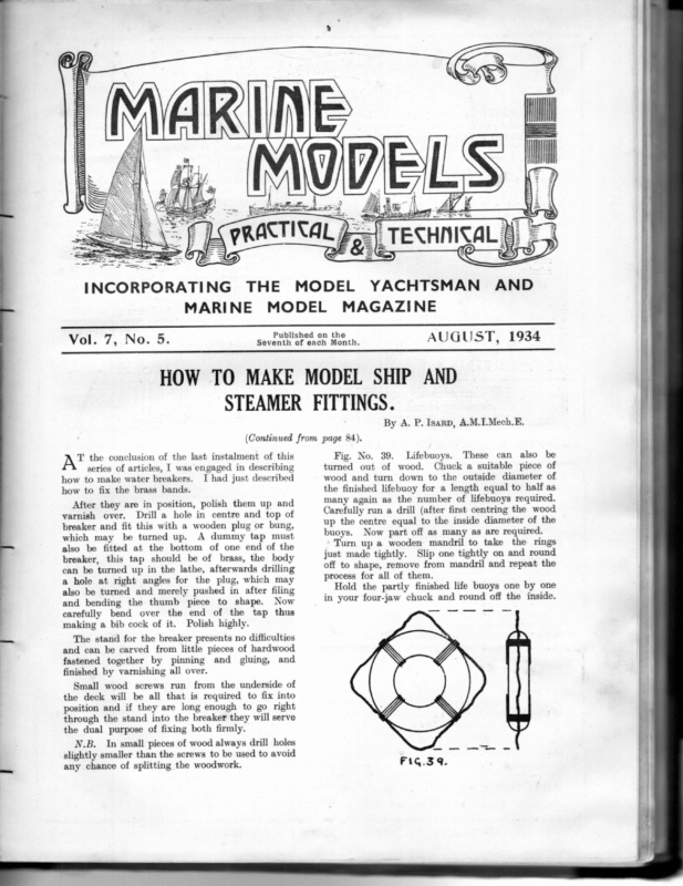
NDI wll} RW) SSS 7 i WY ZEEE: hf } S AA Auh es sa saeoman ss YY seseuseas eens es case SSSWWGUDSVTUUUNVDI0D 0000) DIT =. ES S > > = = N SS INCORPORATING THE MARINE Vol. 7, No. 5. MODEL MODEL YACHTSMAN AND MAGAZINE Published on the Seventh of each Month. AUGUST, 1934 HOW TO MAKE MODEL SHIP AND STEAMER FITTINGS. By A. P. Isarp, A.M.I.Mech.E. (Continued from page 84). } The stand for the breaker presents no difficulties and can be carved from little pieces of hardwood fastened together by pinning and gluing, and finished by varnishing all over. Small wood screws run from the underside of the deck will be all that is required to fix into position and if they are long enough to go right through the stand into the breaker they will serve the dual purpose of fixing both firmly. N.B. In small pieces of wood always drill holes slightly smaller than the screws to be used to avoid any chance of splitting the woodwork. ne a Hold the partly finished life buoys one by one in your four-jaw chuck and round off the inside. —_ process for all of them. le After they are in position, polish them up and varnish over. Drill a hole in centre and top of breaker and fit this with a wooden plug or bung, which may be turned up. A dummy tap must also be fitted at the bottom of one end of the breaker, this tap should be of brass, the body can be turned up in the lathe, afterwards drilling a hole at right angles for the plug, which may also be turned and merely pushed in after filing and bending the thumb piece to shape. Now carefully bend over the end of the tap thus making a bib cock of it. Polish highly. se how to fix the brass bands. Fig. No. 39. Lifebuoys. These can also be turned out of wood. Chuck a suitable piece of wood and turn down to the outside diameter of the finished lifebuoy for a length equal to half as many again as the number of lifebuoys required. Carefully run a drill (after first centring the wood up the centre equal to the inside diameter of the buoys. Now part off as many as are required. Turn up a wooden mandril to take the rings just made tightly. Slip one tightly on and round off to shape, remove from mandril and repeat the eer At the conclusion of the last instalment of this series of articles, I was engaged in describing how to make water breakers. I had just described
106 Remove from chuck, turn it round and replace in chuck, and repeat on the other side. They are now finished except for a piece of fishing line bound to them at four points as shown in sketch. Paint all over with the best white enamel and when dry, paint in black the name of your ship at the top of each and the date at the bottom. A ship’s bell is one of the fittings invariably associated with the ship herself, and is often an, elaborate presentation affair beautifully engraved with her name and sometimes with an inscription as a memento of some important event. It is regarded with pride by the ship’s company, and is kept highly polished for all to see and admire. We will now turn our attention to what is known as “running gear,” such as blocks, derrick blocks, gin blocks and pulleys, ete. These fittings are used on all kinds of boats, big and little, and for many different purposes and in many different forms and sizes. They may be of wood, brass, or galvanised iron, the material of which they are made suiting their different purposes; they may have single, double, or even three sheaves with shackle eyes and becket or without becket, hooks with and without beckets, hooks plain or swivel, etc.. etc., strops of brass, iron, or rope. A sheave is the grooved wheel or pulley over which the rope or wire runs, and may be of brass, galvanized iron, or lignum vite. A shackle eye is simply a fixed ring through which a shackle can be passed. A shackle consists of a U-piece with a small bolt through the ends of the arms. The one shown is the most usual pattern known as a “D” shackle. The “Harp” shackle has a bigger loop to the bow. FIG. 41. Fig. 40 illustrates a type in general use with a bulkhead bracket fitting. If it is desired to fix on a cabin top or similar place, the bracket will be of the double pedestal type. The bell itself may be turned from the solid as thinly as possible, leaving enough metal at the top for forming by filing its fixing lug. A hole should be drilled up through the inside into this lug to take the eyelet to which the clapper is to be attached, this little eyelet being either fixed by a touch of solder or screwed into place. Really the easiest way to make the clapper is also by turning, but this will be a somewhat delicate job. Leave enough length for forming a hook to hook it into the eyelet, afterwards closing up this hook carefully with a small pair of pliers. A small extension must be left below the clapper hammer itself to accommodate the bell lanyard. This lanyard is used to actuate the clapper and strike the bell, and it is usually a nice piece of fancy ropework. The bracket may easily be filed up from an odd piece of brass and a tiny bolt passed through the bell lug to fix same rigidly. Both bell and bracket must be very highly polished. If you are careful, and even if the bell is a very tiny one, it can be struck in the proper manner and will ring. A becket is a fixed eye usually at right-angles to the sheaves at the bottom of the block or pulley. A strop is the binding arrangement around the block which carries eye or hook, sometimes being a band of brass, galvanized iron, rope, or what is known as “ wrot-in.” This is a metal frame of wrought iron in one piece, in the centre of which the sheave revolves; the wooden cheeks or side pieces are screwed on to this frame. There is another rather uncommon, type of block called the ‘‘ Fiddle,’’ being merely two single blocks of different sizes in tandem made as one block. The method of manufacture is not difficult but Considering wooden blocks may be tedious. probably the quickest method is to first decide upon the overall size of the blocks required and the number of one size; take a piece of boxwood or holly and plane up a length to a rectangular section, this section being equal to the overall size of the blocks required. The length of this strip of rectangular wood should equal the length of the block, which will be about 50 per cent. longer than its extreme width multiplied by the number of blocks required plus a small amount to allow for waste when cutting off each piece. Now carefully draw a pencil line down the length of the strip, which must be exactly the centre line
107 of each sheave. Mark off with a small set square the number of blocks wanted, thus dividing the yet not too slack for the sheave to freely revolve on its pin. strip off into equal lengths. Find the exact centre Push the pin through one side of your block and of each division (this will untimately be the centre hole through which the “ pin ” or axle of the sheave is to be fitted); now with this as centre, adjust your compasses to the radius or just a little more than half the diameter over the size of the flanges of the sheaves, and describe arcs at the top and bottom of each division. Now use your small place the sheaves in position before finally pushing home; then cut off and make good. square at these points, and draw a line across your strip of wood at each of these places, and where they cut the centre lines of the sheaves already drawn will be the exact point at which a hole must be drilled right through. The diameter of this hole will be equal to the overall width of the sheave plus The block is now finished except for stropping, which will depend upon the use it is required for. Note carefully that all work must be done with the utmost care, as it is very easy to split a finished block before it is at last strengthened by stropping. Figs. 42, 43 and 44 illustrate a number of different: Fig. 42 shows a wooden block with three sheaves for rope stropping. Fig. 43 shows wooden blocks. another wooden block arranged with two sheaves stropped with wire and fitted with a hook. Fig. 44 a little for clearance. FIG.43. All this may sound rather complicated, but a glance at Fig. 45 will make the idea clear. Having drilled all these holes, drill out the inter- médiate wood as shown. Cut away with a very sharp knife or a small chisel, and smooth off the slots with a small ward or Swiss watchmaker’s file. Now drill your holes for the pins; this hole should be of such a size that it is a tight fit for the pins, which may be of brass wire. Now—and only now, and not before this stage is reached—you may, with your small plane, slightly round off the longitudinal edges. Saw off each little block. Each little block must now be shaped by carving, sandpaper, file and elbow grease to its finished shape, and all must be the same or as near as possible. If great care is exercised, manufacturing by this method will probably produce less split and damaged blocks than many others. SSANAY The sheaves can easily be turned up from brass rod and drilled all at the same time; the hole should be of such a size that it is a very easy fit, shows a single-sheaved wooden block stropped with wire and fitted with a hook and becket. Gin blocks Figs. 46 and 46a are all metal and used for handling goods in and out of cargo hatches and the like. Mark out on sheet brass the plan of your block, making the four legs longer than the outside diameter by the width of the sheave plus clearance (these are bent over at right-angles after the surplus metal has been cut away). Cut out another side frame from a piece of sheet brass, but this time rather larger than the finished size, turn up your sheave, push pivot pin through centre hole, and fix by touching with the soldering iron, and be careful to see that the pin is at truly right-angles; slip on the sheave, then place over the pin (which should be left fairly long) the other half-frame; the little bent-over legs should now just stand upon the legs of the other side frame, hold all together and touch each leg neatly with the soldering iron, cut off the projecting piece of your pivot pin, and give this also a touch with the soldering iron, file flush, and the job is finished.
108 Notice carefully that one of the legs is somewhat broader than the others and a small hook should be soldered in place as shown; to do this drill a hole in centre just smaller than hook shank, so that it file to shape and insert sheave. Slip in pin and either solder in place or lightly rivet. In the cases of either gin and derrick blocks, if is a tight fit. there are a number to make, make one piece first and use this as a pattern for the others before required for. Pulleys for gear leads are many and used for various purposes. Fig. 48 illustrates a single flat pulley for steering gears, etc. This is very simple The opposite leg to this is often extended with a hole drilled through to form an eye for a steadying line, but this depends what the derrick block is assembly. AEN a Re FIG. 46A, Gin blocks can be finished by painting with aluminium paint to represent galvanized iron work or blackened. Derrick blocks (Fig. 47) are used for very much the same purpose, but are somewhat easier to make. Carve from hard wood a section mould of the Bend round inside shape and size of the block. this a strip of brass of the correct width, pinch the two ends,together and solder up. Drill the eye-hole, The “ELLEN VAVASOUR.” Line of working model sailing ships. FIG. +7. FIG. 48. to make, and the construction can be followed from the sketch. It must be pointed out, however, that wellfinished blocks and pulleys add considerably to the appearance of any model. One important point that is often overlooked is to see that you work to a proportionate scale. Nothing looks worse than large and massive running gear in a small model, even if it be well made and finished. (To be continued). The latest addition to the White Rose Built by D. J. Boyle, Scarborough, 1934.
109 BUILDING A PLANKED MODEL YACHT. (Continued from page 98). Rae hull of the yacht is now ready to receive the deck beams and deck. The next step is to prepare the proper deckbeams. These should be of pine or light mahogany, }’ thick and about ?” deep, cut to length according to the position they occupy. The bottom is always straight and the top cut to camber as given on the plans. They are all squared round. (No! I am not an Irishman, and the meaning of this sentence is perfectly plain.) The positions of the deck-beams measured from bows are as follows: No. 1, 8”; No. 2, 15”; No. 3, 203”; No. 4, 28”; No. 5, 32)’ ; No. 6, 35”; No. 7, 403”; No. 8, 463”; No. 9, 503”; No. 10, 653”. From No. 2 to No. 3, a strip 2” wide by }” thick should be “ housed” in dead centre to take the jib rack. From No. 4 to No. 5 two parallel strips are fixed 2” on each side of the dead centre. These strips are 2” x }” and form reinforcements for the mast slide. From No. 6 to No. 7 two strips are housed in the beams. These are 1}” either side of the centre-line and should be 3” x $#”, and serve to reinforce the hatch. It is assumed that an oblong hatch will be fitted. From No. 9 to No. 10 a strip ?” x }” is housed and forms the reinforcement piece for the slides of the steering gear and rudder post. All these strips should be glued and screwed with }” x 0 brass screws. The deck-beams themselves are housed in the inwales (i.e., let into), glued, and screwed with 2” x 0 screws. It should be unnecessary to add that the ends of the deck-beams fall inside the sheer plank. Beating sheet can be fixed to beams Nos. 9 and 10. Steering pulleys can be on beam Nos. 7 or 8. Before all the deck-beams are fixed, the mast step and rudder tube have to be put into position. The mast step is about 33” long and is made from ¢ square brass tube. Slots are filed in this to take 7s wire. Before this is fixed into position a mast ferrule must be made to fit it. It is screwed on to the backbone in the position set out with two 3” x 2 brass screws. The rudder tube is of #3,” brass tube. During the fitting of this, the centre-line stretched from bow to stern should be in position. In fact, this will not be in the way whilst fitting most of the beams, and the measurements on each side of it carefully checked to see that they are the same. At the point where the rudder tube emerges from the top of the backbone a small brass plate is soldered after fixing. This plate is really not necessary, as the screwing to the skeg and fixing through the strip at the top should be sufficient. If no plate is fitted a little stopping should be put round the tube. After the deck-beams have all been fitted, the whole inside should receive a further coat of varnish, also the tops of the beams and the wales of the hull. When this is dry, the hull is ready to receive the deck. Always keep varnish brushes in raw linseed oil, and before using see that all oil is cleaned from brush with turps. The material for the deck should be a board of pine 6’ 6” long by 11” wide and }” thick. isin the rough, post passes up inside this and is also of brass tube. It is, therefore, advisable to buy the two tubes at the same time and thus ensure a suitable fit. The rudder post must not bind or stick in the tube, and must, therefore, be an easy fit. The rudder tube must be cut to length. It extends from the bottom of the skeg to a point 4” above the deck. From the bottom of the skeg to where it enters the backbone two-thirds of the tube have to be cut away, leaving a strip which is bored and countersunk for the 2” x.0 brass screws which hold it to the sternpost. The greatest care must be taken not to bend the rudder tube. It must be fitted perfectly upright and should pass through the strip between deck-beams Nos. 9 and 10. If this smooth over with a small plane, finishing with three grades of glass-paper. To do this place the wood on a flat bench or table. Hold one end with a small ‘G’ cramp, then shoot one edge dead straight and put a centre line down the full length of the board on each side. Measure the distance from the stern to the rudder tube and bore a }” hole dead on centre line. Place the deck in position temporarily with the hole over the tube. Make sure that the centreline on the underside of the deck coincides with the centreline of the bows and stern. Screw each end with a single }” x 0 screw to keep the deck from moving. Turn the hull upside down over the deck and mark out the deck }” larger all round than the hull. Remove the deck and cut to shape using a Starting amidships work forward the bows and then aft to the stern. This sharp penknife. to The rudder By “549.” prevents the wood from splitting. Make certain that the deck is perfectly flat whilst it is being cut out. Replace on boat putting in the screws at bow Put in about six more screws on and stern first. each side, and then clean off the surplus wood all round. Take out the screws along the sides but leave those at bow and stern. Then mark along each side the positions of the deckbeams putting the marks on the top of the deckedge where they will later be covered up by the covering board. Then remove the last screws and take the deck off. Give three coats of goldsize each side and lay aside. Next try the lead keel on the wood and cut and fit the carrying handle. When this all fits perfectly, remove the lead from the wooden keel.
110 Give the wood keel one coat of goldsize along the edge where it joins the lead. Put some soft stopping along the lead itself to form a bed. Replace the lead and tighten up with temporary nuts on the bolts, and leave to set hard. The brass shoe is now fitted. This is made of brass strip 2” wide by #” thick. The fore end starts 14” above the fore-foot and continues round finishing about 1”above the lead on the after part of the keel. The overhanging ends of the shoe are fixed to the hull by means of 3” x 1 brass screws. Bore and countersink holes for about four of these screws on the forefoot and three on the afterpart of the keel. Where the shoe crosses the bottom of the lead four }” x 4 screws will be used. Shape the shoe to the keel, bore and countersink the holes for the screws. Then lay in position and mark on the lead the positions of the screws. Holes will have to be bored at these points to take the wood plugs into which the screws are inserted. After marking remove the shoe and bore about }” deep with a drill a little larger than the holes in the shoe. The plugs should be mahogany and after they have been tapped home must be cleaned off flush with the bottom of the lead. Then put a bradawl mark lightly in the centre of each plug for a start for the screw. When all is ready start to fix from the stern finishing up on the forefoot. When screwing into the lead put a little soap on the screws which will prevent them snapping. The next step is to clean off the projecting brass up the sides of the forefoot and stern. On the forefoot the screws can be soldered over. During these processes be care- ful not to break off the overhangs that are going to be fixed onto the hull. Before fixing the keel to the hull, let in a small brass dowell forward and aft. Bore holes to receive these in the underside of the centre member of the backbone. This will prevent the keel from of japan goldsize on its upper side. Obtain some short pieces of 3” x 1” batten and cut roughly to the shape of the deck. Screw these down on the board keeping inside the outline of the deck about }” all round. Then screw the deck down on top of the battens using about a dozen }” x 0 screws put through the holes already bored in the deck. Go lightly over the deck with F.O. glass-paper, and dust off with a cloth. With a pencil, space out the width of the lines representing the planking. In the case of this boat I made it }’. Starting from the outside the first planking line should be 3” in to allow for the covering board, and after that 1”. These planks are marked out on either side of the pencil centre line which was put in earlier in the proceedings. : Get a piece of soap and rub round the edge of the deck, also put a little on the brass shoulders of the gauge. During the marking out this should be occasionally touched with a little water which serves to lubricate it. Set the gauge to the first line which is }” from the edge of the deck, and before filling the pen with ink, round to see that all is in order. try the gauge Fill the pen with the waterproof drawing ink using the quill that is supplied for the purpose. See that no ink gets on the outside of the leaves which form the pen. After testing the pen to be sure it is running well, mark out the first plank. In marking out the deck hold the gauge at a slight angle and move away from you keeping the shoulders of the gauge firmly pressed against the outside of the deck. Stop all the lines }” out from the pencil centre line. When one side has been marked out, turn the board round and refill the pen and do the corresponding }” line on the other side. Next set the gauge to the second line and put that in on both sides of the ship. Do not forget to stop all lines }” from the centre- twisting when fixing on. line. Screw onto the shoulder of the gauge two pieces Of course the lines in the stern do not go near the centreline as far as the first four are concerned at all events. There is a taffrail across the stern (or will be when the boat has finished) and to accommodate this a semi-circle is drawn across the stern about 14” forward of the extreme end of By this time the deck will be dry and ready for lining out to represent the planking. There are several ways of doing this but the ordinary novice will find the following the easiest method. Take your cutting gauge and remove the cutter. of brass tube about 14” long, one on each side of the stem of the tool. These brass pieces should project about 34” below the bottom of the shoulder. The actual lining is done with a draughtsman’s drawing pen and waterproof drawing ink. Take the pen, seeing that it is perfectly clean and insert in the slot in place of the cutter. Tack a panel pin each side and bind the pen firmly in position so that it cannot wobble about. Take your ‘SX’ board or deal and lay the deck on top of it. Pencil a line round the deck and remove it. The deck can now be given two coats the boat. This semicircle extends from one 3” line to the other and the next four planks run up to this semi-circle. When all the deck lines have been put in, the next step is to mark out the king plank. The method on which a full-sized yacht has her deck planked is that there is a plank round the deck edge known as the covering board. This is indicated by the }” line we have put in. The remainder of the deck is laid in narrow planks laid parallel to the deck edge as indicated by the }” lines we have marked in. Down the centre of
111 Take a ruler and draw a centre line extending }” line square with the on either side of it at each of the points where the deck lines representing the planks are }” away from the centreline. When these are all put in, start again amidships and working forward draw lines from the outside of the first squared line to the centre of the second squared line, repeating until the bows are reached. Start again amidships and do the same thing This gives the shape of the king plank, which working aft. Turn the board round and duplicate these lines on the other side of the centreline. must now be coloured to represent teak. brown is Vandyke about the nearest colour to teak. colour should be used for this job mixed goldsize,’and applied with a sable pencil Artist’s with brush. When this is thoroughly dry, the slot for the mast and hatch opening can be cut out. This must be done on a flat bench after removing the deck from the battens. First bore a 8” hole at each end of the mast slot using a centre bit and working from the outside. The wood between is cut out with a sharp penknife top of the deck. The working from the hatch can be cut out similar fashion or direct with a penknife straightedge but in the latter case great should be taken not to split the wood. in and care The hatch cover can now be cut to size from a suitable piece of pine. After giving three coats of goldsize, glue and pin the cork on the under side about }” inside the edge all round. The top has then to be lined out with the drawing pen and either the gauge or a straightedge can be used. If the gauge is used the hatch cover can be held in the left hand during the operation. Draw a line }” from the edge all round and then two lines }” on either side of the fore-and-aft centre line. These lines represent the stiles and rails of the ‘light’ of a skylight; and we have now to put in lines to represent the bars that protect the glass in the light. Divide the length into three spaces and The Next comes the fixing of the deck, but before doing this give the inside of the hull a final coat of varnish, also the top of the deckbeams and the upper edge of the hull. Mix some stopping to a paste and put a little all round the upper edge of the hull. Put the deck on by first putting the hole over the rudder tube, then screw in the screw at the bow and with the one at the stern. Put in the remainder of the screws working first from midships wall attention. round the hatchway now requires This should be of mahogany or cedar §” wide by }” thick. It is mitred at the corners and fitted inside the hatchway. Copper rivets should be used to fix this to the deckbeams at the forward and after ends and the reinforcements at each side. The wall should project at least above the deck to form the hatch coamings. 4 The covering board and taffrail can now be made and fitted. For the covering board two pieces of cedar or mahogany are required 6’ 3” long by 1” wide and 3” thick. These lie flat along the deck and the upper corners should be slightly rounded off with glass paper. They are given a coat of goldsize or varnish on the underside and edge fixed to the deck with copper pins. The taffrail is of wood to match the covering board and 3” thick. It is cut to the shape of the stern and 3” less than the markings on the deck. It is fixed with }” x 0 brass screws. The keel can now be permanently fixed to the boat. Remove the 3” x 2” batten from the bottom of the hull. The screw can be got at through the hatchway to do this. Having made a stand beforehand, place the keel complete in on a table or bench and place the hull the stand on to the keel. Do not attempt to put the keel on to the hull in an upside down position or you may subsequently find that you have broken a deckbeam. It may now be found that the 14” overhang of the brass shoe may need to be let in flush at the forefoot of the centre member of the backbone, also the brass itself may need filing down a bit. This means taking the hull off again. (T’o be continued). ;” on each side of each division draw lines to represent the bars. When dry fill in with Vandyke brown leaving the lights white. When all is dry give a coat of Rylard Varnish. follow every 3” and spacing in between the rib stations. The screws into the deckbeams should sink just. below flush and be filled in with ‘clear’ stopping. This will prevent the water getting at the screws and discolouring the pine deck. A SLIGHT CORRECTION. | rae’ month we stated that the 10-rater “Cunior’”’ winner of the McDonald trophy, was from the lines of “Evadne.” Her owner now informs us that the sections throughout the boat were proportionately increased to give her a somewhat larger displacement, and that the keel was bulbed in order to get the lead lower. He informs us that the boat is very pleasant to handle and a great success in every way. The bent mast rig has proved particularly good to windward. is We should, therefore, have stated that “Cunior’’ an “Evadne” with the displacement increased by about 10 per cent. + streadtidatitisitie. ee are let into this. to the bows and then from midships aft. Finish by screwing to the deckbeams. To screw the deck down use }” x 0 brass screws, putting one about mete.1 the deck a straight plank is laid known as the king plank, and the ends of the other deck planks
+, ot 112 (Continued from page 102). Bee passing to a number of other matters, I will conclude from last month my remarks about flash steam boilers for racing craft. Nowa boiler of this kind generates a tremendous volume of superheated steam at a very high pressure. In order to give this room to maintain a steady flow, it is advisable to increase the diameter of the tube towards the delivery end. If the delivery end is too small back pressure must result, with the result that the engine will not receive the full volume. Two diameters will be sufficient, and the first part might be }” and the other #”. The exact Jengths of each will depend on the arrangement. The joint between the pipes requires to be well made. If the small tube can be threaded to screw inside the larger, this is the best way, brazing it up afterwards with hard spelter. An alternative would be to weld the joint, but this would have to be properly done. Failing these methods a little gocket can be made consisting of a short length of pipe screwed one end to suit the }” and the other the -3”. In any case, the joint must be arranged to fall in a position where it is not directly exposed to the flame. For this racing boiler a very light casing of tin plate will be suitable. This also must be lined and thin sheet asbestos used. The funnel at the after end will be very large. The great length of the coils will necessitate their being supported in several places to obviate sag. For this purpose wire that will stand heat should be used. No particular lay-out of boiler or shape of casing is specified, as every builder has his own ideas on this subject. x ee KOK K In the course of my last article I mentioned a little union for the main steam pipe, but this union has a number of different uses, not only for steam but also for petrol. This union is shown in Figure A and is almost self-explanatory. The two pipes have an overlap by reason of one fitting inside the other. The male pipe is formed of a short end brazed on to the end of the boiler tube or whatever it is desired to connect up. The female pipe is usually part of the steam chest or some component part of the engine, but this union can be used to connect two lengths of pipe if required. The male pipe has a collar brazed on to it. If this is a steam pipe this collar must be steel, but phosphor bronze would be suitable except when subjected to extreme heats. Copper or brass could be used in place of phosphor bronze, but are too soft to wear well. These metals have the advantage of not rusting. Figure A. The collar has to be turned up after it has been brazed on, and this explains why this male pipe is formed of a short end of tube brazed on to the end of the boiler tube. The two ends of the pipes are arranged to be a good fit. The actual union nut is hexagon. One tip that may save the novice trouble is that if he is using copper pipe for the male part, this metal is soft and liable to collapse when being turned up, or even by the pressure of the jaws of the chuck. To obviate this a piece of steel or hard brass rod—or, in fact, anything suitable—can be inserted into the pipe during turning. The proportions of this fitting will largely depend on the purpose for which it is being used. If it is a high pressure steam pipe, then naturally, the whole thing must be more sturdy than a joint in an oil pipeline. If the pressure is small, the whole fitting can be made extremely light. In the case of very small pipes (say } in. or under) the spigot is really unnecessary, though it makes it a quick and easy job to connect up after unscrewing the union for any purpose.
113 It should be mentioned in passing that the drawing illustrating this fitting is not to scale and is merely to show the principle of the thing. A useful little check valve is shown in Figure B, which can be used for any purpose where a nonreturn valve is required. This is a simple fitting as otherwise the seating of the ball may be damaged. made out of standard stock material. to avoid damage, The body can be made of brass or phosphor bronze, and can be either round or hexagon. The two pipes are copper silver soldered into the body. The bottom (or inlet) end is parted off in the lathe, leaving a little extra length for cleaning up, and drilled up to form the recess for the end of the inlet pipe. Before taking out of the chuck also bore out the recess for the outlet pipe. Remove from the straight run no risk of melting the brass. The easiest thing is to make both inlet and outlet pipes from short Take a short length of copper tube and a light. hammer. Using the tube as a punch, give the ball a sharp tap to seat it finally. the force is evenly distributed Before tapping the ball down on the seat, care must be taken that not only the inside of the body but also the ball itself are scrupulously clean. This can be ensured by washing out with a drop of clean petrol. One point which is worth mention is that the ends of the two tubes should fit tightly into their recesses before soldering. This ensures solder not. leaking past and choking the inside of the pipes. This applies particularly when a long length of pipe is used. The best way to ensure this is to bell the end of the pipe slightly. i that round the seating. oe a so Copper tube is used and the punch must be dead Having cleaned up the job, it is put back into the chuck the other way round. The outlet can be arranged between two of the jaws of the chock. Face off the top end, centre and drill right down through the valve as far as the inlet pipe, and clear the passage. The next step is to open out the body of.the valve to make the ball chamber. There must be a good clearance round the ball itself to ensure easy working. If the ball chamber is made oneand-a-half times the diameter of the bore of the pipes, this should be perfectly satisfactory. The ball chamber must be bored out to provide a square shoulder at the bottom. This ensures a good seating for the ball. The hole for the outlet must now be drilled. If a long length of pipe is being used, this would have to be done before the outlet pipe was soldered in, but it is more satisfactory to use a short length and drill this hole at this stage of the proceedings. There are several little things that are worth mentioning. If a long length of pipe is being used, it can be coiled up out of the way round the body of the chuck in a trailing direction. If it is coiled the wrong way, it will open out when the chuck revolves. It will be seen that the top of the valve is closed with a screwed plug. The size hole should, therefore, be selected to suit the worker’s tool-kit. The thread for the plug must not be carried too far down, ELTET TTT i ised ial lengths of tube rather than use the ends of long pipes, but this depends largely on circumstances. In order ee chuck and silver solder the two pipes in position. Easy running silver solder should be used so as to The work is now taken out of the lathe. to ensure the ball seating properly, insert the ball. Fisure C. The plug that closes the top end of the valve is shown in the drawing with a cheese head, but it can be hexagon. The plug itself can be used to give an adjustable restricted lift to the ball if required. A common type of screw-down valve is shown in Figure C, and this can be made in very similar fashion, but there are a few differences that should be noted. The hole in the body for the stem is drilled out to tapping size, and a clearing drill passed down for the length of the plain part on the stem. This should be a nice fit, but must not bind. The hole is then tapped below this part down to the outlet pipe. The seating is just below the outlet pipe, but this distance is somewhat exaggerated in the drawing for the sake of clear reproduction. It will be noticed that the bottom of the seating is not square, so all that need by done is to drill out and tap the hole. A plug tap must be used to finish with. The top of the hole is chamfered off to make a little chamber to accommodate the packing under the nut.
114 The stem of the tap can be of german silver, or, if the maker does not mind a hard task, rustless steel is admirable for the purpose. The stem is cut rather too long at first, so that the end can be put in the chuck. The top of the stem can have a T-piece or, better still, a wheel. The latter is far better to operate, and in the assumption that the worker will go to the little extra trouble, this is described. A piece of brass is parted of a rod to make the wheel. This is centred and drilled to fit the stem. It is then silver soldered to the stem and the borax cleaned off. In Figure D this screw-down adapted to a blowlamp burner. valve is shown The whole of the body is not illustrated, but this should be long in order to dissipate the heat. The packing used in this should be graphited asbestos, as otherwise it will char away in no time. The lower end of the body should be heavy metal, but this should be reduced towards the upper end. The extra thickness at the lower end is advisable, as it may be necessary to shut down under difficult conditions, when accidental rough handling may occur. BURNER FEED PIPE § The stem is mounted in the chuck by the spare end. The lower end of the stem is now shaped. This end is not reduced to the extent shown, but here again it was necessary to exaggerate matters for the purpose of clear reproduction. The stem is now threaded, a fine thread being used. The thread must start immediately above the reduced lower end, but must not be carried too high. The part of the stem that will make contact with the packing in ordinary use must be parallel, round and highly polished. The wheel can now be finished off. It is first turned up true and the periphery knurled. The knurling should be sharp to ensure a good hold when the fingers are oily. The wheel is lightened by being turned out to the section shown, and this can be carried further by drilling if required. The packing nut must be a good fit without binding. In the case of water a strand of cotton string, soaked in warm tallow and graphite, makes a good packing, but there are also a number of other packings that can be used. Figure D. The back plate of the burner screws on to the body, and the inside boss is also threaded and acts as a lock-nut. It will be noticed that there is a chamber inside the boss below the end of the body. This accommodates the gauze filter and the little spring ring that serves to hold it in place. These details were all described recently when I was writing on the subject of blowlamps. — One little point that may be referred to is that the nipple has an angle seating, and the inside boss must be bored to match. (To be continued.) lamen-cu Shae.“=“By GN. Munvo. apie AR: ae tin ;a (Continued from page 82). T HE rope work must have our attention next, and we will consider the standing rigging first of all. Most modellers want to be very correct and have each rope or piece of rigging the exact size, and the factors and sizes I am about to give are those which ‘were commonly used on ships of 100 to 150 years ago. I would suggest that the modeller first obtains a supply, or makes sure the supply can be had when the stuff is wanted, of as many different sizes of cord as possible up to the largest used on the ship which was that used for the fore and main stays. A ship of the size of our Indiaman would have stays of about 14-in. circumference. The actual size is not so important as it appears to the naked eye. A hard smooth cord-like surgical silk or good mackerel line looks finer than a soft furry cotton, and though they may all pass through the same gauge the soft cotton will give the model an over-rigged appearance if any attempt is made at completeness. A dull flat yellow surface always looks bigger than a smooth shiny black, which fact is well known to artists and fashion designers, and
rigging is set up or by using black material to start with. Personally, I find that a liquid black applied afterwards tightens up the rigging and also that the binder in the colour acts as a fixative to all knots, servings, etc. On the other hand, black applied afterwards very often sets a material quicker than if it is put in the material during manufacture. A good black dye does less harm than paint and varnish. I have some samples here of rigging done some twenty years ago, and where varnish was used it is quite rotten and has been for several years. Moreover, when the modeller wishes to use a fixative for serving, etc., the gum will hold much better between two white surfaces with the black applied afterwards when quite dry than if the two parts are blackened and then glued or gummed. On large scale models brunswick black is the nearest approach to tar in its application and colour that I know of, but the durability is open to doubt for the above reasons. On very small scale models, where the detail is too fine to include ratlines, etc., black silk or cotton is perhaps the best to use as colour applied after- wards is liable to clog and make the rigging look stiff and clumsy. Wood is not very satisfactory for small fittings, and some substitute must be found to take its place. For many years I have been saving old tooth-brushes made of bone and other white substances, and these are always coming in handy for small carvings such as blocks, figure-heads, mast caps, etc. Moreover, the natural white solves the colour problem, and when other colours are wanted a dye soon gives the * desired tint better than any wood. Now to start on the actual rigging and fitting out. The bowsprit must be stepped into position between the knight heads. It is secured by the gammoning in two places as will be seen on the rigging plan (June issue). top and Gammoning cleats are nailed on the sides of the bowsprit gammoning slipping down. to prevent the The position of these is found by placing the top edges directly above the after-end of the long holes cut in the beak just forward of the hawse holes. These are called the gammoning holes. The rope used for the gammoning is passed through the hole and over the bowsprit, back through the hole, and so on, unti! eight to ten turns have been taken. The turns are taken from the after-part of the bowsprit, working forwards to the fore-end of the gammoning hole working aft. When the turns are complete the whole is seized in the middle with a throat seizing. The same procedure applies to the second gammoning. The size of the rope depends on the number of turns taken or perhaps I should have put it the other way round, or -4 the diameter of the bowsprit. A throat seizing is put on at the lower end of the bobstay in front of the cut-water. The size of the rope used should be about 9 in. for our ship, or the diameter of the bowsprit x -3. _—— As most of the standing rigging is black, we must decide whether the black is to be put on after the but on the model it is easier to gauge it from the Jength of the gammoning hole which is 18 in. which in its turn will take nine turns of 2-in. diameter rope, usually called a 6-in. rope. If a bigger rope is used the turns will be proportionally less. There are two bobstays set up from the two holes in the cut-water, just under the figurehead. These bobstays take the form of a loop, the ends of the rope being spliced into each other and the whole served over. The splice comes on top of the dead-eye, which is seized in with a round seizing. The deadeye should be in diameter about 12 in. On the bowsprit a collar is set up to take the lanyards of the bobstay deadeye. This collar has either a deadeye, or open heart, turned in under the bowsprit. The usual method is to take a length of rope and splice a thimble in each end, then a short distance from one end seize in the deadeye. A lanyard is made fast to one of the thimbles and, after the collar is passed round the bowsprit, threaded through the other thimble and back through the first and so on until it is strong enough. It will be noticed that by seizing the deadeye nearer the one end the two thimbles come on the side of the bowsprit. The size of the collar will naturally be the same as for the bobstay. In the same way the collar for the bowsprit shrouds is set up, but here it is necessary to provide two deadeyes in the collar—one for each side. The thimbles will come on the top of the bowsprit in this case. The size of the bowsprit shrouds will be the same as for the bobstay and in the same way take the form of a long loop. The after-end has a thimble turned in and set up to an eye-bolt placed just aft of the lower edge of the trail board. Care must be taken that the shrouds do not foul the cable when the ship is at anchor, and the best position will be seen from the shape of the bow. Stops or cleats must be nailed on the bowsprit to prevent the above-mentioned collars slipping down. We must next go on to lower masts and get the shrouds over them and set up. It will have been noticed that the fore and mainmast have an odd number of shrouds. The odd shrouds are known as swifters and are usually the foremost ones. There are two methods of setting up the swifters : the one is to put on a mouse just where the throat seizing would come, pass the end of the swifter round ‘the mast-head and eye-splice it round the standing part below the mouse. The other, and more usual in the Merchant Service, is to use the end of the swifter as a runner pendant, and it is this latter method which I propose to adopt for our Indiaman. The foremost shrouds or swifters are served all the way, including the runner pendant. SS at eal Lal though T am not prepared to discuss the qualities of silk stockings they may be taken as the very best guide to what I mean.
116 ‘The starboard ones are put over first. The pendant is really a short length of shroud which, if continued, would have a deadeye turned in and set up like the others. As a pendant it has a thimble turned in and hangs down the side of the mast ready for the runner tackle to be hooked in. Apart from the swifters there are four pairs of shrouds on the foremast and five pairs on the mainmast. The size of shrouds should be about 9} in. for our ship, or the diameter of the mast x -306. The deadeyes are usually just a little less than half the diameter of the mast. Ours will be 12 in. for both the foreand the mainmasts. The shrouds are turned in left-handed if cable laid and right-handed if hawser laid. Cable laid is the most usual on big ships, and in this case the ends will lie aft on the port side and forward on the starboard side. It must be remembered that in turning in the deadeye the shroud is crossed about itself and seized with a throat seizing close to the deadeye. The end is seized in two places above and the point stopped with canvas. On a model the stopping is not necessary and would not be seen. Lanyards are always half the size of the shrouds and the correct ratio must be remembered. A 93-in. shroud is about 3 in. in diameter and the 4}-in. lanyard is 1} in. in diameter. It has been mentioned many times the routine of putting the shrouds over the masthead—first starboard and then port alternately, working aft—so I will not repeat that here. I should mention here, however, that when runner pendants are separate they go on first and then the shrouds, and finally the swifters, but, as mentioned above, we have combined the pendants and swifters in one. On the mizzenmast we have an even number of shrouds, and so the burton-pendants must be put on separately. They are made from two lengths of rope joined together with a cut splice, and the outer ends have thimbles turned in. The cut splice must be big enough to pass over the masthead comfortably. The ends hang a short way down each side of the mast ready for the tackles to be hooked on. The mizzen shrouds are, of course, smaller than those on the fore and main. On our ship they will be about 6} in. or -306 the diameter of the mast. The deadeyes should be 8 or 9 in. in diameter. All the shrouds on the three masts are set up taut, but not too taut, and then catharpined in. This is done by lashing a piece of wood across the shrouds like a modern ratline. This strip of wood is called the futtock stave, and its position is the length of the head below the top and on the inboard side of the shrouds. If the first pair of shrouds come in the way of the mast a little copper sheathing is nailed round the mast and the catharping leads from the foremost shroud round the mast and back to the second shroud. The rest cross to their opposite numbers and another pair cross diagonally from the foremost on the one side to the aftermost on the other. When these have been set up taut the futtock shrouds are hooked into the deadeyes of the topmast rigging and the lower ends with thimbles in are lashed to the futtock staves. I should mention that the shrouds are served round the masthead and down to just below the futtock stave. The futtock shrouds are likewise served throughout their length, and those on the fore and main are made of the same stuff as the mizzen shrouds or, say, 64-in. rope. If a futtock stave is not used the alternative method of securing the lower end of the futtock shrouds is to take a half hitch round the lower shroud and seize the end in two places to the lower shroud, to which it is attached. The stays are next got over and there are various methods of setting these up. It is usual to double the fore and mainstays by the use of preventer or springstays. A cleat must be nailed to the after side of the masthead, so that this end of the stay falls clear of the sharp edges of the cross trees, etc. The forestay passes up through the lubber’s hole, round the mast, and down to the bight of the stay. A mouse is worked into the stay just below the forepart of the top and the end eye-spliced round the bight of the stay. The whole of this upper end of the stay is served down to just below the mouse. On the model it is hardly worth while unlaying a long length of the stay to make the mouse in the form of a Mathew Walker or Stopper knot, and then relaying it again,as the whole is covered by the serving. Quite a good mouse can be made by glueing a strand of cord to the stay and winding round until the mouse is formed. It will look very neat when the serving is put on over this. At the lower and forward end a heart is turned in and the stay set up by means of a lanyard between the heart and a collar-heart on the bowsprit. The size of the forestay is generally 50 per cent. bigger than the shrouds, and in our case will be 14}-in. cable-laid rope. The preventer stay is put on in exactly the same way and goes above the forestay. It will be noticed that there are a number of collars on the bowsprit at this point. The order from aft should be : first bobstay, forestay, bowsprit shrouds, preventer stay, and second bobstay. Beyond this again the collar for the sprit sail-yard is lashed on. The mainstay and springstay have their upper ends fashioned and set up like those on the foremast, but the lower ends will be somewhat different. There are several ways of anchoring the mainstay, but perhaps the neatest is to turn in a collar just abaft the foremast and have collar-heart turned in to a long loop encompassing the foremast and passing through holes in the knight heads and over the bed of the bowsprit. It then acts as an additional security to the bowsprit. The splice will come at the after-end of the collar. If the mainstay is set up similarly to the forestay, by an eye-bolt on the forecastle, the stay passes the foremast on the starboard side, where there is
117 a jumper provided to prevent it rubbing the foremast. A cleat will also prevent it rising. The springstay is not quite so elaborate, and one method is to pass it round the foremast and eyesplice it about itself. A pair of cleats will have to be nailed to the foremast to keep the springstay down. Sometimes the spring stay is set up like the mizzenstay, which we will consider next. springstay is below the mainstay. The The mizzenstay is moused and served like the others, but the lower end generally passes through a bull’s eye set up on the mainmast and so leads down to deck, where it is set up with a pair of deadeyes or hearts. The bull’s eye has a strap or collar similar to those on the bowsprit and is formed by a length of rope with thimbles in the ends, and the two lashed together with a whipping. All the above collars, etc., are wormed, parcelled, and served. On the model it is only necessary to serve them with very fine thread or silk, to give it a smooth even surface. Next month I shall include a page of diagrams which should make the above quite clear as to shape, size and general appearance of these smaller fittings of a ship. (T’o be continued). The displacement figured on is Hb. under the limit to give builders a little leeway, but if desired the boat could have a little inside bring her to the limit of 12lbs. ballast added to The boat would be powerful and stand hard driving, but nevertheless a hollow mast would be an advantage. Smaller suits should have smaller largest suit of sails is for very light weather only, and should be of very light material cut with a slight amount of flow. She would be spars. The decidedly tender with this rig. The normal working suit should be cut flat and she should carry this in anything up to a strong whole sail breeze, The storm suit should be dead flat and she should carry this in practically any weather. Most builders unless racing on inland sheltered ponds during the summer will be advised to get the two smaller suits only. The deck lay-out is shown.—The gunwale eye is for the beating gye—One point to be observed is that owing to low freeboard, and the fact that reserve buoyancy is detiberately reduced in the top-sides, the boat would be wet and a well fitting hatch is essential, also a little tube above deck on the mast slide. “Eudora” is very similar to “Iris,” our 50—800 class design. At first sight the two classes would appear to present different problems Marble-head but actually they are very similar. In the 36” displacement is limited, in the 50—800 sail area is limited and L.O.A. is limited in both. If displacement is limited, as well as beam and depth, this automatically limits sail-carrying power. If sail is limited, it automatically restricts beam and displacement. So in reallity the two classes are very similar. It might be thought that a canoe stern is unwise in either class. If displacement was unlimited in the 36”, or sail area in the 50—800, the logical boat would be one with transom stern and snubbed forward waterlines. In any case with limited L.0O.A., the L.W.L. will be as nearly as possible the full length of the boat. Again, it might be considered advisable to take the full beam of 9” and depth of 11”, but with a limited displacement, the object is to distribute this advantageously over the given L.W.L. length. The lines are reproduced one-third of full-size but we advise anyone intending to build to obtain the blue prints. The saving in trouble is worth the outlay and fear of inaccuracy is obviated. Mhtott ie ene A is for a 36-inch Restricted Class Limits for the class are :—L.O.A. 36”, beam 9”, depth of Hull 11’, displacement 12Ibs. model + design AN APOLOGY. 5 Sa sad death of Mr. E. E. Marshall has thrown much additional work on our shoulders. Coupled with this the illness of the Editor’s wife has caused us a great deal of anxiety. She is now out of danger and on the road to recovery, and we are making strenuous efforts to overtake our correspondence. If any reader has written us and not received prompt attention, we ask their kind indulgence. OUR DESIGNING COMPETITION. = regret that we are not yet in a position to announce Mr. Chas. E. Nicholson’s decision as to the winner of our competition but hope to be able to do so and publish the winning design in our Special September number. aon OUR DESIGN. ‘Cy This is a new design which has not yet been built, but we think she will prove fast and reliable. Full size lines with sailplan are available from these offices, price 10s. 6d. post free. tee: Waterlines are spaced }” for bread-and-butter building but she would also plank quite easily as the lines are not forced anywhere.
fe) \ wn WLI3 a | 4 VA a WL3 oe WL6 LEADLINE _——— j U cea Se WLS F oe WL4 ed N WL7 WL 4 . SC / w va ee — wts ee —— mS 7 WL 6 \ a | N OF® eS SS 7 WLIO WN KN = 4 o—geg MBs: y wis \ APPROX. POSIT} 3 Bees ° \ _s 2 pee oe LWe \ \ WLI3 dk. a: Dimensions. L.W.L. 34-0″, DEPTH (Max.) 10-35″ L.0.A, 36-0 183, 7-95 Beam (Max) DRAUGHT Dispracement (Fresu water) 11 & Ibs! Note, Displacement can be increas- ed +5 full 12 Ibs permitled with advantage, but amateur builders ave advised to allow a margin and complete with a | few ounces of inside ballast. i WL 3 \
119 al 10 AUfT7 (WTO EN YZ ot S6-INS NS \\ QIN “is Lbs. Oz. Hurt 2 LEAD DECK PAINT Ria SUNDRIES 7 £ ¥ WL WLS 10 RESTRICTED CLASS. Marine Mopets, 8 8 8 GoLDEN House, Gr. Purreney Street, LONDon, W.I. 12 4 iW DECK 7 4 i) EUDORA _ de. > ZX : ; 12 : ep! LWL .Hy = eee
120 Eypora. Li ght Weather Suit. 36” REsrricrep CLass. ein eit = 986 Jib Main 205 572+ 77? Main 449= 614 Working Suif. Storm Suit. Jib 165 —— Big Spinnaker (Light Mater; al) Hoist 54-0 16.0 Boom ONS 0:99 Second Spinnaker Hoist 41-0 Boom 14-0 N.B. The large suit and spinnaker ave 9b only intended for use tn racing inland very C.E.0 L.W. Suit light \\~\ C.E@ WoRKING C.E.© SToRM \\ \ \\ \\ This design must not be reproduced or built to by professional builders without permission. on waters in Winds.
121 OR, AIP MsDEL = NORTH OF ENGLAND. LIVERPOOL. THE SHIP MODEL SOCIETY. T HE success of our summer programme continues undiminished. There were outings on every Saturday in June, and one Wednesday afternoon visit on the 13th to Cammell Lairds Shipyard, Birkenhead. Besides the extras mentioned in the last notes, one or two other alterations have had to be made in the published programme, none of them very serious, but interesting in that they show how difficult it is to prepare a detailed schedule months in advance, and keep to it. For, instance, the original arrangements for 7th July included an oil tanker and a lightship, if available. The lightship came in for overhaul earlier than was anticipated, and hasty arrangements were made for a special visit to her on the 16th; while it happened that there was no tanker available on the 7th of July, and in any case one had already been inspected in the course of the visit to Clover’s drydocks on the 23rd. So we were left without a ship in prospect for the 7th of July—and we were to be hosts to a party from the Manchester Model Ship Society. But Elder Dempster Lines, approached at short notice, nobly came to the rescue with permission to inspect their M.V. “‘Apapa’”’, a passenger and cargo liner in the West African trade, and went so far.as to entertain us to tea in the dining saloon—hospitality for which we were really grateful. And now the well-known barque “Parma” has arrived with grain from Wallaroo, and more last minute arrangements have to be made, if possible, for a visit to her, in the interests of our sailing-ship fans. This will take place, if the ship has not sailed, on the 21st July, and one of the Dock Board ships, probably the floating crane, will be omitted from the programme and visited on some other occasion. Fortunately a port of the size of Liverpool, offers almost unlimited opportunities, and, if it were practical, an outing could be arranged for every Saturday from May to October without covering the same ground twice. There promises to be a large and interesting entry for the competitions for the Chairman’s trophies for photographs and sketches. Most of the outings have been favoured by bright sunshine, so there should be few ‘“‘dud”’ negatives. Material for our entertainment on one or more evenings during the winter is being obtained by our two cine-camera men, who have already exposed many feet of film recording our doings in the summer months. These will be edited and titled, and shown at the clubroom some time during the winter. Arrangements for August were published in the July issue, and at the time of writing complete arrangements for September are not yet ready, but will be published next month. There will be two outings, bringing the outdoor activities to a close, and every effort is being made to make these especially interesting and enjoyable, and so provide a fitting climax to what has proved to be a highly The dates of these successful summer season. September Ist and 15th, and the details will be available shortly. Hon. Sec. A. R. B. Lyman, 8, Wyndham Road, Wallasey, Cheshire. We invite Hon. Secretaries of other Ship Model Societies to send us reports for inclusion in this column.
ne Tt distressing news of Mr. E. E. Marshall’s death has come with a great shock to all of us in Scotland who were privileged to meet him. We appreciate the great assistance he has so unselfishly given to the Sport in the South and can conceive that his untimely passing into the Shadow, whence all doth come and all must go, will leave void a niche in the hearts of all those among whom he lived, laboured, and rejoiced. Gee-whiz! where, did Likewise you find gadzooks! the Where, (presumably) Scottish dialect, Mr. Editor? Oh! alleged Some of our con- frequent contests of a similar nature among the Clubs. Secretary Watt, of Victoria, and Mr. Rodrick, on behalf of the West, concurred with Mr. French, and the match is likely to find a permanent place on the programme of these Clubs in future. Such friendly contests can only be productive of good, and, we are inclined to agree, are in some respects superior to open regattas, where the entries are apt to become too large and the actual sailing interest mitigated in consequence. Saltcoats’ attractive new sport pond has been continuously the since the scene of opening, stituents unkindly hint it is only Scots by absorption ! Aiblins, waes us that were not present to assist as guides, philosophers, and dialecticians, during the and on July 7 provided the venue for a combination 6-m. and 12-m. race between the local club and Paisley, each club putting forward 6 sixes and process. 4 twelves. With which few remarks we will now get on with the business. Clydebank ran a most successful open regatta for 12-m. flags. sport on June 16, an entry of 27 coming to the The racing provided an enjoyable atternoon’s thoroughly Prize-winners in appreciated the order by all given: concerned. ‘‘Sybil” (R. L. Rodrick, West of Scotland), ‘* Asteroid ” (W. Kirkland, Victoria), and ‘“ Aymara” (P. J. McGregor, West of Scotland). West of Scotland completed their tournament race for the Ailsa Cup (12-m.) on June 23. The entry was unusually small, comprising only eight models, but compensation has been found in the quality of the sailing which turned out exceptionally interesting and keen. Final returns gave “‘ Aymara”’ (P. J. McGregor) as the cup winner, the second and third prizes going to “Una” (I. McPherson) and “Melody” (A. W. K. Rodrick) respectively. A single point only divided the first and second, and the third boat returned a card showing three points less than the second prize-winner. Beating conditions prevailed. Victoria and the ‘‘ West” indulged in an inter- esting inter-club race for 6-metres on June 30, teams of nine representing each club. A very good struggle developed and after some close finishes the card recorded a success for the Victoria contingent with a total of 90} points as against 894 returned by their rivals. The top scorers were ‘‘ May ” (W. Kirkland), 15, and * Effie”’ (J. McFall), 13 for Victoria, with “‘ Inca” (J. P. McGregor) 18, and * Violet * (A. W. K. Rodrick) 16 heading the West of Scotland team. Commodore French, in announcing the result, commented on the pleasant nature of the event and expressed the desire for more A fresh north-west wind gave a deal beat to windward with the concomitant true run back. While the local models carrying full suits seemed to revel in the breeze the visitors appeared to find it somewhat on the heavy side. In the 12-m. section Paisley suffered a complete eclipse, returning an aggregate of 18 points only as against 62 by Saltcoats. gave a much The 6-m. class, on the other hand, closer result with 61 points for Saltcoats and 59 for Paisley. A more satisfactory card altogether. ‘‘ Neupon’’ (H. Miller, 12-m., Saltcoats) obtained full points and this craft has not yet been defeated on her home waters. ‘* Astora”’ (W. Burns) headed the Paisley “twelves”’ with 8 points. In the 6-m. division “ Ritatu ’’ (C. Chalmers, Paisley) returned 16 points while “‘ Maureen ” (A. Cowie) headed the Saltcoats team with 15 points. The windward course required three tacks totalling approximately 400 yards of actual sailing water, and the models had to keep hard at The visitors it all the time from start to finish. were entertained to tea by their hosts and prizes presented in Barclay’s Hotel. Secretary Hutton on watch, H. J. Frew judge, A. Barclay starter, and four bank stewards provided by the local club, contributed to the success of the meeting by their efficiency in these various positions. Seven International A-Class Models presented themselves for an open race promoted by the West of Scotland Club on July 7. Rear-Commodore G. W. Munro took charge and the first pair were started by Commodore Todd of the Scottish A-class Club, who subsequently continued this service during a considerable part of the afternoon. The full tournament, completed under beating conditions, gave the following result: “Melody” (A. W. K. Rodrick), winner with 23 points; “ Norna”
(I. McPherson), second prize, 20; “ Ellora” (J. A. Stewart), 18 ; ‘‘ Coryphene ” (L. Rodrick), 14 ; “Luss” (D. Bonnar), 12; ‘ Aymara” (P. J. McGregor), 11; ‘ Westerlee ” (J. N. Todd), 7 points. The visitors were entertained to tea after the race and Mrs. J. N. Todd gracefully presented the prizes. Mr. McLellan gave his usual acceptable service as judge. The July 14 “ Fair” Saturday was utilised by the Scottish A-Class Club to run a club race on the Alexandra Park waters, by courtesy of the Alexandra Club. Owing to the prevailing holiday the entry was disappointing, only five competitors facing the starter. A good sailing breeze, giving a beat and a run, obtained throughout, and should have provided some outstanding racing, but entered the heat showing a score of 12 points and secured a further 2 points for the run out. The concluding board to windward had to be re-started thrice before a decision was reached in favour of ‘“ Coryphene,” who, therefore, recorded 17 points. ‘‘ Aymara ” had 8, “ Melody ” 64, and “ Westerlee ” 33 points. Mr. J. Hunter was in charge as 0.0.D. and also started the models. Aberdeen must be saving up to give the rumoured extensions a good send-off when they materialize, or perhaps the branch offices have run P.O. out of ink. Many other clubs must have lost their stamp books. Addenda.—And this ain’t no book. Mr. Editor, is it? curiously enough, for some reason or other, the models were not at all well handled and did not do themselves justice. Albeit, at the end the result depended on the final board between “ Coryphene ” and “ Westerlee” as “ Luss” lay on the bank as bye boat with a score of 15, whereas “ Coryphene ” THE ScortisH CoMMODORE. A NEW BOOM FERRULE. i boom ferrule illustrated fits on the after end of a sloop’s mainboom, and in addition to the usual eyes for clew outhaul, beating sheet and beating gyes contains provision for the wire jackstay on which the foot of the sail is hooked. The eye on the top of the boom is split to provide a guide for the jackstay which passes through a hole through the boom to a hole in the underside of the ferrule. The forward end of the jackstay is hooked into an eye on the boom passes through the screweyes on top of the boom to the boom ferrule and thence to the underside of the boom. socket and At this point it can either have an eye with a lanyard to a screweye for tightening purposes, or a tail of watercord with bowsie adjustment. a a es alternative for those who like a wire jackline An is to make the wire jackline in one with the jackstay. Photo: John A Stewart. “NORNA,” a new 50lbs. A-class yacht designed by Mr. Peter J. McGregor and built owner, Mr. Ian McPherson. by her The lugs for the beating gye are shown at DP and S respectively. The mainsheet eye under the boom is set thwartships. We are indebted to “DR (FTD)” for particulars of this fitting and to Mr. G. W. Reason for the drawing illustrating it.
124 ahs te ve, Dal ah a eX eye ——— + <— Pete pe Ora, pak oaak pi ——— A (R. Cains, Gosport Meye@h) sil: “ Vigilant” (J. Munster, Gosport M.Y.C.), 4. After the racing tea was provided at the “ Crown Hotel,” where Mrs. Gosnell, wife of the donor, after receiving a bouquet from Mr. Williams (Commodore, Gosport M.Y.C.), presented the cup and prizes to their respective winners. W. G. B. It will contain special features for all sections of For the Model Yachtsman we hope by C. O. Liljegren, and a large section of “549’s” series on plank building. For the Ship Modeller we have the lines and a fine article on the Last of the American Lake Schooners, lines of the Yorkshire Keel and Mr. Munro on East Indiamen. For the Power Boatman we have the design of a model motor yacht of modern type, and a special article by Mr. J. Vines. The Editor accepts no responsibility for opinions expressed by Correspondents. Letters intended for publication should not exceed 300 words in length and must be written on one side of paper only. See note which appears elsewhere in this issue. TONGUE & GROOVE PLANKING. Dear Sir, With reference to Mr. K. Svarrer’s system of tongue and groove planking for built up models, as described in June number, I rather fear difficulty would be experienced in the tongue breaking or cracking at the root. If, however, the tongue is made of a thin strip of aluminium alloy a strong joint can be made. I have a 10-rater on the stocks, nearly planked up in which a strip of “Birmabright” 3/32” x 1/50” is fitted between the planks as per sketch. The very slight additional weight is more than off-set by mato” \ st (a) = the reduction rib spacing. in thickness of planks and wider . The groove is readily cut with a small fine handsaw (the Woolworth pattern may {be identified from the sketch.) The leading end¥of blade should be rounded up with a file and teeth recut where filed out; and a hardwood the ©) 53 te = = =e Rypne® (AGAR
127 block attached, which is shaped to act as a guage both for alignment with the plank and depth of they are unused to it, use shovels, hammers, etc., just as the men do, and refuse to sit by and twiddle their thumbs, regardless of amount of coaxing the groove. I notice you ask opinions as to a slight increase in the price of ‘Marine Models”; by all means carry on, I shall still remain a subscriber. ‘‘Sailor.” men offer. Remember, these women are entered coming times who in the Races against John Black, who was seven National A-Class Champion; Fred Pidgeon My dear Editor, will race at Fleetwood in August. The National Champion in the 50—800 Class, and the various State Champions. And they will ask for no handicap, no partiality; they are going out there to win, and they have as good a chance as anyone. If they do win, it will not be because they are ladies, but because they are better Perhaps your readers will be interested to learn of the activities of Model Yachtsmen in America. So I say that to-day there are*some 200 Clubs in a 45 mile wind, and as we do only Skiff sailing in mee OVER 1,000 MARBLEHEAD 50—800 MODELS. this Country, and I understand that since the inception the so called Marblehead 50-800 class models, there have been more than 1,000 built in the past year, showing that their use is very popular, since they are so easily transported and offer such keen competition. Skippers. They have raced on days when there has been this Club, it is a terrific strain on anyone to handle a model skiff with the water soaking the Skippers ; and a model to handle in competition, with its possible fouls, ete. In this Club, there are 25 of them, and if you will pardon what seems like boasting, but is simply facts told with pride, I doubt if there is an equal to this Club’s activities anywhere. We have some 50 members, inclusive of our Auxiliary, and therein is a story. Our Auxiliary is something to cause comment over most of this Country. THE WOMEN OF THE AUXILIARY BUILD AND SAIL THEIR OWN BOATS, and when I say BUILD them, I do not mean that they have their men folk do the work. They do the glueing, carving, painting and rigging, and sail on an equal basis with any male competitor, asking no help or favours. Not all of them build nor sail but we have three who built their models complete and sail them, and another who sails her son’s model. I am enclosing a snap-shot of the Commodore of the Auxiliary, Mrs. Chas. Heisler, senr., who, incidently, is a Grandmother. They have their own Officers, just the same as the men’s Club has, and function independently of us. One method that holds our Club intact is the fact that each meeting, (held twice each month) is held at. a different members home, and that member furnishes a light luncheon during the meeting, and we have a social get-together after the meeting ends. Another almost unbelievable fact is that the women are all gentle-folk, they refuse to sit idly by when manual labor is called for. As an instance, on July 14th and 15th, we have a Regatta wherein there are seventy-one entered models, and there is much work to be done, such as building a dock, grading the banks of the lake, clearing the water of bull-rushes and grass, and these ladies, although ae Mrs. Chas. Heisle, Commodore, Deeper Hudson M.Y.C. Auxiliary.
— IN (oa) Another point, to be well remembered, is that in this locality, Model Yachting was unheard of until a few years ago, when I tried to introduce it. It met with smiles, (of tolerent ridicule) because people believed that it was child’s play to sail a ‘toy boat’, and only last year were any of them given an opportunity to see that it was a sport second to none, and they have taken to it with a will that is indeed satisfying to the most hopeful. The few of us who started the Club have had our trials, and through the fine loyalty of those who came to our support, we stand as one of the leading Clubs in America, with a friendliness and democracy that is a byword with every Club who has visited us, The nearest Club, which is entering the Races this month is 170 miles away, and the farthest is some 1,400 miles. our This may seem unbelievable to British friends, but distance here is measured only by the desire and time to go to a given point, and it is common for our visitors to travel all day, all night, and then race all the next day; attend a banquet and dance that same night, and after a few hours rest, sail all next day, drive all that night and the next day, and work the following day. We are, I think people, but be you’ll admit, ready for their an enthusiastic most of us feel that to get the most of anything requires sacrifice and hard work ; sacrifices to our time and duties at home and work, and hard manual labor to keep our sailing grounds neat and attractive. Trusting this little note will be of interest. Most courteously yours, C. O. BROOK, Commodore, Deeper Hudson M.Y.C. sensible and logical rule. So far as I can judge, the simplest genuine rule yet suggested is the one devised by “Kappa.” Under this rule L. is the average of L.W.L. and Q.B.L., and it is added to the root of the S.A. The rating could be as desired, and it would be the fault of the designers if the models were not as smart and yacht-like as any class of model now racing. Personally, I find the 6-metres exacttly o my liking, and this class is growing in popularity. But if a slightly smaller model is desired, then ““Kappa’s’’ rule deserves to be tested: I am, etc., JOHN A. STEWART. Sir, In view of your footnote to my letter on the which appeared in your last issue may I trespass on your space a little further ? above subject The suggestion as to waterline measurement was in fact nothing more than an addition to the existing 36 inch rule. If, therefore, the proposal would result in some sort of submarine boat, then the same applies to the 36 formula. There is nothing in this to prevent anyone so inclined from making a narrow boat displacing 12 lbs which would leave a very inadequate amount of freeboard, but so far I have heard of no tendency in that direction. But in any case that tendency could easily be checked by having a minimum as well as a maximum breadth measurement. It is difficult to imagine anyone so lost to all sense of beauty and, as I submit, utility, to produce a sailing submarine, but if such were found he would benefit nothing because the fastest type of boat is one which passes as much as possible over the water, not through it. It is for various reasons doubtful whether any amount of sail area a completely submerged boat, as fast as a normal boat of equal displacement. Therefore I do not think the submarine type is could push along RULES FOR SMALL CLASSES. Sir, The clever design by “Yardstick’’ may be regarded as typical of future successful craft under the American 50-800 rule. Some people may admire the the type, while others may not. De gustibus non to be feared, If I may, I will suggest that the contemplated rule might be somewhat as follows :— 46 inches over all. Maximum width 93 inches. Minimum width 83 inches. Waterline at 2} inches est disputaduw. A length-over-all rule inevitably produces boats with no overhangs. On the Clyde, the 15-footers, 17—19-footers, 19—24-footers, and 23—30-footers, were successful classes in their day ; below deck measured by a cradle 33 Extreme depth not more than 11 Displacement not more than about 13 Ibs. smaller yachts, such as the Gareloch class, which To prevent the necessity for carrying an extra large sail for very light winds it would perhaps but all have now given place to Metre yachts and resemble the metre type. Surely satisfy there are everybody. plenty There be advisable to limit the sail area to about 800 of L.O.A. classes to may be room for -a normal yacht-like type rather smaller and lighter than This inches. inches. the popular 10-rater and 6-metres classes. ought to be a scientific class ‘built to a square inches. Otherwise there would be no objection to unlimited sail area, as too much sail area carries its own penalty. The above suggestions are made with the full knowledge that no rule which ignores proper
Advertisements i Z is THE BLUE WATER MAGAZINE. The The unique and world Publication which renowned preserves the Sailing Ship Magazine history of the rapidly illustrated windjammer fee form declining of the last ; century. Clipper Ship ‘‘Crusader,’’ 18651910. Annual Subscription – ag – 4s. 6d., Specimen Copy 5d., Post Free. Se THE PACIFIC STEAM NAVIGATION CO., LIVERPOOL, 3. ) WHY ANDY IN HANDY FLEETWOOD MYC 04 miles LIVERPOOL WIRRAL MYC 34 miles 445 BRADFORD _ MYC. MYC O/ miles BIRKENHEAD 100 miles MYC 57 miles BARK, NORTHWICH CHESHIRE miles 20 miles S. MANCHESTER MYC. 20 miles WILMSLOW MYC. 15 miles LLANDUDNO _ MYC. 64 miles BOURNV| LLE PLATTFIELDS —= MYC. / MYC 67miles DERBY 57 miles STOKE MYC 25 miles © BIRMINGHAM MYC 64 miles CHM
Ee Advertisements il BONDS’ | > | Model Yach ting Association The following M.Y.A. Fixtures are due: NATIONAL 12-METRE CHAMPIONSHIP. September 8th. Alexander Park, Glasgow 0.0.D., D. MCPHERSON. Three Boats per Club. NATIONAL 36” (M.Y.A.) CHAMPIONSHIP. September 16th. 11 a.m. Round Pond, Kensington. 0.0.D., F. T. CLEMENTS. Three Boats per Club. NATIONAL SUPER BOAT HULLS, These beautiful hulls are carved out of finest quality pine and are extremely light and strong. The 30 in. hulls have i 6-METRE thick sides whilst the 39 in. hulls are 3/8 in. thick. These can be supplied for building up Destroyer, Cargo, 10-30 a.m. Barshaw Park, Paisley. Liner and Speed Boats. Prices. CHAMPIONSHIP. September 22nd. in. 0.0.D., 30in. hull, 5in. beam, 4in. depth overall, 19/6 each. 89in. hull,6in. beam, 5in. depth overall, 31/6 each. D. LEGGATT. Three Boats per Club. Plus Carriage. YACHT HULLS, Restricted Class, All Entries to the M.Y.A. Hon. Carved from finest pine, Lead keeled and decked. Prices. 24in. 28/*. 30in. 46/6. Plus Carriage. A. LITTLEJOHN, SAIL CLOTH, 124, Fitz-Neal Secretary : St., London, W.12 This Super Sailcloth is made from finest Union Silk and is very light, extra strong. 2/3 yard, 42”Q” wide, Illustrated Model Catalogue. O’Euston Bond’s 254, . ird.Edition. EUSTON ROAD, Plus Postage. Road, LONDON, ‘Phone Musuem 7137. (See Fixture List for all dates for entries). Price 6d., post free. Ltd., N.W.1. Established 1887. Certificates y va me’ ARNOLD’S Ideal for timing all Racing Events to within 1/5th second and guaranteed three years. Arnolds 30 hour stop watch fitted with new side lever action and guaranteed 3 years, 15/-. Ditto in wrist watch model complete with strap. 15/-. The race for above Cup No. 2. Arnolds independent fly-back stop watch dial graduated 1-5 seconds. Guaranteed 3 years. -. Super Quality guaranteed 5 years, 45/-. Ditto 1-10 seconds. 35/- Super quality 45/- 1-10 seconds. grade 15 jewelled action lever at 5 2-0 Entries years. p.m., are ; (3B) Arnolds 1-100th seconds stop watches, for timing extremely high speed events. Guaranteed 5years. 45/-. & invited to limited from M.Y.A.) to two Clubs Entries boats per by Entrance Fee of 2s. per boat. C. Hon. CO. a St. John St., Clerkenwell Road, Londen, E.C.1 ? Rick Pond , than September Ist, accompanied The above prices are specially reduced for readers of “MARINE MODELS,” and watches will willingly be supplied on approval. Direct from the makers— ARNOLD the club and should be sent not later This type of watch was used during the war for timing the flight of shells. A very sensitive reading is obtained. Guaranteed 3 years. A. on are (affiliated (34) Arnolds split seconds stop watches with double centre second hands and highest grade 15 jewelled lever toe enables 2 readings to be taken instantly, s. be Surbiton. movement and guaranteed will held on Saturday, September 8th No, 3. Arnolds Famous Chronograph Stop Watches fitted highest Classes. 10-rater, 6d. per doz. SURBITON 10-RATER CUP No. 1, with all SURBITON MODEL YACHT CLUB. Stop Watches at Maker’s Prices independent fiy back £6 10s. Od. each. for “A” and I.Y.R.U., 2d: each. J \. N. FORGE, Secretary Surbiton M.Y.C., 151, Lichfield Grove, London, N.3. A
scientific measurement can be quite satisfactory. It is a compromise for the benefit of a large number of existing amateur builders and also for prospective enthusiasts who want their path to the sport made as easy as possible. A number of these would no doubt progress to better things to the general advantage of the sport. Yours faithfully, Sydney Johnson, C.M.S.C. Dear Sir, In many of the recent issues of MARINE MODELS, much space has been taken up with the suggestions of further classes of yachts for racing. This, in my opinion, is going to do a great dea’: of harm to Model Yacht racing, as we have, at the present time, foo many classes. All this tends to stop inter-Club racing, some Clubs making a speciality of one class, other Clubs another class, and therefore they can’t meet one another. Many of your correspondents have been writing as to the unsuitability of many of the classes and difficulty in transport. How many model yachtsmen have cars ? But, as an instance to those that have, we transhipped two 10-raters in a popular 7 h.p. car to Manchester. Unfortunately, the masts would not go inside, but that was a minor matter. In my opinion the class that is one of the best, both to handle in transport and for sailing qualities, is the 36-in. Restricted Class. The Fleetwood Club held a 36-in. R.C. Regatta a short time ago. There were 16 Entries, and it was admittedly one of the finest races that we have seen on Fleetwood Lake. The size of this water is 810 ~ 210 ft., and there was only one rogue among the fleet, and as for running, they gave a showing up to the A-class boats. Many thanks are due to Lt.-Col. Ian Dennistoun for creating a National 36-in. (Restricted) Championship. No doubt he has seen the possibilities of this small craft, and if more model yachtsmen would concentrate on this class, transhipment, storage, and other difficulties enModel yachting would then develop a great deal faster than what it does, as it is all these number of classes that keeps many intending adherents away from the sport. Take, for instance, a J. MARSDEN. Fleetwood Model Yacht & Power Boat Club. Sir, I am, Sir, countered would be eliminated. that, Model Yacht Racing will never become as popular as many other games. model yachtsman changing his residence, he joins the nearest Club, only to be informed when he has done so, “ Oh, we don’t sail that class here.” Many model yachtsmen do not seem to realise, that Model Yacht Racing is primarily a test of the skill of the individual, and is not benefited by making classes to get some advantage, whether local or otherwise. Personally I would like to see ONE Class only throughout, like any other sport, and until we get Yardstick’s latest article raises issues that transcend the question of an “intermediate class” and are of vital importance to our sport. What is the relationship between Model Yachting and full size Yachting ? Are our boats “‘sportive fancies’’ or genuine models bearing to “Endeavour” or “Melita” the same relationship that a 6-metres bears to a J-class, that is, built on the same principles although adapted to their relative sizes ? * ; Most model yachtsmen will, I fancy, answer that they are model yachtsmen, loving the large craft, sharing as far as they may in the noble fellowship of the sea—not makers of pot-hunting toys, however efficient or ingenious. The business of a good rating rule is to preserve that essential relationship between the model and the prototype, to make it impossible for a boat to win if she has not, within the limits of her size, the same qualities that her Ocean sister would need. The best rule is the one under which the best boat, speedy but without sacrifice of seaworthiness, will win. The A-class rule, whateyer faults it may have, has the superlative merit of insisting precisely on this and by doing so it gives its craft the further attribute of a true ship—beauty—which comes from fitness for all her lawful occasions. In this the 50—800 rule fails utterly. Earlier representatives built before the full implications of the rule had been realized, were beautiful. Midlands folk are quite hard headed and are not going to allow themselves to be snared by the attraction of ultra simplicity into the fantastic belief that a builder or club that cannot face the ordinary difficulties of measurement, is worthy of competing for international honours—or likely to come anywhere near winning, if he did. But they have not merely talked. They have gone to one of our foremost designers for a rule that does not dictate a type (and whether or not we agree that the 50-800 rule encourages a freak, it cannot be denied that it dictates all * We refer our Correspondent to the chapter on Relativity and Similitude in the ‘Elements of Yacht Design” by the late Norman Skene which gives data for the comparison of different sizes of yachts.—Hd., M.M.
130 waterline boats, all exactly of the same length and sail area)—and they have got a rule that gives scope for variety and experiment that allows the designer freedom—but taxes him as he should be taxed—on sailing length and sail area in proper proportion. 15 L SA And to this rule ew = 31’, they are building. L in this rule is the average L.W.L. and Q.B.L. between “Q.B.L. forsooth! and talk of simplicity |” I hear Yardstick exclaim. But Q.B.L. is no riddle of the Sphinx—it can quite easily be got from a boat’s design—so let the design be submitted to the measurer along with the boat. Once he has ascertained from the design the relation between Q.B.L. and L.W.L., he can, for practical purposes assume the same relation between the actual Q.B.L. and the actual measured L.W.L. as between these lengths in the design. He must measure accurately the L.W.L. no doubt, but has this necessity stood in the way of the popularity of 10-raters ? For ordinary club purposes any error will be negligible—for championship purposes of course, models may have to be re-measured with A-class apparatus. There are already many classes, too many perhaps, so we do not ask for our rule the spurious incitement of championships before it has proved its worth—still less the will-of-the-wisp attraction of problematical international events, but we, small boat men, do ask to be given something better, not merely larger, than the 36’, which provides all the simplicity we want—we ask that this rule be given a fair chance to win through or return to limbo on its merits. R. 8S. MOMBER, C.M.Y.C. The rules, as they are, offer little or no guidance, but may in future provide for such contingences, It has been suggested that the M.Y.A. should be capable of assisting, as mediators, by arranging a Conference of appointed delegates (two of each body) under a disinterested chairman appointed by the M.Y.A.—whereat the whole could be examined the possibility of an agreed understanding reached. and It may happen, however, that no understanding can be found—because one or both the disputants remain adamant. the matter cannot be left in that stage— the case should be reported to the following Annual Meeting of the M.Y.A. for their final decision. These suggestions are put forward as a basis, and to elicit views on a recurring subject that is not yet provided for, and that some such process may eventuate. NEMO. BLUE PRINTS FOR SHIP MODELLERS Mounts Bay QUESTION. Model Yachting, like most sports, have minor or serious differences—mainly arising from the growth and popularity of the sport, and the very natural ambitions of the newer enthusiasts. New Clubs (off shoots of older ones) came into being faster than additional waters, and friction arises when two or more clubs insist on using the same water at the same time, sometimes to the serious disadvantage of all concerned, the division of forces, and antagonistic attitude of each to the other. The question arises as to how the M.Y.A. (which is made up of Affiliated Clubs) could or should function and yet remain impartial. (Penzance) Plans of typical Builder’s Half-Model. boat, taken Lugger. from authentic Scale lin. = lft. 6/6. post free. Four Masted Barque * Buteshire” (1888), drawn byG. W. Munro. Profile, lines and deck plan, 7s. 6d. Rigging and Sail plan, 7s. 6d. The two sheets 12s. 6d., post free. M.Y. CLUBS AND THE BREAK-AWAY Sir, What then ? As JUST OUT. East Indiaman drawn by G. Hull lines and general W. details (} Munro. in. Rigging and Sail plan (4 in. scale). scale), The two sheets 17/6 post free. SHORTLY READY. Brig “Daring,” drawn by G. MARINE W. Munro. MODELS, GOLDEN HOUSE, GT. PULTENEY STREET, LONDON, W.1. Printed and Published for the Proprietor by H. G. STONE & Co., (Printers), Ltd., Town Green, Wymondham, Norfolk.


