- Model Yacht Designing, Some Comparisons of Old and New Style Craft. By John Lewis.
- Decima, As Interesting Yacht for Either 10-Rater Registration or as an X-Class Boat (U.S. Class). Designed by D.A. MacDonald.

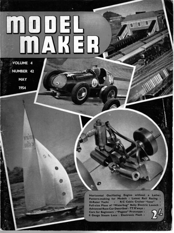
_=VOLUME 4 – NUMBER 42 Horizontal Oscillating Engine without a_ Lathe: Pattern-making for Models : Latest Rail Racing : 10-Rater Yacht : R/C Cabin Cruiser “lone” : Full-size Plans of ‘‘“Waterbug” Baby Electric Launch : Advanced Race Car Described : TT R’ways : Cars for Beginners : “Pegaso” Prototype : 0 Gauge Steam Loco : Electronic Flash :
Fig 1 g SE crass A =\ LWL———- 49.00″ ‘ a) SAL AREAS eiasor ce / Pt S| Saat Aco a Be CS iE YQ) e : Raa Bea SB ner PS JOHN 1 2 HIS LEWIS DESIGN SOME OLD a Fic 2 ig ctass A i= DISPLACEMENT. SAIL AREA B=: $500″ 5$6-O0 LBS oy es =N 1S30° these notes last month we discussed the above water profile of yachts and how changes have been made in recent years towards producing boats which are better balanced. Although above water profile and deck plans are important it is the study of the underwater shape of a hull that determines the boat’s capabilities as a racing vessel. There are many ways of approaching the subject but I feel that it is from comparison that most is to be learnt. Therefore, the diagrams this month show the main features of three “A” class and two 10-rater class yachts. These designs are selected deliberately to illus- trate the points under discussion and do not by any means represent the only answers to the great problem of what is the best form of yacht. It is necessary for the designer to decide, right at the start, what principal dimensions the boat is to have. There are advantages in beam, narrowness, depth and ‘shallowness. compromise must be struck. Some Generally speak- ing when a heavy displacement is called for by the rule, such as “A” class, it pays to go for a narrow hull and the three examples shown have this SERIES WITH COMPARISONS NEW STYLE OF CRAFT Sass LWL : & CONTINUES characteristic. Increase in length 278 gives speed but always results. in loss of sail area. It would take a bold man to prophesy how much more sail area will be reduced in order to obtain longer hulls but I think we: shall not be long before “A” class boats are carrying about 1,400 sq. in. as; an accepted fact and 10-rater 1,000 sq. in. on 60 in. L.W.L. When winds are very light we shall sit in the boathouse drinking tea and planning even longer yachts. Fig. 1 shows a typical “A” class yacht of the early °30’s and is in fact based on a design by the late W. H. Davey. The feature about these designs which was not usual in those days was the narrow waterline beam of 13.5.in., and the profile of the canoe body which was almost symmetrical about the midship section and is almost the arc of a circle from waterline ending to waterline ending. Comparing this with Fig. 2 we see a typical modern “A” boat of 55 in. L.W.L. and of heavier displacement. The L.W.L. beam is 13.5 in. and the cross sections instead of having the nicely rising floors of Fig. 1 have become more U-shaped. This enables the greater displacement to be achieved without having a very deep canoe body. Looking at the profile of the canoe body it will be seen that the run aft is very much flatter than Fig. 1. The increase in L.W.L. helps in this and also a considerable tightening of the curve around
1954 MAY, to the areas of the after part of design (5) and conversely the areas of the after part of design (4) equal the areas of the forward part of design (5). Thus the curve of areas is reversed and the midship section. This flattening of the run is a very desirable speed factor but should be accompanied by a narrowing of the deck line aft. Neither of these designs carry much Q.B. penalty and it is interesting reduction of sail area by 300 sq. in. note a cycle of development is complete. the ee Fig. 3 shows a proposed A” to class where a displace ee es ment penalty is accepted in Meine of the displacement is carried in the heel and an extremely SAIL AREA——1 490°” A large proportion pee le ees | 434 eS without any apparent bilge. Comparing the curves of areas of these three designs shown in Fig. 6 it will be seen that Fig. 1 has a perr fectly normal shape to the displacement curve. Fig. 2 shows a_ considerable in- The curve of Fig. 3 shows SEE RSS soa aii POA LS ae \ OC ot Je \= Ciig 37° S====} a fig 4 oe — Cpe crease in the rate of displacement forwards and despite its increased total displacement is in fact an even finer curve in the after part than Fig. 1. HS ] MESS The L.W.L. beam is 12.75 in. and the hull should be very easy to drive. I feel very tempted to build to a design of this type. ‘ Nf S ee eee Can re P == V sections are very round and f{\\\ W either Fig. 1 or 2 and the = ah fine canoe body is the result. It will be seen that it is both narrower and shallower than ls e ( si BER REE se Les eae ser nce =a order to allow finer lines of the hull. Coa gaeon Fig 3 ee + an even finer run aft and with the reduced displace- of The two 10-rater designs shown in Figs. 4 and 5 ee ee CURVES OF AREAS demonstrate the same trend —____ Spee COE OR ORE, ; in design, i.e., the increase in L.W.L. accompanied bv TM CURVE OF FIG. a an increased rate of displacement in the front half of the sow _— boat. note, It is interesting = =~ ~ _ STERN. to that. by pure coincidence, the cross-sectional] areas of the forward part of esign (4) are exactly equal _sow CURVES OF AREAS oF |O’ RATERS. —<—=— CURVE OF FIG.5. fig? STERN. sinieenmiaieel either : S =e than — x at ike am hull IO RATER WRN - driven the others. canoe body more easily i. ment of the should be a
(WODEL MAKER) DECIMA ‘T is design was undertaken primarily as a test exercise. For some time I have been considering ways and means of making part at least of the design work a more or less geometric process, without any significant loss of flexibility, and Decima was undertaken in order to try out some of my ideas in practice. Doctor Harrison Butler, in his well-known work on cruising yacht design, pointed out that at a comparatively early stage in its development a design could be handed to three or more different designers to complete, and all three finished drawings would be substantially the same. The main problem in systematising the work is thus to crystallise the design at its earliest possible stage to an extent where pure geometric could take over, and complete the design automatically. As many an example years marketed a ago kit a of of design construction and balance simplification, well-known parts model firm for constructing a yacht hull from strips of thin material to cut to a standard pattern. The design was based on concentric circular sections, the profile being also an arc of a circle. In this way. all planks could be cut to the same template, shadows being simplv marked out with a com-’ pass set to the specified radius. A plate-and- ‘bulb fin. plus a skeg and rudder, completed the model. As far as the canoe body is concerned. all reauirements for hull balance were comnletely satisfied. and desion work was reduced to a minimum. I have no reports on the verformance of the vachts. but the idea is of interest as it renresents what must be the ultimate in design simplification. At the same time. however. such a method imposes the greatest inflexibility, since the result is always an elongated snhere, onlv the extent of elongation and the flotation plane being controllable. A symmetrical curve of areas of stereotvned form is also obligatorv. and not manv vachtsmen would annrove of this. The method is, however. being develoned in a refined form bv Mr. W. G. V. Blogg, and some interesting results have alreadv anneared. In general, it can be safely said that the ereater the simnlification. the less the flexibility. How much flexibility is in fact needed, is a moot point—possibly models require less freedom in design than manned-up craft, and perhaps 284 AN INTERESTING YACHT FOR EITHER 10-RATER REGISTRATION ORAS AN X-CLASS BOAT (U.S. CLASS) DESIGNED BY D. A. MACDONALD many of our likes and dislikes in hull forms are in the long run no more than personal fads. The system I eventually evolved, and used to produce Decima, is largely geometric, but the essential features of the design are determined by what it is now correct to call artistic methods. The essential features to which I refer are, first, the shape of the midsection, and second, the distribution of buoyancy. One line is required to draw the section share: the distribution of buoyancy is fixed by two further lines, and a fourth line is required to ensure correct heeled balance for the canoe body. The system can, therefore. be called a “fourline” method since four lines emnirically determine the shape of the hull. So far as I can see at present, the variety of hull forms which can be produced is almost unlimited, but I have not yet explored all the possibilities. As a first test of the system it was decided to design a hull of fairly normal form, with natural overhangs. The X-class, being the least restricted in hull design, was an obvious choice, esnecially in view of a growing interest in the class in this country. On the other hand. there is at present no organised racing for the class in this country, so the design would not have much of a try-out. My second choice was the 10-rater class. which at present is covered bv quite a spate of new designs. It was eventually decided to make the new design a dual-purpose craft, 10-rater or X-class. to: rate As as such. it either a is at least something fairly new, and should be of most interest to the keen and prolific builder who is looking for something out of the ordinary, for his next construction effort. It will also enable him to dabble in the X-class with a craft which he can register as a 10-rater, and which should prove fully competitive in its class. I must here point out that the M.Y.A. rules do not allow a boat to be registered in two classes, so that if the X-class were adopted in this country, the owner would have to decide in which class he wished to compete, and register the yacht accordingly. For the benefit of those unfamiliar with the X-class rule, the essential details are shown 1n the appendix. For the purpose of the present description, the main features are as follows:— (1) Practically no restriction in hull form
MAY ae or dimensions (other than the undesirable hull types specifically prohibited). (2) A maximum sail area of 1,000 sq. mm. measured on the same basis as 1954 rite ez 1 ar the ao § 14 aR as ai sail. The latter will rate the same in both classes provided the batten and roach limits for the X-class are not exceeded. but a boat registered and competing as a 10-rater may take advantage of the higher limits for this class. and shin an alternative mainsail to the X-class limits for X-class exverimental sailing. In any case, I do not think the difference in the limits would result in any significant difference in nerformance under normal conditions, with a hull of Decima’s type. As a first approximation, 85 per cent. of the enclosing foretriangle area in the 10-rater class will equal the area of the iib itself, although in practice it is a fairly tight squeeze, and no valuable foretriansle snace can be wasted in clumsy fittines if the same jib and forestay points are to apnlv to both classes. Ideally. therefore. 5 || LHONVHG NOLS WOOLLNG ONIDWdS ow ASVTIVE ONIN Bz IVLOL @ OL _9 ANIvd A ae LS Ee eae ON a WA eS AYW Od O3SN 3a Xx pied [| | | | } LT 2 ie NOILISOd AVLSSYOd SIKL 3 a 3 @ | A. a ae i) ULI ry 4g bal e. 88g Gsvia z $66 W101 e Sp Og . © x) Vauv tvs” or gee: 9 OOL ' ee ear NIV BS RS Tae NEet = The fin and skegs are conven- 285 > im bop “SIVENIVA – SNSLive Tvs automatically. tional, the former being faired carefullv into the canoe body. and disposed to maintain. with the skes and rudder. a sufficientlv accurate overall metacentric balance. A hard choice had to be made between strict adherence to the geometrically develoned form. and deliberate distortion (e.g. snubbing the forward L.W.L. Endings) to achieve extra unmeasured sailing length. It was decided eventually to give the method a fair trial and to accept no compromise, the geometric form being maintained on a 60 in. measured L.W.L. However, the fine entry does allow considerable reduction of measured L.W.L. by blunting the g a U862 sonxey of the work was then allowed to comnlete itself Fa ia St a hich aspect ratio. From this data. the four controlling lines for the design were set out and the remainder z 9 5 W SNITH3LVM 9 I could design for a 60in. L.W.L. and 1,000 sq. in. measured by either rule.. However. provision is made in the design for reducing area of 1,000 sq in. and stability adequate for Pe > a towards a moderate proportion of jib to main- this sail area carried out in a sailplan of fairly FE RG Boe fest =e as M-class. (3) No spinnakers allowed. The main restriction is thus the sail area limit, and the ban on spinnakers will tend the measured L.W.L. slightly. if the builder requires it as a safety measure. The design data for the hull thus resolved itself as follows:—A measured L.W.L. not exceeding 60 in., the displacement and type of section being suitable for easy pronulsion by a sail 3, ar 2)
MODEL MAKER leading edge of the profile. Up to 4in. reduction, the distortion of the profile curve is not appreciable, and it is scarcely detectable at ¢in. reduction. Dotted lines on the plan indicate the modification for 59.75 in. measured L.W.L. The choice of whether or not, and if so, how much, has therefore been left to the builder, as opinions differ among enthusiasts as to the virtues of the blunted leading edge. Theoretically it is beneficial to form resistance, up to a few per cent. of maximum L.W.L. beam; my own experience is that within this limit it appears to have, at any rate, no harmful effect in practice. I should be very pleased to hear from any enthusiast who undertakes the building of Decima, and especially interested in reports on performance. Acknowledgements. The author’s thanks are due to Mr. A. F. Hill for valued assistance in checking and tracing the design, and to Mr. N. D. Hatfield for information on the X-class rating rules. APPENDIX Rating Rules, American X-class (abridged) Hull Unrestricted as to the following:— (1) Scantlings (2) Material (3) Displacement (4) L.W.L. (5) L.O.A. (6) Beam (7) Draft (8) Freeboard (9) Tumble-home Restrictions :— (1) Punts, prams, forward transoms prohibited (2) Garboards:—Hollow of garboard at midship section shall be not less than an arc of a circle with 1 in. radius (3) Weight of lead ballast shall not be changed during a race or series of races Prohibited:— (1) Sliding or adjustable keels (2) Metal fin keels (3) Centre boards (4) Lee boards (5) (6) (7) (8) (11) Bilge boards Bowsprits Overhanging Rudders Moveable or shifting ballast Outriggers or pontoons Rig Unrestricted as to the following:— (1) Any type of rig allowed provided batten limits are not exceeded (2) Alternative or smaller rigs allowed provided total sail area is not exceeded (3) Height of rig, mast or forestay is not limited (4) Mast or spars may be of any type, section or material Restricted as to the following :— (1) The greatest diameter of mast and spars is limited to 1 in. (2) Headsticks or headboards shall not exceed 1 in. across base (3) Wire or other stiffening shall not be put in leach or foot of sails. Corners of sails may be reinforced with the same material as the sail (4) Battens shall divide the after leach of the sail into approximately equal parts. Mainsail battens not to exceed four in number: upper and lower battens shall not exceed 4in. in length. Intermediate battens not to exceed 5 in. in length. Jib battens not to exceed 3 in number, each not to exceed 3 in. in length (5) Roach of sails not to exceed 2 in. Rounded foot of loose footed sails not measured. Prohibited :— (1) Spinnakers (2) Reaching or Genoa jibs ss = PATTERN MAKING FOR MODEL be sandpapered and the bearings housings, panhandle lug. etc., be added. Machining will be simplified if you add feet to the bottom so that the casting will rest firmly on the machine bed. Before the final finishing it remains to add the fillets round the bosses, bulkheads. etc. The fillets can be made of either “Brummer” ‘stopping (obtainable from any ironmongers) or beeswax. “Brummer” is also very useful for correcting any mistakes in carving, and is much easier to use than plastic wood. After a final sandpapering the pattern is ready for painting. This is very important, its purpose being to make it smooth and imper- vious to the moisture in the sand used for moulding. At the same time it makes it easy to withdraw it from the mould. The professional finish is usually shellac varnish, made by dissolving orange shellac in alcohol. but if any red cellulose is available this will do quite well. Shellac has the advantage of adhering well to any wax used in fillets. The procedure using either shellac or cellulose is very similar. The first coat applied Taises the grain in the wood, which, after the 286 CARS (Continued from page 259) coat is dry, must be sandpapered again until smooth. At least three coats should be used, sandpapering as necessary between each. Incidentally, there is a standard system of colouring patterns to indicate unfinished surfaces, surfaces to be machined, core prints and so on, but for our purpose red is as good as any, indicating “surfaces to be machined”. The pattern is now ready for the foundry and it only remains to specify the material required. This is likely to be dictated by the alloy which the foundry is using for its ordinary work, since our one-or-two-off jobs are not big enough for a special melt. The common alloy is D.T.D. 424, which is quite satisfactory for most cases and machines well. The other types of patterns met with when building model cars—spur gear brackets and gear boxes—are relatively straightforward and need not be dealt with at length. Generally speaking, it is not necessary to put any draw on them, as they are so small and simple that the moulder will be able to “rap” them free easily. Diagram 9 shows typical construction of these types.


