- Dovercourt Presents 36-In. Restricted Class National Championship.
- Pond Side Aids. By ‘Cepheus’.
- Model Yacht Designing, Part III Hull Balance. By John Lewis.
- The Problem of The Inclined Rudder, Suggestions That May Help to Make The Full Keel Boat More Popular. By A. Wilcock.

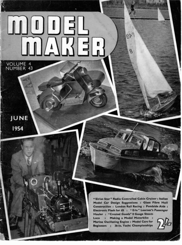
VOLUME 4 NUMBER 43 i “ Sirius Star” Radio Controlled Cabin Cruiser : Italian Model Car Design Suggestions : Glass Fibre Hull Construction : London Rail Racing : Pondside Aids Electronic Flash for £8 : ‘ Eila” Learner’s Passenger Hauler : “Crested Goods” 0 Gauge Steam Making a Model Motorbike : : Marine Oscillating Engine : Model Cars for Loco Beginners : 36-in. Yacht Championships (mr |
OneL BO. VER C.O UF R.T PR-E:. E Net S s 3 ee Oe MAKER 36 wn. RESTRICTED CLASS NATIONAL Macdonald proved a convincing winner of the 36in. restricted class yacht championships held at Dovercourt. He was sailing the latest —if not the ultimate—development of H. B. Tucker’s famous “Duck” designs in the shape of Quackie III. Due to a series of misfortunes such as a warped keel, final tuning up virtually took place during the contest, when with every heat the boat seemed to go better. Close on its heels, leading in fact for the first two days of the contest, was Mac’s older Quackie 1, now in the capable hands of young Barry Barnes, who also has his original Saida Marblehead and, we are told regularly beats the original owner’s present boat on the Rick Pond with it. Third came Escapade skippered by A. Hill of Clapham, which lost second place only on a resail after tieing with Quackie I. Another young skipper sailed very capably into fourth place with his Duck boat Cantania. The entry may be considered a_ person al triumph for veteran designer H. B. Tucker whose Duck designs provided seven out of Heading: “Mac” adjusts Quackie III, seen here in her top suit. Note omission of keel continuation to rudder as designed in Quackie II. Below, left: Interesting clink-built boat Kitrywake II. Centre: Gazelle sails against A. May’s Zephyr IV. Right: A nice shot of Stella sister ship to XOOZME 320 y+ R ELURNING to the contest arena after a necessary Coronation Year absence D. A. — ee tiene CHAMPIONSHIP
JUNE, twelve boats, though we are sure he would be in agreement with us in deploring what seems a complete absence of original thought on the part of any other designer! Lowly placed but interesting Kittywake IJ from Birmingham showed the most courageous departure from the rut with a clinker-built hull to the skipper’s own design. It was beautifully made, but suffered from far too heavy a bow section. We would certainly urge S. Rollason to press on with his ideas, however, for we are sure it has possibilities. Vane gears seem to have definitely established themselves in the 36 in. class, with fifty per cent. of the entries so equipped, thanks, perhaps, to the little half-size Mullett vane now on the market for this size of boat. Winning boat Quackie III is closely in line with Quackie I, the original Duck, and its successor Quackie IJ, but has been modified for Vane gear. We are fortunate in having the designer’s own comments from which to quote, and give them below in abridged form: “The reason I re-designed her was that in 1952 she was seriously challenged by a sharpie with vane which helped her in a very tricky reaching wind . . . After consulting with Macdonald, I decided to make other changes. I have slightly fined her “duck” bow without impairing its efficiency. As the use of the vane meant slightly less S.A. (though still nearly 900sq.in. in top suit!) XQOQOZME starting against Quackie III in bottom suit. Cantania, young R. Pritchard’s “home” entry which sailed so well. Note deep chord of vane feather employed. The well-placed Escapade has a board with Zephyr IV in the foreground 321 1954 I used a rather deeper but easier section, and borrowing some ideas from Lynx (H.B.T.’s A Class boat sailed by Mac) moved her C.B. forward somewhat, shortening the entry and lengthening the run.” It was noticeable in sailing that Quackie III had a quite different wave formation from the other ducks, some of which may be attributed to slight variations in building, but even compared with Quackie I it was obvious that the new boat was coming through far more cleanly, while her acceleration, when a puff of wind came was, in H. B. Tucker’s own words “just as if a bomb had exploded under her tail!” As to the contest sailing, a glance at the daily totals shows that over half the entry were within striking distance after the first day’s sailing. On the second day, light winds fell away until there was a flat calm by midafternoon, and the full day’s programme cut short. A noticeable feature is that clinker-built Kittywake II was equal second on that day’s work, three points ahead of the winner, who had little or no experience of his new boat under light airs. Then surprisingly, on the final day, everything went wrong for young Barry Barnes who could only amass twelve points, while Quackie II skated ahead, taking a critical five points from Quackie I to come into the lead for the first time. | Meanwhile both Escapade and Cantania had been quietly climbing through the field to remain dangers until the last few boards put the issue beyond doubt. On the purely constructional side, Quackie III was beautifully built by Levison, who acted as mate to Mac, and sported the terylene sails first tried out on Lynx two years ago. These
Quackie III nearly shows head-on a view. nice wave On the formation right: Barry are unaffected by water, do in this Barnes’ Quackie I makes light of her years not crease and —lazy man’s deligh — can t be rolled up wet and forgotten without evil results XQOQZME and Stella were identical ducks built by club-mates with a polished wood finish, and a dark mahogany band, popus larised by Levison. Levison by the way, was responsible for building four of the boats, the others being, Escapade, Sprite and Gazelle. No sharpies were in evidenc e this year, which is somewhat surprising after the good showing put up last yeat by Lancet and others to Tommy Lance’s simple design. Dovercourt as the host club are to be congratulated on a smoothly organised event in which the local authorities plaved an active part by the presence of council- lors at the start, during the contest and a__—.. the prizegiving. RESULTS | Ne | 849 | i ii | aerate Quackie lil Club | Designer | Steer- * – | D. A. Macdonald | M.Y.6m0.A. ing Points Ist Day |2nd Day) 3rd Day Total | Place 612 | Quackie | | B. Barnes Tucker | South London v 33 18 Tucker 32 | ws B | 35 22 12 | 843 | 69 Escapade | | A. Hill | Clapham Tucker B 27 19 23 | 69 836 Cantania 3 | R. Pritchard | Dovercourt Tansley V 27 10 28 «| «(65 4 664 XQQZME B 24 15 20 | | 59 5 842 | Jilo 665 Stella W. Mayhew 672 Media G. E. Swinyard | Felixstowe | | 2 (after) | | 864 | Zephyr IV | L. C. Chapman | J. Watts | A. May Norfolk and Norwich | Danson Tucker | Littlejohn | Vv | Tucker B 27 144 16 | 574 6 | 18 16 23 «| «#57 7 | Bis”) 26 9 18 || 53 8 Norfolk and (after) || Finch –216 18 9 43 9 Dovercourt Tucker Vv Norfolk and Norwich Daniels | Norwich B | | 709 | Gazelle | 7. Chapman 27 64 5 | 384 lo f 851 = Ss Rollason ‘ | Birmingham 603 | Sprite Rollason _E. Ladbreoke | v 6 | Dovercourt 21 9 | 36 Tucker il lov 4 Il 1s. |. 3p Kittywake If Plan view of Quackie Ill, latest Duck from the Tucker board. We understand that further Ducks in all sizes may be show the expected their not paces too future 322 to in distant q
neatest job make the head in three pieces and silver solder. The second type of head (see drawing) looks less _professional, but on the other hand is easy to make and involves no lathework. Moorings When the models are not actually under way or in use, or when you adjourn for a glass of boatman’s reviver, the boats can be quite safely left out of reach of itching young fingers by rigging up a line of realistic-looking moorings some feet away from the bank. Soldered up food cans or turned wood blocks make the buoys, and they are provided with a ring on top and a wire loop underneath. A glance at the drawing will show how the mooring is arranged from the bank. The special sinker is thrown out on an endless cord, the other loop of which is secured to a stake on the bank. The whole assembly of ship, buoy and buoy rope is then attached to this cord by the buoy rope and gently pulled out into position pulleywise. The special sinker was designed so as tc allow an easy passage of the cord no matter which way up the sinker landed on the bottom, and to give a good grip on slippery clay. The “double triangle” is of lead with brass strips joining the two sides and forming the centre ring. Bend up two triangular moulds from tin plate, fill them with lead, and push in the brass centre part while the metal is still molten. THE time is again fast approaching when good rest-loving citizens living near ponds, lakes and rivers will be brutally awakened on Sunday mornings by the crackles, pops and whistles of the local boating section going into action. Race-round-the-pole enthusiasts operating in ideal ponds and equipped with waders can give a quiet chuckle here and not worry about the devices shown in the accompanying photos, but for those of us who operate prototype craft in restricted, deep and overgrown pools, in competition with swans and rowing boats to seaward and hordes of heavy fingered small boys in the dockyard. … The Boathook This useful weapon gives your arm an extra 12 ft. reach, and will soon prove its worth at the pondside. The handle is made from selected strong garden cane, and is in three or more sections each about 3—4 ft. long. Brass ferrules are chosen to be an easy sliding fit on the removable member and are the next section. The head follows full-size practice and for pushing or pulling. For fixed tightly to of the boathook is equally useful the lightest and Marker Buoys These buoys for steering competitions and the like can be made from almost anything that floats. Their only cunning feature is the elastic mooring cord. This is arranged to be slightly in tension so that wind and waves won’t be able to push it around willy nilly as on a fixed-length tether. A _ painted aluminium flag on top and yellow and black checkers make the buoys stand out from the other flotsam like red, white and blue geese in a flock of seagulls. Retaining Boom Many ponds and lakes have well-marked danger areas for models such as overhanging trees, bushes and in some cases racing mill Heading: Boathook in use retrieving a cabin cruiser from deep water Left: Close-up of boathook head and ferrule joints 328 ;
JUNE, MARKER BUOYS WEED RAKE 1954 6’ BATTEN 6″ WIRE NAILS AT 4″ CENTRES ALUMINIUM FLAG “a LEAD BALLAST = ee LONG HANDLE. 20″ UPWARDS RUBBER MOORING CORD BOATHOOK CONSTRUCTION LEAD OR STONE (FERRULE JOINTS) I B.A. BOLT CANE FIXED MEMBER REMOVABLE MEMBER Model steam yacht moored to a buoy in RIVET HEAD OF BOATHOOK ( 1.) heavy weather, with chequered marker buoy in background Below: A 100 ft. boom supported by buoys. The rope is taut and about 2 in. from the water eee ey POINTS dete te outflows or even children’s paddling pools. To prevent boats from straying rig up a boom FILE FROM %”ROD ALL BRASS of buoys; then, even if the boom is rammed full speed ahead by some hefty vessel, it just soaks up the boat’s inertia like a soggy punchball and turns the boat’s head back to seawards with no damage. To make the boom, paint cans are loaded with wet sand or lead so as to have only about lin. freeboard when dropped in the water, and are fixed on by tags soidered to their lids to a length of ordinary }in. diameter rope. Launch the buoys all together, tow the boom into position, and make the ends hard fast. Among the other troubles that worry the boatman, that of weed seems the most prevalent. If you can store a weed rake near the pond, it will well repay your trouble in making it. A 6ft. length of batten attached to a long handle is drilled at 4in. intervals and studded with curved 6 in. nails. i. 22+ ENDS FILED TO HALF ROUNDce & SOLDERED “a” BORE TIGHT FIFT ONN CANE INTO BRASS FERRULE SIMPLE TYPE (2). amie a ai coef ‘ 5 Ca o BEND FROM “se” BRASS WIRE | & SOLDER TO BRASS FERRULE MOORING BUOYS, SINKER , & MOORING FROM BANK. BUOYS USUALLY SUBMERGED TO ABOUT HALF DEPTH. LENGTH: ABOUT | X DIAM. Se COLOUR:— USUALLY BLACK ALTHOUGH DISTINCTIVE : 4 LEAD WIRE LOOP SINKER TSEE TEXT) L bok ig? sIDES—— MOORING 329 | | or apo Com
one th Medel ee im 8 } Wak oe | ia Se oe i | see De ae IN PART Ill OF HIS DESIGN SERIES JOHN LEWIS DEALS WITH HULL BALANCE, UNBALANCED ” “ N the first two articles we discussed the above water profile, canoe body shape and distribution of displacement of typical model racing yachts. This third article must, therefore, deal with such things as hull balance, shape of -fin keel, position of centre of lateral resistance and other features which are always the subject of considerable discussion between model yachtsmen. One of the beauties of yacht designing is that so many things are a matter of personal choice and there are few fundamentals about which one may be dogmatic. Let us deal with balance first. This word occurred several times in the previous articles and the general trends in design tend towards producing boats possessing better balance. By balance we normally mean that the yacht sailing at varying angles of heel does not change its course. There are two principal causes for lack of balance. Firstly, the centre of buoyancy should not move excessively from its upright position when the yacht heels and secondly the fin keel should be designed so that the stream of water surging up the side of the hull from the garboard region is not impeded. Calculations for finding the movement of centre of buoyancy are simple and it is fairly obvious that if the C.B. moves aft then the hull lines must be modified by fining down above water in the after section or the underwater forward sections. Naturally, by filling out the underwater sections aft and the above water section forward the same result is obtained. SST eT 334 SHAPE OF FIN KEEL & C.L.R: The checking of hull balance by this method concerns the canoe body only, and ignores any effect of the fin keel. Generally speaking satisfactory results are obtained providing no unusual shape of keel is employed. A more compiete balance method is that devised by Admiral Turner, commonly called The Metacentric Analysis. A very detailed and simple explanation of this is given in that excellent book “Cruising Yachts, Design and Performance” by the late Dr. T. Harrison Butler. — Although one may take great care in achieving satisfactory balance by either of the above methods they are, after all, only checking static conditions. A yacht travelling in a seaway is subject to dynamic forces and it is difficult to ignore the effects of wave formation, leeway and differences in pressure exerted on the hull. Another disturbing thought is of the boats whose designs completely overlook any idea of balance, as we know it, but whose performaiices are adequate to win races against the best in their class. These boats cannot be ignored or condemned off hand. I believe that we have a lot to learn about the art of producing a satisfactory yacht, but I would always be very wary of building to a design which did not comply with one of the static methods of checking balance. Let us now look at the design of the fin keel. Here again is a subject about which one should keep. an open mind. The two main uses for the fin keel are to prevent the boat making excessive leeway and to support the lead ballast. These functions need to be satisfied with the smallest area and the deepest draught loa) BALANCED HULL SHEWN IN SOLID LINE
JUNE, safe enough. Designs (2) and (3) both illustrate keels of greater thickness than usual pracThere is a great deal of scope for tice. possible. It is very doubtful whether it is wise to exceed 12 in. draught considering the shallowness of the average model yachting experiment in keel design. The position of the keel under the canoe body is important but the usual thing is to start the leading edge at a point 30 per cent. lake. The problem of area requires quite careful thought, however. We all know that the wetted surface of the yacht should be kept to a minimum as this is so important to perforI feel that designers mance in light winds. generally err on the large side when designing keels. This, of course, is preferable to having the boats sagging away to leeward for the sake of a little lateral area. However, it has been my experience with every 10 rater that I have owned that 2 good hefty slice off the after edge of the keel has resulted in improved all-round performance. Not all these boats were of my own design or build. Looking at the rough designs illustrating last month’s article it is interesting to compare their areas of lateral plane. of the L.W.L. back from the forward waterline ending. One frequently hears arguments as to the correct position of the Centre of Lateral resistance but I have never heard anyone say just where this should be placed. Of course, it is quite easy to calculate where the centre lies on the plan. However, as soon as the boat starts moving through the water the C.L.R. moves forward. There is no easy way of finding out the amount of movement nor the rapidity of its travel. I feel that as the C.L.R. never lies where calculated when the boat is in motion, it is just a waste of time working out the figures. Fig. 1 has 112 sq. in. with 1830 sq. in. S.A. »» 2has 145 sq. in. with 1530 sq. in. S.A. » 3 has 115 sq. in. with 1490 sq. in. S.A. : © 1954 It seems logical to me that there should be some relationship between sail area and area of lateral plane. Design (1) was a satisfactory performer to windward and design (2) is not abnormal in its amount of keel area, and yet its lateral area is 33 sq. in. greater than design (1) and its sail area 300 sq. in. less. Cutting off the after edge produces a keel as shown in design (3). I prefer this keel of the three but some designers would consider it to be too short to maintain steady steering. The shape of the keel is also important and for general purposes I have found that the conventional leading edge rake of about 45° with a bottom edge parallel to the waterline is the best. The shape of the after edge does not seem so important providing the entire keel is not too long nor interferes with the garboard stream of water. By variation of the after edge, control of wetted surface is easily obtained. I prefer a shorter keel with a nearly straight rear edge as it makes it easier to tuck away a little extra displacement where no harm is done. This really leads up to a third use for the keel, in that in classes of yacht where a heavy displacement is called for, the keel can be used to achieve the required weight and assist in maintaining an easily driven canoe body. The thickening of the keel is a relatively new approach and we do not know yet how far one may go before serious increase in resistance occurs. From my own practical experience, I think that a thickness to length ratio of 6 : 1 is However, the position of the C.L.R. can be of use in helping to place the sail plan over the hull. Then the centre of effort of the sails is put a certain distance in front of the C.L.R. As both C.L.R. and C.E. of the sails move forward, when the boat is in motion to some unknown position it is very difficult to say just what their relative static positions should be. The correct placing of the C.E. is also largely a matter of experience and instinct. Looking at the diagrams with this article we see that Fig. A. illustrates how the canoe body of a 10 rater has been brought into balance. The dotted lines show the sections before (Continued in page 355) 335
MOEN MAKER THE PROBLEM OF : ‘ ‘ 1 ‘ 1 ‘ ‘ ‘ 1 t i ; ! 58, Le ad SUGGESTIONS HELP TO THAT MAY MAKE THE FULL KEEL BOAT MORE POPULAR BY 2 hee inclined characteristic rudder is of the full the days of keel yacht. In Braine Steering, a quadrant set at an angle to the deck was not very convenient but it could be made to work providing the rudder inclination was not too great. The age of vane steering makes new demands on the steering mechanism, three of these being (1) a vertical pintle for the vane gear (2) great freedom of movement in the whole steering mechanism and (3) ability to balance the steering system. It is the purpose of this article to describe a mechanism which the author has made and used _ successfully in the hopes that its description will foster more designers of the full keel boat. A glance at almost any full keel boat and its sail plan shows immediately that the vane gear proper must be placed well aft of the head of the rudder tube to clear the main boom. The plain push-pull linkage described in October 1952 Mopet Maker seems obviously the simplest method of doing this but the fact that the rudder post is inclined calls for special treatment. The inclined rudder post also gives rise to any operating arm attached to it describing an arc inclined to the deck which if placed above the deck must be relatively tall and unsightly, if it is to give adequate clearance. The fitting of the linkage mechanism below deck as shown in Fig. 1 is recommended. This has the advantage that small weights for balancing can also be shipped below deck. A A. WILCOCK requirement of M.Y.A. Rules however in such cases is that a hatch or removable inspection cover must be fitted to allow for inspection. This however can be very neat, well seated and weather proof and is almost a requirement for one’s own maintenance inspection from time to time. Perhaps the greatest drawback to the arrangement is the hole for the emergence of the vane column, but if this is protected by a trunk as used on a mast slide it does not present any real danger. Turning now to the details shown in the figures. The rudder tube is terminated below deck leaving a gap of between }in. and lin. This is well above the water line either upright or heeled and water is not going to enter the hull this way. To keep friction to a minimum the rudder is swung between pointed pintles top and bottom. That at the top should be fixed to a deck beam—put there for the purpose if necessary: a bearing at the top of the rudder tube is not recommended. The arm for operating the rudder is fitted to the post between the top of the rudder tube and the top pintle but to give adequate movement must be cranked downwards. To enable the rudder to be removed the fixing of the arm must be only semi-permanent and the detail shown in Fig. 2 includes a miniature cotter pin, not unlike those used on bicycle cranks, which will be found to be very satisfactory. The second arm is for a counterweight since only one arm with the addition of the gimbal joint and linkage rod would fall by gravity and give permanent helm. Both arms can conveniently be 6 B.A. threaded rod screwed and sweated into the fixing block. The cotter pin is best made from something stouter say $in. rod threaded only where required or 4 B.A. rod filed for the wedge surface. Fig. 2 also shows the gimbal joint made of say }in. dia. rod drilled out at the ends for the springy stirrup and through the centre and tapped to fit on the arm. The counter weight on the opposite side should slightly exceed the weight of the gimbal as it is also balancing some of the weight of the push-pull rod. The push-pull rod can conveniently be a cycle spoke and a nipple be drilled to take the stirrup of 354
JUNE, springy wire which enables it to be sprung on to gimbal. The ends of the stirrup should be pointed to give an easy bearing on the bottom of the drill holes in the ends of the gimbal. Now for the vane pintle mechanism. The details of this will be apparent from Fig. 1. It consists of the pintle proper mounted on to the keelson of the boat and arranged to be vertical with the boat in normal trim. It need only project through the deck by 4 in. to # in. It is surrounded by a clearance tube carrying a plug at the top for the pin point bearing and a centering washer at the bottom. Below deck this carries three arms, two lying across the boat, one to port and one to starboard and the third one aft. In Fig. 1 the port arm carries the end of the push-pull rod by a simple linkage, 7.e. the rod which is circular has its end turned to an eye fitting or peg on the arm with just an easy clearance. This gives an “easy” joint, the eye on the end of the rod making two point contacts, one to the peg and one where it rests on the flat arm. At the same time it allows for the push-pull rod up and down movement at the rudder end without causing binding at the vane pintle. The other two arms should be of 6 B.A. rod and are again used for counter weights. I can hear the weight addicts saying all this is going to be heavy. This is not so. The weights used on the author’s model were probably about }o0z. each and when adjusted the boat could be heeled 45° to port or starboard and 30° fore or aft without the rudder moving and as evidence that this was not stiffness in the assembly, the withdrawal of a weight or serious maladjustment told a very 1954 On the top of the tube above deck is mounted the vane gear and an arm to carry a light centering line as well as indicate rudder movement. The arrangement shown allows for the usual commercial type of gear to be mounted. It is convenient to use the arm for the centering line to also limit the motion to say 40° either side by means of stops. In addition to preventing the crossed link (push-pull rod) below decks, crossing over, these stops also give something firm against which to turn the vane assembly, as is given by the connecting pin coming to the end of the tiller arm slot in a normal vane to rudder linkage. Finally the operations of balancing are as follows. Since the vane self-tacking mechanism itself should be balanced alone (see April 1952 MopeEL Maker) it is only necessary here to consider the rudder and linkage mechanism. The rudder being inclined will, when out of water, fall into a neutral position with the boat upright. When in water its buoyancy will lift it to one side or the other. The linkage arm will tend to fall and counterweight A is used to neutralise this thus the first stage is to adjust counterweight A for both weight and leverage with the boat out of water, on an even keel and upright. The counterweights on the vane pintle have no effect at this stage. Counterweight A can now be locked in position with a nut. The boat can now be put in water and counterweights B and C adjusted. B primarily affects balance in heeling while C balances for fore and aft trim. A little experimenting will soon give perfection in balance over wide angles of heel and trim. different story. ——_— — es MODEL YACHT DESIGNING (continued from p. 335) balancing and the solid lines show the result of filling out above water forward and_ fining down after. As a matter of interest the movement of C.B. aft is 0.12 in. in the case of the solid sections and approximately 0.27 in. aft in the case of the dotted sections. The following four diagrams show some typical fin keel profiles as applied to the 10 rater class. Their characterictics are applicable to the other classes also. Fig. B has a keel my preference is because of its efficient appearance. It has proved to be very efficient in practice too. Type “D” is one that I have no personal experience of, but it does save wetted surface where leading edge and after edge is about parallel. Many successful yachts have keels of this type and there is much to commend it, except that the lateral area may tend to be too great. Fig. C. shows a keel with a much shortened fore and a nearly vertical after edge. This is my favourite and does save some wetted surface over the (“B”) type although I must admit that 355 by virtue of the severely cut-away after edge. The “Flying Fifteen” type of boat uses it but I would prefer to try it out on a fully balanced hull before passing much comment. Fig. “E” shows a variation on the “C” type but having rounded curves is not so stark in appearance. I doubt whether there is anything to choose between them except that type “C” would enable the lead to be carried lower. These notes on yacht design are by no means the complete story but if they have been of interest and possibly started some fresh discussion on design then they will have served their purpose.


