- Circular Arc Hulls, Provocative of Much Thought.
- Vane Without Pain, Vane Gears and Their Use Part 2. By H.E. Andrews.
- Windstar, A New 6-Metres Design. By H.B. Tucker.
- MM Class Yacht Plans, Sails and Rigging.
- Tucker’s Topical Talks, Don’t Shoot the Pianist. By H.B. Tucker.

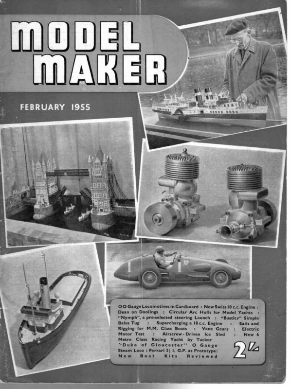
OO Gauge Locomotives in Cardboard : New Swiss 10 c.c. Engine : Dean on Doolings : Circular Arc Hulls for Model Yachts “Nymph”, a pre-selected steering Launch Balsa Tug : Metre Class “Duke of : : Vane Gears Airscrew-Driven Racing Yacht Gloucester’’ by O Ice Sled Tucker Gauge Steam Loco : Ferrari 2} I. G.P. as Prototype: New Boat Kits Reviewed : _ ‘“Bustlcr’” Simple Supercharginga l0c.c. Engine Rigging for M.M. Class Boats Motor Test : : 5. Sails and Electric New 6
i | MODEL MAKER} =e Admiral Turner ! is with the deepest regret that we report the death of Engineer Rear- Admiral Alfred TURNER on January Sth in his home at Lochsheath, near Southampton, at the age of 74. “The Admiral” as he was known from the Clyde to Hobart and from New York to Capetown, was famous among yachtsmen everywhere for his theory on the Metacentric Shelf. This was first developed and applied to model yachts in the late 1920s, and from 1931 onwards his designs were pre-eminent amongst model yachts, producing such notable winners as Tinker Bell, Rhapsody, Seri, Aktis, Lady Nell and Naiad. The loss of Admiral Turner will make it hard, if not impossible, for the Model Yachting Association ever to replace him with a President of his calibre, for not only did he design magnificent boats, but he ‘also took an active interest in the administration of the Association, and of the International Model Yacht Racing Union, and was an ever present spectator at the principal races of the year, when his advice and encouragement was always at the disposal of model yachtsmen. THE showing of Samoena in the an aspect of model yacht design which will no doubt be a controversial issue for years. We refer to the circular arc hull in which the canoe body consists entirely of concentric circular sections, or, rather circular’ sections the centres of which are on a straight line parallel with the waterline, allied with a true arciform profile. (Fig. 1). A hull of this form will remain constant in shape at all angles of heel and the centres of buoyancy of all sections remain in a straight line. The curve of areas of the submerged body is actually about halfway between a versed sine and a trochoid curve. (The prismatic coefficient works out at 57 per cent.). If the fin is placed nearly below the centre of His achievements as a designer must not, however, be allowed to overshadow a distinguished career in the Royal Navy which he joined in 1897 and served in a variety of capacities, including Engineer Officer of the Flotilla leader Abdiel, famous for her mine-laying expeditions in enemy waters in the 1914-18 war. He retired in 1932, but was recalled in 1939, and from 1941-45 was Repair Overseer in the Thames. His later years were marred by health, and he suffered the loss 1954 A Class Championship focussed attention on PROFILE RADIU: LINE OF CENTRES. illby fig] amputation of a leg barely twelve months before his death, but he weathered this severe operation with all the courage and fortitude expected of him. SUBTENDED We salute the passing of a very gallant gentleman, and extend our sincerest condolences to his family in their bereavement. 76 SUBTENDED ANGLE.
FEBRUARY, ‘1955 PROVOCATIVE OF MUCH THOUGHT IS THIS BRIEF SURVEY OF > CIRCULAR ARC HULLS buoyancy, the balance of the whole body will be in accordance with Admiral Turner’s theory of good balance; by careful attention to the fin waterlines it should be easy to arrange the fin position so that while its C.B. is very close to the vertical through the body C.B., the f greater portion of the side area is in fact aft of this vertical. Naturally, circular cross-sections could be allied with a profile more normal than a true arc; many designers consider that a straight run is essential to allow a boat to plane well. So far, three boats have been tried with arciform profiles—Samoena by Fred Douglas and two Marbleheads, Arcady and Manatee, both from Guy Blogg’s board—and each of these craft performs equally well on or off the wind. Samoena, in the A Regatta at Gosport, actually took windward points from all the boats ahead of her except Moonraker. The main character of the hull developed depends primarily on the relative height above water of the line of sectional centres (Fig. 1.) i.c., On the size of the angle subtending the main section (Fig. 2). A large angle produces Seeing is believing, and the photograph on the opposite page shows Samoena, like Sterope, rising from the waves. Note maintenance of trim. That Samoena keeps good company is shown by the pictures on this page (above) with Revanche, 1954 “‘A” winner, and (below) with Arabesque, 1953 “A” winner a deep, narrow – sectioned hull, and a small angle a wide, flat hull. It is interesting to note that Fred Douglas used a 67 degrees half subtending angle on Samoena, while Guy Blogg used 66.4 degrees and 60 degrees on his Marbleheads. With a large subtending angle, the resulting boat will be better in light winds, will have a wetted surface relatively small for its displacement, and a deep wave trough. A small angle will produce a hull better in strong winds with a greater wetted surface relative to displacement but a shallower wave-trough. Those who have seen these circular arc hulls in the water will agree that they move extremely easily and, when driven beyond the capacity of their waterline lengths, plane very efficiently. Design is relatively simple, using only a few mathematical equations in terms of height of centres (h), depth of main section (d), lw.l. (1), radius of main section (r), and radius of profile (R), etc., and the canoe body can be designed to any required measurements. As an example, the approximate displacement, includnormal appendages, can be derived from the very simple calculation: l.w.l. (ins.)x Area of submerged main section (sq.ins.) x .0225 = displacement (Ibs.). If yachtsmen are interested in this rather revolutionary, but (as we can testify) efficient means of yacht design, perhaps we can persuade Mr. Blogg to emerge from beneath his bushel with a really comprehensive article on the subject.
uh MODEL VANE ‘ WITHOUT PAIN VANE GEARS AND THEIR USE. PART 2. BY H. E. ANDREWS Tuning up a Vane-Steered Boat (Continued) WHICHEVER way you do it, a time will come under the above procedure when the luff of the tighter trimmed sail will just tend to lift as the boat is sailing. When you see this, and providing the boat is still stepping out fast and lively, you know that she is sailing as close to the wind as she effectively can. If, in the abeve process, you overdo the adjustments and the boat obstinately heads up into the wind, ease off the adjusting screws until the required conditions are obtained. Having found this optimum adjusment, note it so that it can be reproduced at will. (The van should, of course, be calibrated so that this can be done). The trim you have now found will be your boat’s normal beating trim, but you may have to sail under conditions where it is necessary to sail as tight as possible on one tack and free off a bit on the other. All that is usually necessary in these circumstances is to back off the adjusting screw which operates on theefree leg. Down Wind Trim Having obtained a good windward trim it is Now necessary to make the boat run. Here, different conditions come into play as observation of Fig. 5 will show. Considering solely the apparent wind, it is necessary to lock the self-tacking mechanism and rotate the whole vane until the feather lines up with the apparent wind. It will, of course, be pointing forward more or less in line with the centre line of the boat. It will be observed, however, that-the centre of pressure of the sail is to one side of the centre line’ of the vacht, thus exercising a turning moment on the boat. To counteract this, the vane should be swung slightly more than considerations of the apparent wind alone would call for. This will give rudder action to counter the turning moment of the though a spinnaker is carried but it should, of course, be applied to a lesser degree. This adjustment has been given the name “contra-helm.” In harder winds it should be applied in greater degree. Experience alone will prove to what extent it must be applied, in the case of your particular boat. Reaching Trims All courses other than beating to windward and running are known as reaching courses, and for all these the tacking mecha nism is locked turned and the whole body of the vane to line up with 96 apparent is wind. Fig. 4 shows the conditions in a “squar e” reach where the true wind is at an angle of 90 degrees to the course of the yacht. Although, theoretically, there are no snags in a reaching course, in fact, it is one of the hardest to get the best out of a yacht becaus e of the delicate inter-adjustments of sheets and helm necessary to get the boat going at her best speed. Considerable experience is neces- sary before the best trims are obtained. Guying and Gybing The foregoing should enable you to get the boat sailing on any of the usual courses. It is, however, often necessary to make the boat change course in mid-stream, i.e., to tack on a windward course or gybe on a leeward course. Tacking-self tacking gear in operation Fitted to the vane gear between the feather arm and the counter-balance arm there should be some form of adjustable spring, e.g., an elastic band with bowsie adjustment. In guying this should be so adjusted that when the boat is heeled to her normal sailing angle on the offshore tack the tacking mechanism should go across the normal “stop” position. In this position the elastic should have enough tension so that when the boat comes on to a level keel the gear will flick across to the opposite “stop” position. Having thus adjusted sail. This adjustment will usually be necessary even the the vane gear, affix
GYBING GEAR. she DI WIND OF BOATS Fig 7 . WORKING LINE HOOKED IN MOTION 2MPH. a8, APPARENT WIND 4.45MPH. <¥ REAL-WIND 5 M.RH. NEAR RUNNING and adjust the boom guy so WIND,.OF MOTION 2 MPH CONDITIONS. that the main boom is more close hauled than necessary on the offshore tack. If a “Liverpool boy” is fitted adjust this so that the jib-boom has a tendency to remain on the offshore tack. With the gear thus adjusted, set the boat away on the offshore tack. If all is correct she should make a reasonably long leg but work slowley up into the wind because of the effect of the boom guy. When she is nearly head to wind, the elastic on the vane will contract, flick the vane over, give lee helm and turn the boat on to the other tack. If all is done properly the sails: will scarcely flap at all and the boat will maintain her way. Tacking—fixed vane =. On close reaching courses, sailed with the vane fixed and lined up with the apparent wind, it is sometimes necessary to make a quick guy across the finishing line. In these circumstances all that is necessary is to turn the boat on. to the offshore tack with pole or hand. The. vane will automatically give heavy lee helm and the yacht will rapidly come head to wind and tack on to her working course. The boom guy can also be applied if necessary and will usually give a smoother turn. is accomplished by having a form of Braine gear in operation. The sketch, Fig. 7, illustrates the idea better than words. When the boat is on course the working sheet is attached to a dead eye underneath the quadrant and the vane has full control. When the boat banks and is gybed the gybing sheet attached to the quadrant becomes operative and the vane is overpowered. The helm thus applied will pull the boat round fast, she will then gybe and the vane will again resume control. Gybing On downwind courses it sometimes happens that the boat makes her way to the windward bank. To get her away it is often necessary to gybe the mainstil and so to arrange the gear that when she has made a reasonable offing she re-gybes automatically on to her correct course. To do this it is necessary, temporarily, to overpower the vane gear. This Retrimming Except on windward boards the M.Y.A. Rules require that when a boat comes to shore she must be stopped, retrimmed and allowed to gather way without acceleration. Unless the boat is badly off course, it is usually only necessary to alter the vane setting. If the boat comes to the leeward shore it indicates that too much helm is on and the vane must be adjusted to lessen the degree. of helm. «If she comes to the windward shore more helm must be given to steer her off. In a racing retrim. speed is essential and it is not always possible calmly to reason cause and effect. An easy rule to remember in these circumstances is this “Whether on windward or leeward bank, if the vane feather is pointing. aft turn it away from you, if it is pointing forward turn it towards you.” Conclusion If you have read as far as this you will agree that Messrs. Lassel and Ballantyne and Co. have given us plenty to think about. Epitor’s Note: These articles by Mr. Andrews have produced spirited reaction from model yachtsmen—both in support and decrying our contributor’s mathematics—and we shall therefore offer a third article next month discussing some of the major points raised. 97 ii
hill MODEL MAKER) i ‘ A NEW 6-METRES WINDSTAR in DESIGN ys m in BY H This : is the fourth : petition, Mr. to appear 6’s” as but a are class recognised for by international the com- have only been used on one has any pretensions to claiming it is a scale model of a real racing yacht—not only is it to Tucker’s the LY.R.U. formula with true scale limits, but like the full-size vessel, the weight of the crew is put aboard after measurement. Unfortunately, the full-size 6-metre class is ““WINDFLOWER”’ = A-Class : practically defunct now, but this is solely due ““WINDSTAR”’ 6-Metres to the prohibitive cost of building in these post- ““WINDSONG”’ M-Class 5.5-metres, which has taken its place, is to a “WINDBIRD”? war 36-inch days. The new and smaller class, the : different Rating Formula, and it is interesting that the new Rule is taken from the rating rule ; which governs the model yachtsmen’s A-Class. lt is hoped to complete the range Nevertheless, the 6-metre models are very in the next few months with a new nice little boats, and it is a pity they are not 10-Rater design Scotland, they are a healthy and vigorous class. Two things have mitigated against their greater X A more popular South of the Border, though in . WINDSTAR MODEL 6M YACHT DESIGNED OY aah) Muy H.B TUCKER (126 coprmant oF Se a iia iN st wie MODEL MAKER PLANS SERVICE or. ; = LW Wea r ai Ra o* “a vd 7 Gr 8 ° W NOTE: at shown in PLANS iS Line OF FLOTATION WITHOUFCAEW WEMBHT AS ACTUALY MEASUA f2 8 aes. tageEBS SE a T La Fe — i i {3 oy LEAD LINE — wis —— : wi Lis 2a oe. af r ae es ; Sagi % mick - T aes SS ae ee rs == — Se Whit _DIMENSIONS ton i Mana mca ne 20 * ” 10-378 NOTE: 47 20°! iy E il 3 iif iE Ht 1] 98 wove: \ \ — w a / \ WL. 12 | Ws 11k || Ay = WL.6 imate. ay —+¢ es ee c= ja) 'E if ae We 6 mas LA TAT Sa s ee WL oo fy Ls APPROX. POSITION OF MAST 4 <7 =<] wos « 3 ate Fae xSe wou 38, CLARENDON RO. WATFORD. HERTS, 10 6-metres and her design was however, they have much to recommend them. In the first place, this is the only class which “WIND? series, which how includes: . ) first solitary occasion for this purpose. As a class, TUCKER of “Wee I.M.Y.R.U. che p B the produced at the request of Scottish readers. The 7, is this magazine, wis \\ Nia
FEBRUARY, popularity generally. One is the complexity of the Rating Rule, and the other is the introduction of the M-Class into this country from America. Actually these two things can be associated, since the main attraction of the M-Class is the Rule, which consists merely of a simple set of restrictions, instead of a rating formula supplemented by restrictions. It is, of course, far simpler to have a rating rule based on an L.O.A. measurement than one based on L.W.L. length. Yet this has the drawback of producing a boat without overhangs, and a boat without overhangs (quite apart from considerations of design, such as reserve buoyancy in the ends) is a sawn-off runt of a thing when compared with an A-Class, 10-R, or 6-M. There is one warning, however, that I must give any prospective builder of Windstar. Before building a 6-metre, make sure that the class is catered for by your local club. Otherwise, you may find no competition for her. In fact, whatever class you propose to build to, it is always wise to make enquiries as to the classes raced by local clubs, before starting to build a model yacht. Before dealing with the design of Windstar 1955 in particular, let us briefly examine the LY.R.U. rule for 6-metre yachts. The first point to be observed is that the measured length is not the actual L.W.L. but a line somewhat above it. In the case of a 6-metre model, this line is fixed 4-in. above the L.W.L. To this measured length are added the bow tax and stern tax. The object of all this is to encourage moderate, but not extreme, overhangs. It is worth examining these taxes in detail to assess their effect on our design. Let us start with the bow tax. This is taken at the forward ending of the measured length (L). This bow tax measurement as well as the stern tax and girth tax amidships are shown on the design as well as the actual lines of the yacht. The tax is 14 times the difference between the girth at the bow ending of L, taken to points 5 per cent. of the class rating (i.e. 1.62 in.) above L, marked N on the drawing, and twice the height of the side at this station measured to N (ie. 2 x 1.62=3.24 in.). In the early days of the rule, Admiral Turner, then Commodore Turner, designed a Wee 6, called Bluebottle, in which he dodged this tax entirely by cutting off the forward overhang and giving her a vertical stem at the forward ending of L. I do not know whether it was Bluebottle that stampeded the framers of the I.Y.R.U. Rule, but shortly after her appearance a restriction was introduced which forbade a less bow tax than 30 per cent. of class rating (=0.98 in. for a 6-metre model). In any case Windstar’s measurement is 5.04 in., so our tax works out :— 1.5 (5.04-—3.24)= 1.80. The object of this bow tax is to influence the shape of the forward sections, and it is plain that a V-type of section will measure less than the U-type. This discourages the rater type, and encourages a more seaworthy bow. The reason that the measurement is only taken part way up the side is to permit a reasonable flare to the bow to give reserve buoyancy and keep the boat dry. The stern tax is much lighter than the bow tax as it is one-third of the difference between the girth, covering board to covering board, SMALL SUITS: 4 SECON HANGER (5 TO BE PROVIDES 2ND. SUIT “ MASA “AYEE_ os es ON MAST 48:0" ABOVE DECK gach = _spor_ ao oe aa ae suit FOR JIB-STAY FOR USE WITH SMALL SUITE °* Ce urs as _4gac cs _s00T_ taken at the after ending of L, and twice the height of the side at this station. The stern tax is lighter so as not too much to discourage reasonable width on deck aft. In this the framers ‘of the rule rather overlook the fact ‘that considerations of hull balance between bow and stern largely govern the section, and Jonce the bow sections are designed those at
li ODED MAKER the stern follow almost automatically. Star’s stern tax is:— Wind- clear water in which the rudder works, helm angles will have to be held firmly. This in turn calls for a powerful linkage ratio on the steering gear of quite 24 : 1, and a good-sized feather. The hull balance of this design is almost perfect, as the C.B. at 20 degrees angle of heel 0.2 —35 x 2).7°: 3 =0.90 Her L.W.L. is 42.5 in. but the measured L is 45.6, so our L for use in the Rating Formula is :— 45.6 + 1.8 + 0.9 = 48.3 We now come to the Girth Difference Tax. This is taken at a point 0.55 L.W.L. from its forward ending, and is the sum of the differences between the skin girth and the chain girth moves aft a mere 0.06 inch. measured on both sides of the yacht, from the covering board to corresponding points on the hull surface at a level 12.5 per cent. of the aspect Class Rating below the L.W.L. On a 6-M model these points are 4.1 in: below L.W.L. It is amusing to note that the measurement is taken on both sides of the boat, rather than being twice the difference on one side. It almost seems as if the framers of the rules lamer ap re) are easy and gentle. This technique in con- junction with the flat stem (or cutwater) gives practically the effect of an L.W.L. about 3 in. longer than she actually has with consequently beneficial effect on speed. Builders need not be afraid that the flat stem will retard the boat or create disturbance. All it does is to throw a slight feather of spray, and it saves about jin. on the L.W.L. measurement. Her lead Keel is designed to cast a little overweight to allow a margin for cleaning up, and also for adjustment of fore-and-aft balance. The rudder is placed a reasonable distance ahead of the after L.W.L. ending, which places the blade lower than the main body of the hull, and thereby enhances the power of the rudder. This permits the use of a rather smaller rudder. Also as the boat is very well balanced, she will be sensitive and steer easily with small angles of helm. On the other hand, owing to the ratio. Although there is a certain vogue for enormous headsails at the moment, no scientific proof has ever been adduced to show why different considerations apply to the aspect ratios of headsails and aftersails. One reason advanced in favour of out-size headsails is that this gives a bigger spinnaker, but since the mainsail does the lion’s share, even running, why rob it for an extra large spinnaker, which is often more hindrance than help? It is intended that Windstar shall have a loose-footed mainsail, and a broad flat boom expected boats to be bilaterally unequal ! The object of this Tax is to prevent the use of hollow garboards, and encourage the well-filledin garboard angle. It is, of course, another discouragement to the rater type. What the framers of the Rule failed entirely to appreciate is that when a rather deep and narrow section is used, it has an entirely opposite effect, that is provided the measurement point is not lower than the actual garboard angle. In the case of Windstar, the garboard angle falls 4.4 in. below L.W.L., and the measurement point is 4.1in. Hence her garboard remains unfilled, and the midship Girth Difference Tax is nil. From general considerations, let us turn to the design of Windstar herself. It will be noticed that she is somewhat snubbed in the forward waterline endings, but the after ones Every care has also been taken to eliminate every posible cause of steering vices. Turning to her Sail Plan, it will be seen that jib and mainsail are of more or less the same can be used with this. The mast can be duralumin tube with a wooden topmast, and the jib-club can also be tube. It will be noticed that I have drawn Windstar with a radial jib-boom of the Guy Blogg pattern. In this the gooseneck is mounted on a kingpost stepped on the keelson and passing through the deck. This carries the gooseneck about 14in. above the deck, and is raked so that the post points directly at the head of the sail. This is most important as if the post is vertical or incorrectly raked, the boom will not swing freely. This is due to the kicking strap under it which will tighten as the. boom swings out, unless the post is correctly raked. The use of a kicking strap is, of course, essential as this will control the after leach of the sail, while the radial effect of the boom gives increasing flow to the foot as the sheet is eased off. The kingpost should not be more than about Ijin. abaft the tack hook of the sail or excessive flow will result. The next point to note is that for the Second Suit I have reduced the jib and mainsail on height only. This lowers the height of the Centre of Effort which gives more relief than actual reduction of area. I have also asked for a second hanger to be provided on the foreside of the mast to accommodate the jibstay on which the second jib is set. The radial jib-club can be used with the second suit as well as the first. (Continued on page 108) 100
iM MODEL MAKER) THIS ARTICLE SUPPLEMENTARY IS TO THE MM YACHT PLANS PUBLISHED AND GIVES EXTRA GUIDANCE ON SAILS AND RIGGING FOR ‘WATER BABY’ AND ‘SEA URCHIN ‘PRE plans of each of the MM boats so far receive a length of 16s.w.g. brass wire (brazing wire). A screw-eye is fitted through a drilled hole in the fore side and the wire and eye soldered in place. The wire is notched at each end and slightly bent back to form published give full details of all the various fittings required, most of which can be cut from a short length of brass curtain rail or brass tube, or bent up from brass wire, etc. The following brief notes show how simple the fittings are. the jumper strut. Mast—a length of jin. 0.d. x 24s.w.g. wall thickness dural tube fitted at one end with a short length of 1 in. dowel rebated to plug tightly inside the tube. The other end has a notched brass tongue fitted into slots and retained by a 10 BA bolt, which engages in the mast step. Mast band and gooseneck—again a short length of } in. i.d. brass tube slid in place, drilled on the aft side to receive two screw-eyes, one above the other, which in turn hold a short vertical length of 16g. brass wire. A brass U-piece pivots on this wire and encloses the end of the boom, to which it is screwed and bound. The mast band has a further screweye in each side to either of which is fitted the spinnaker boom as required. A small Mast step—a T-section, inverted and slotted, cut from curtain rail, and screwed in place; this is installed before fitting the deck. Mast band and jumper strut—a short length of tin. brass tube slid over the mast and drilled right through (including mast) to blow-lamp is invaluable for soldering these fittings as the metal mast conducts heat away rapidly. Mast plate—made from brass sheet and fitted with a stub of }in.i.d. brass tube to the rear of which is soldered an eye for the kicking strap. The mast must slide freely through this fitting, so the inside requires cleaning up with a file after soldering. Mast slide—also from brass sheet, the sides of which are turned over to form a slide for eee the mast plate. A slot in the centre allows fore and aft movement of the mast, and two screw-holes are provided. Through one “hem” Heading photo shows the deck and boom fittings on Sea Urchin. On the left is the simple jib rack made from a scrap of curtain rail, which provides many of the fittings 104
FEBRUARY, is drilled a small hole for a pin to lock the plate in position by means of a series of holes in the plate. Jib rack—a T-section piece of curtain rail drilled to screw to the deck and to receive the hook fitted to the jib boom immediately below the tack. Shroud plates—two L-sectioned pieces cut from curtain rail, drilled to screw to the deck and to receive the shroud hooks. Horses—two wide U-shaped lengths of brass wire fitted with washers at each end of the cross member and at the point of contact with the deck. The deck is drilled to receive the horses before fitting to the hull, and large washers are soldered beneath the deck to take the pull of the sheets. Sails Sail-making is an art which cannot be covered in a few words. Reasonably efficient sails can, however, be home-made either from polystyrene bags or a fine lawn or cambric, or union silk, which is virtually the standard model yacht material. With polystyrene, the sails need only to be cut to the shape given and reinforcing strips and scraps of the same material affixed with polystyrene cement. Cloth sails are not easy. The most successful cut for the average needleman (?) is probably to keep the luff (fore-edge) of the sail running exactly parallel with the selvedge of the cloth. The edge is turned in under a 4 in. tape, and this finish is also applied to the foot of the sail. The leach (after edge) is hemmed with as small a hem as_ possible. Tablings are sewn in place—just double thickness material machined on at the head (top) and clew (bottom aft) with several rows of stitches, and the batten pockets (lengths of in. tape) sewn on. Hooks are sewn or eyeletted along the luff, and eyelets placed as indicated on the plan. The booms are lengths of + in. square spruce tapered and varnished as shown, with the ends bound and screw-eyes inserted as indicated. Other requirements before rigging the model are six. flat and two circular bowsies, braided flax rigging line, thread, and five brass wire hooks. The fittings shown in this close-up are lower mast band and ooseneck, with spinnaker eyes, mast slide and plate with Ficking strap, jib horse and part of jib sheet, and starboard shroud plate 1955 Rigging The main boom should be permanently hung to the mast and the mast plate and slide fitted on. Place the mast in position, engaging the tongue midway in the step, and screw the Slide in place. Screw on the shroud plates and jib rack. Set up the shrouds. Sew the foot of the jib to its boom and hook in place on the jib rack. The forestay runs from a bowsie through the eye on top of the jib boom, through the eye on the upper mast band, and down to the jib head, where it is made off. The bowsie is now adjusted as tight as possible and the luff-hooks engaged. The jib sheet is reeved through a bowsie and fitted between the two-screw-eyes on the underside of the boom, a circular bowsie being slipped on the after end. From this bowsie extends a short tail equipped with a hook which engages the horse. If it is desired to harden the sheet right up, the after eye can be opened slightly so that the “tail” can be hooked over it, thus saving half an inch of slack. A jackstay runs from the gooseneck fitting to the top eye aft of the mast, and the headboard, sewn to the sail head, is also lashed to this eye. The foot is once more sewn to the boom and the sheet is arranged exactly as with the jib. It may be advisable to bind the jackstay to the mast in one or two places with a turn or two of thread. The remaining item is the kicking strap, which prevents the boom from lifting; this is a simple loop of line provided with a bowsie. To complete the boat the steering mechanism must be added. The vane gear shown on the plan is very efficient and teaches a lot about, the vane, although simpler than the larger vanes in use. Braine steering can be fitted if preferred, and a simple lay-out for this was given on the Star class yacht in our October issue.
MODEL MAKER) slotting as well as the long shot, the same as the outside cylinders—this method saves the awful job of turning 1/16dia. rustless steel to fit the valve !_ Chip the cavity in the valve and mark and drill the ports. Again using the small chisel chip the ports to size. Fit the piston the same as the outside cylinders, packed with graphited yarn. Now, using the locating bar, thread on 3/16in. mild steel in the leading pair of axle bushes and position the. cylinder in the frames. The rear end of the cylinder block must be 1/16in. in front of the leading end of the outside cylinders. Hold lightly with a toolmaker’s clamp over the outside of the frames and scribe round the steam-chest, part the frames and position the steam-chest to the scribed lines, hold in place with clamp and spot through the four bolting holes with No. 50 drill. Assemble the end covers and piston, fit the gland nuts, drill the steam-chests for steam and oil connections and finally assemble the inside cylinder complete. With this done we have made a big step forward towards the day when the chassis will come to life. frames. You will notice that the exhaustway is brought up into the steam-chest casting but not through the cover plate, as we shall have to bring the exhaust pipes higher up than usual to clear the inside motion. The construction of the inside cylinder follows the same lines as the two outside ones. Make a start on the block and machine up to the size as shown, {in. long x 3 in. x 9/16 in., mark off the centre of the bore (which is off centre of the block) centre and drill 23/64 in., ream in. Now machine the steam-chest to the sizes as shown, $in.x2in.x+in. In this case there is no separate cover as it is all cast in one. Centre the gland boss and machine to tin. dia. 3/16in. long, centre and drill 1/16in. straight through into the steam-chest, open’ out with 5/32in., drill 3/16in. deep; mark and drill the four bolting holes in the chest with No. 50 drill. Next machine the end covers to size. In this case we have a ide bar boss on the gland cover: the gland is drilled 3/32 in. and opened out with 5/32 in. drill for 3/16 in. deep and tapped 3/16 in. x 40. Machine the valve as shown, again cross — “CRESTED GOODS” CONTEST Mest British builders should by now have completed their models of D. A. Lukeman’s “Crested Goods” locomotive. They have, however, still several weeks left to put in the finishing touches, as we should like entries to be sent in to our offices 38 CLARENDON ROAD, WATFORD, HERTS, to be received not later than Thursday, March 31st. Entries should be packed in shavings in a strong wooden box and sent by registered post (registering for the value put upon the model by builders, say £30). Boxes should be clearly marked “Loco Contest”. Enttrants are reminded that MODEL MAKER are offering a Prize of Five Guineas for the best model, to which will be added goods to the value of Five Guineas (making Ten Guineas in all) offered by Messrs. Myfords to be selected from their catalogue. We reserve the right to display entries at our stand at the Model Railway Exhibition at Easter. Entrants from overseas should submit photographs only, to be received by the same closing date. nett WINDSTAR: 6M YACHT (Continued from page 100) The Third Suit is a general all-round reduction on the second. The third jib can have a jib-boom of the ordinary model yacht pattern. As regards the spinnaker, the longest length permitted for luff and leach is 63.96in. I would not recommend more than a 60 inch luff for even the largest balloon spinnaker, with a luff of 634 in., and a foot of 38.0in. On occasion a big balloon spinnaker can be very effective, but a slightly smaller flatter one will frequently give better service. A last point as regards the sails is that I have assumed that terylene will be used. This enables a wider roach to be used successfully, particularly if good tablings are employed in the corners of the sail. If ordinary sailcloth 1s used, the roach will have to be somewhat decreased. In general, I should expect Windstar to be a very powerful boat, but due to her section she will heel easily in light winds, while being very stiff in stronger ones after she has reached her sailing angle. Her best weather should be in winds of about 12 m.p.h. and, I think her windward work should be above the average. She will be simple to plank, or to build by any method, as her lines are easy and flowing. May I wish those who build her good sailing and plenty of wins. 108
——eeE—— EO AS author of a number of published designs, I am always glad to have news of boats built to them. Such reports are interesting and often helpful. Also as the designer, one can sometimes s help builders, particularly beginners who for some TOPICAL reason or another are in difficulties. Nevertheless, it is strange how at times some builders and skippers get entirely different results to others with boats built from the same set of lines. As an instance of this, I will quote three different reports about 10-Raters from my “IO-II” design which was published by this magazine. The first is culled from a letter recently received from one of our most prominent and competent model yachtsmen. He writes:— TALKS fore-and-aft position of the C.B. ines eR §$snHoort THE PIANIST .. . XK oe the benefit of novices, it should be emphasised that if the boat is to float on her correct fore-and-aft trim, the Centre of Gravity must be in the same vertical plane as the Centre of Buoyancy. If the C.G. is ahead of the C.B., the boat will trim by the head, and vice-versa. Even a slight variation of fore-and-aft trim will entirely alter a design and upset the balance of the craft. As a last resort, the hull can be checked with cardboard templates to ensure her correctness to design, making sure she is bilaterally identical. If everything seems in order, and the boat is. still misbehaving, the designer can be consulted. He may be able to tell you what is amiss and how to rectify “I have seen Mr. H’s new boat in action. He has made a very fine job of building her, and the performance is_ excellent. He reports that the designed mast position works out, as near as he can tell, correct in practice.” My other instances are both from members of model yacht clubs, and are wildly contradictory. One reads:— “She is faster than anything of her class in the club here running, but I cannot get her to point to windward though I have moved the mast a long way aft.” The other states:— “Although I have moved her mast over 24 inches joa I still cannot prevent her luffing into the wind.” So what can one make of these? I, myself, have seen several boats from the design in question, and most of them were performing creditably, though one was troublesome and tended to luff up into irons, although her mast was well forward of the designed position. Examination revealed that though the builder had made a good job of her hull, he had gone wrong in the fin, which had a very coarse leading edge. I diagnosed this as being the probable source of the trouble and pointed it out to the owner. It has been rectified, and I understand all is now well. Many things can interfere with a model yacht’s performance, even if she is true to design, well built, and equipped with good sails and gear. It, therefore, pays to examine every detail before blaming the designer and scrapping the boat as a failure. A recent National Championship was won by a boat that her previous owner thought worthless ! It is impossible in a short article to cite all the things which can mar a yacht’s performance but a few examples can be given. A badly stayed, whipping mast will prevent the sails drawing properly. A_ sticking rudder will interfere with the functioning of the steering gear. There are other simple things which may give trouble, but when these have been checked and passed as in order, we must turn our attention to the hull. Having made sure that your rudder returns to the centreline, and is correctly aligned with the tiller, check the alignment of the skeg and fin. It often indicates trouble of this kind when the boat performs differently on the two tacks. The next point to check is the fore-and-aft trim. If the boat is to a class that embodies a L.W.L. measurement, the obvious method is to check the measured length of the overhangs with the design. Another method, which is particularly applicable to boats without overhangs, is to test the balance at the designed UCKER’S it. It will be noticed that I suggest checking everything else before asking the designer. That is not because I am a designer myself, but for the following reasons. In the first place, if the trouble arises from the causes above mentioned, only an examination of the actual boat will find it. Secondly, the science of yacht design is not the chancy, hit-or-miss business it was even twenty or thirty years ago. To-day, only a bad or imexpert designer fails to balance his designs correctly. Therefore, provided the. design is accurately followed, and sail and gear are in order, the boat should give an adequate performance. Possibly a little tuning-up may be required to obtain the best results, but that is a matter of experiment for the individual skipper. On the other hand, no designer can guarantee any design to be a certain winner, since in addition to balance, this is also a matter of the selection of the best type and dimensions for the class concerned. Yet an excellent design, well built and equipped in every way, will prove a dismal failure if her skipper is not up to his job. Far more depends on the skipper than on the designer and builder, though ultimate success is the product of all three. This, of course, makes an excellent excuse for lack of success, since the designer can blame both builder and skipper, while the skipper can blame the designer or builder. My commiseration is for the unfortunate model yachtsman, who having designed, built and sailed his own yacht, finds himself at the bottom of the score sheet, since HE has no alibi! * * * * * British model yachtsmen are somewhat tired of being told how much this country is behind the United States in the provision of Racing Rules and recognition for weird classes to S.A_ restrictions only, for R.C. Racing, etc. To these it will be a refreshing tonic to see just how few boats of these classes are on the Register of the M.Y.R.A. of America. The exact figures of these and other classes on the American Register were given at the recent Annual General Meeting of the M.Y.A. They were passed to Mr. Jennings, Editor of the M.Y.A. News for publication. For 111


