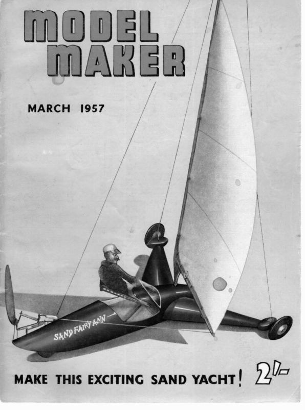
- Sand Fairy Ann.
- Radio Control Yacht Racing – A survey of the proposed M.Y.A. R/C yacht racing rules, with a report on a trial regatta, By N.D. Hatfield.
- Cirrus – A New “A” Class Yacht by S Witty.
- Trig. Class for Designers By C.H. Verity.
- Tucker’s Topical Talks – Resin Glues By H.B. Tucker

MARCH 1957 raeno MAKE THIS EXCITING SAND YACHT! pda
COPYRIGHT G SHEET — > ] ea OF v3a0 OW == \ya” WPHolland SS MODEL MAKER PLANS.SERVICE | 38, CLARENDON ALL WOOOS ARE ROD, WATFORD, BALSA UNLESS ~HERWISE HERTS. STATED rH < par fist ee N a AUTOMATIC BALLAST BALL BEARING -~? =n ADJUSTMENT SOLDERED IN TUBE : SAL FEF arrow PIT samme te ” FRONT VIEW RUBBER BAND RETURNS SEAT To © RETAINING SLEEVE FROM 16 #5. PIANO Wine | PLASTIC WIRE COVERING REAR AXLE E LEG |t t COVER BALSA SHEETING WITH LIGHT MODEL iPAN TISSUE GIVE WHOLE BODY SCOATS OF SANDING SEALER, SAND © FINISH WITH CELLULOSE OR VALSPAR . VAMMISH SPARS. es S ho 2 OFF ORILL FOR AXLE 6 BELLORANK PIVOT AXLE From iVe"Wall ———— at >) ] Sencar ‘ See Py WHEEL Yyatx Ye” SPRUCE TAPER & SAND TO STREAMLINE SECTION | —fTT _ eS Boom, Vea” UNDERSIZE FOR FORCE FIT = <= MAST => SS BRACKET ee ene ar
ie 20 tet 9 Od ae Ee airy CAN YOU RESIST THIS EASY-TO-MAKE SAND-YACHT & ITS GALLANT HELMSMAN T Hus lightheartedly christened, our latest yacht trundled down its slipway to its native habitat . . . LAND. Why worry if you live far from a suitable pond? Sand Fairy Ann will perform happily on any car park, hard court or playground, and is just the model to start a racing hobby new to the model field. Visitors to the 1956 Boat Show will recall the huge full-size craft Coronation Year Mk. II developed by Mr. R. Millett which in 1955 created a Flying Mile record at Lytham St. Annes at over 60 m.p.h.; in view of the excitement caused by the fullsize edition, it is surprising that comparatively few models have been made of land yachts. There should be no reason why model land yacht racing should not become an energetically supported sport using a vastly greater number of handy .venues. One can visualise even “A” class size models operated on aerodrome runways, possibly radio controlled and timed on a comparative efficiency method based on simultaneous readings on an air speed indicator at the trackside. There is plenty of scope for design, and whilst considerably less costly than a sailing craft of similar size, the same careful design can be put into chassis planning as is lavished on hulls, a big advantage being adjustability, even during a day’s trimming . . . just imagine a yachtsman with an elastic-sided hull! ! Seriously though, this sand yachting business is great fun, whether you “sail” for competition or not, and the little model overleaf has attracted considerable interest among the local modelling fraternity. The designer, though keeping the functional layout in mind, felt that a little embellishment in the way of a “crew” and cockpit would attract an initial sports following, with a view to starting model racing organisation capable of growing to a national following. Perhaps it would be pipe dreaming, but try these for rules: 1. Sail area similar to existing model sailing craft rules (including M.M. Class of course!) 2. Total weight of movable ballast, 2 oz./ 100 sq. in. sail. 115 \ 3. Maximum track, 4 sail peak above ground. 4. Maximum movement of movable ballast, 4 track. 5. Steering to be operated by direct action of wind on sail or vane. 6. Racing in heats of reach, beat and run, course marked out with tape or cord with bollards for markers. 7. Penalty for third touch on any one board, leg, or tack. 8. Retrim prohibited in same leg. A separate radio-controlled class could be used for speed steering events round a tortuous course on small tracks (proportional steering and sheet controls can be operated by single channel R/C). Well, now, let’s get down to building. Sand Fairy Ann is a kitchen table model, so do not be worried by the apparent technicalities. When you see it working you will realise just how simple the solutions to our problems became in this application. As for vane gear; frightening though it may be to some land lubbers, it is now reduced to its simplest and lightest possible form and needs only a pair of pliers and a dab or two of solder to pro-
a, . @ Bikey: “ay ‘ ai FiO DEL MAKER) duce a self tacker to keep your model “on the rails.” Start by cutting the chassis parts from } in. ply. Durofix together and add 4 in. balsa formers for body and front outriggers. Make the front axle blocks from 3 in. beech or oak, Durofix to outriggers and drill to take stub axles (unshamedly 14 in. nails!). Slot and drill for bellcranks and file to streamline shape. By now the formers should be ready for covering. Note that the outriggers are covered first, followed by adding the top parts of Fl and F2. The mast step is made from a 4 B.A. bolt and nut, a piece of brass tube being soldered to the end of the bolt after running on the nut. A strip of brass or tinplate is soldered to the nut as additional support, and the whole unit is glued to the chassis, tube uppermost. Complete the 1/16 in. body sheeting and add tail block. Drill chassis for rear steering tube (force fit) and bent 16 s.w.g. piano wire rear axle to form a safety pin type spring, finally bringing it through the tube and bending down as reversed tiller. Secure the rear wheel with a scrap of plastic sleeving from wire covering. Rubber-tyred wheels are a “must.” Streamlined sponge rubber of the type sold for model aircraft are shown, 2 in. front and 14 in. rear. In order that weather may not hold up operations, a set of skis are illustrated as an accessory. The swinging seat is cut from 18 s.w.g. aluminium and bent to shape, and 6 B.A. bolts and nuts from a pivot. Two bellcranks are also cut from the aluminium and pivoted on panel pins in the axle blocks. Choose a straight-grained piece of pine for the mast and boom, 3/16 in. x 2 in. Cut the 3/16 in. ply mast foot bracket and Durofix mast and boom in place, forming a rigid unit Close-up of the ultra-simple Vane Gear. It may horrify the more experienced model yachtsmen, but there is enough in it to keep Sand Fairy Ann going where she ought! almost like a wingsail. Drill the bottom of the bracket for a further 14 in. nail (less head), the purpose of which is to pivot in the mast step tube. A panel pin is fixed in similar manner at the mast top, and pivots in a scrap of tube or perspex block. The three shrouds are attached to this latter unit, the rear running to a screw hook forward of the steering tube, the others to the bellcranks and thence to the seat, so that excess wind pressure acting sideways on the sail moves the mast slightly and pulls the seat out on the weather side by an amount proportionate to the wind strength. A rubber band returns everything to the original position. So there is your movable ballast mechanism, simple, isn’t it? A plasticine crew provides the necessary weight, aft for running and to weather on reach or beat. Complete the model with several coats of sanding sealer then cellulose or Valspar to desired colour. The rather unorthodox rig warrants a word on sail making. You will note that the jackline is run in the hem of the sail, not on the spars. This is the result of the desire to clean up on mast turbulence, and is a method used successfully on a number of the author’s sailing craft. Cut the sail with selvedge parallel to the leach or rear edge of sail, use polystrene cement or Durofix for all hems. ‘Battens are 22 s.w.g. piano wire and are secured with a strip of silk cemented on place over the wire. 22 s.w.g. piano wire hooks are fitted through holes in the mast and boom and secure the jackline where it protrudes through the cutouts in the hems. The ends of the jackline pass over further hooks and return to sail peak and clew via bowsies, The sheet bowsie should be of the non-slip type. The vane gear should be self-explanatory from the plan, but a little extra gen may be useful. The tube bearings contain a ball bearing or lead shot forced in place. Be careful to file or grind the ends of the wire smooth to bear on the shot. Wind the tiller link on a piece of 18 s.w.g. wire if difficulty is experienced in obtaining a sufficiently tight grip on the tee post. To trim for closer tack slide the stop forward on the vane yoke. The running lock drops over both vane arm and yoke. The newcomer to vane gear will find this little unit simple to operate, and being on terra firma, a close inspection can be made whilst in action.
MARCH, RADIO 1957 CONTROL YACHT RACING A survey of racing rules, the proposed M.Y.A. with a report on a R/C yacht trial regatta, by N. D. Hatfield. Comments on this subject are invited, and an analysis of opinions will be published in a future issue. EPRESENTATIVES of the M.Y.A. who were present on the MopEL MAKER Stand at the 1956 National Boat Show found many visitors who were interested in the problems of Radio Control for Model Yachting, and took the opportunity of discussing with them the many ideas put forward concerning classes of model and rules to govern racing. The M.Y.A. Council decided, during 1956, to publish suggestions to form a basis for a set of rules to enable radio enthusiasts to plan their future experiments on organised lines. Unfortunately, however, the long absence of The M.Y.A. News has delayed the appearance of these suggestions until now. The Council therefore invites comment on them, and if they appear sound, it is the intention to set up a sub-committee to draft a set of rules to govern classes and racing. Suggestions for the Formation of a Set of Rules for Radio-Controlled Model Yacht Racing 1, There should be two classes of model, namely:— Class 1—Models equipped with -radio control of sheets and helm, including radio control of the vane, and other systems other than in Class II. Class 1i—Models equipped with radio control of helm, but fitted with automatic sheeting systems. 2. Models equipped with Class I control shall conform to the 10-Rater Rules, and models with Class II control to the Marblehead Rule. The measurement rules shall apply only in general terms to the hull and sail area, with minor restrictions of the existing rules deleted for simplicity. 3. The course to be sailed shall be either triangular or quadrilateral, marked by buoys with flags. No buoy shall be placed nearer than 15 feet to any shore, and no leg of a course shall be shorter than 40 feet. 4. The number of yachts taking part in any one heat shall be determined by the number able to sail without mutual radio interference. Class II models using single-channel constant-wave radio shall employ crystal-controlled equipment for racing to minimise the chance of interference. In the event of two finalists suffering from mutual interference, each model shall make a timed circuit, the order of sailing being determined by the toss of a coin, and the second model starting within five minutes of the first crossing the finishing line. 5. Transmitters shall be stationary midway along one shore of the lake, and all transmitters shall be impounded 15 minutes before the start of Heading shows George Honnest-Redlich, a pioneer in this as in other branches of R/C, with his 36 in. “Lancet”. Right: An A boat and a 10-rater jockey for position while awaiting the starter’s whistle 117 the race. Testing before this time shall be by arrangement between competitors. -A model shall be started by the skipper’s mate, who will follow the model’s course, and who will be permitted to pole her off should she touch the shore, but will not be allowed to make any adjustments to sails, helm, or control equipment. . Sailing rules’ shall be based on the R.Y.A. Rules, the establishment of overlap, etc., being judged by Umpires stationed opposite the mark buoys. A system of hand signals shall be devised between skipper and mate for indication of appropriate positions for going about, etc. (It is intended that the draft rules will include those
for stants in which any compete at the same time. number of boats may Eleven entries were received from the following Clubs: — Bristol, Poole, Gosport, and the Y.M.6-m.0.A., and the fleet consisted of five “A” Class, two 10-Raters, and four Marbleheads. The Regatta was favoured with a day of brilliant sunshine, but the wind was light and _ variable. However, a triangular course was marked out with buoys, two long legs of which gave a reach, and a short leg to windward, involving a tricky turn at the weather mark. Each boat in the fleet sailed a timed circuit in turn, only two boats failing to control properly, and this event was won easily by Mr. G. Honnest-Redlich with his “A” Class. In the afternoon, it was found possible to start five boats at the same time without interference, and these five, which consisted of two “A” Class, a 10-Rater, and two Marbleheads, completed one circuit successfully, the winner being Mr. A. T. Tamplin’s “A” Class Kit. Summing up, it may be said that:— 1.The winners of both events had excellent control over their boats, and in the race, Mr. Tamplins control was particularly impressive, his gear being efficient, although doubtless very expensive. It is essential to have effective control over both helm and sheets, otherwise, of course, the boat is never sailing properly. 2.There was not time to devise a fair system of handicapping, and all boats started from scratch. However, the Rules provide for this if required. sections of the R.Y.A. Rules which apply, and that other sections of the Rules which are not included shall be ignored.) 8. The O.0.D. shall have discretion to alter buoy positions to suit weather and other conditions. As a sequence to the above, the Y.M.6-m.0O.A. staged a Radio Control Regatta at the Rick Pond, on Sunday, for Model Yachts 14th October, 1956, the main object of which was to determine what progress has been made with regard to the efficiency of control over helm and sheets, and to give members the opportunity to assess for themselves the appeal of sailing a model by radio control. In addition, a set of Sailing Rules was drawn up by the Club to govern competition by different classes on a handicap basis over a timed circuit. These Rules, which are given below, are on familiar R.Y.A. lines, and provide 3. As far as could be judged in the time available, the Rules worked well, and were understood by the competitors. 4.No collisions occurred at any time during the Regatta. 5. The competitors enjoyed the day, and expressed appreciation to the Club for having staged the event. The following are a few examples of the views and objections to Radio Control raised by some members on the grounds that:— a. It is expensive. b. It requires sound technical knowledge of electronics, combined with practical application and (Continued on page 152) Top left: J. C. Hogg, another radio yacht pioneer, thinks outa problem with his Marblehead, seen (/e/t) threading her way delicately through flags and buoys. Above are the visible “works” of an A boat sailed by Col. C. E. Bowden, yet another trail-blazer 118
MODEL MAKER A Cixwus WE We ope: Gino. YACHT BY N commencing the design of an “A” class yacht the first and probably the most important decision to be made is on the amount of beam to be incorporated. Once made the general type of hull is fixed more or less automatically since the W.L. length dimension seems to have become stabilized at around 54in. It is obvious that designs cannot go on increasing in length indefinitely and those who try to continue the trend past a certain margin must inevitably be doomed to disappointment at least in light weather performance. run or weakening the lateral stability. However, DIMENSIONS cl RRUS LENGTH OA Das oNeP BY MODEL MAKER PLANS SERVICE 38. CLARENDON FR De WATFORD. wens 81:0 Hippotas 540 144 By No. ar aR wm VB © 54x 39-5 B.H. Priest MM/263 12/6 MM/247 12/6 80:0 544 13:5 562 J. A. Lewis Windflower78-4 56:0 143 57-2 H.B. Tucker MM/320 15/- Saxon 55:0 146 565 B.H. Priest 81:0 1° 12″ Be One SAIL AREA yas! 560 SOS OBL 50-85″ Sor ph 2 fe S136″ ‘SAILPLAN MAX 64° HT FORE A ANO MAX 6a” ACTUAL 4 22 aw ALLOWED MIN. FREEBOARD ALLOWED ACTUAL: © ihiee” ae DISPLACEMENT TRIMMING 5 4 3 r\] ‘ae welt I MM/462 15/- 130 0 Biss se Ts aoe UAL VNB ale N wus wus \ \ MAN A IIS ISIE | hI SS “ 2 wee TTT e) 4:16 Av 40 LBs BALLAST SECTIONS SPACED 2 65 53 LBs. LEAD Price 560 54″ MAX ALLOWED 54439 so BEAM MAX DRAUGHT HT R» we PN wWL7 L.O.A.L.W.L. Beam Weight ETC LENGTH LL S.Witty CoPrmrcHT oF Full-size copies of this reduced scale plan can be obtained price 12/6 post free from Model Maker Plans Service, 38 Clarendon Road, Watford, Herts. These plans give full-size body plan and keel lines with half-size sheer and waterlines, and reduced sail plan. Other “fA” designs available in plan form include: Saracen Wily than under it. Obviously it will flow more easily around a narrow hull than around one of greater beam. While “A” class designs of small beam have an advantage in most conditions, their consistency being due to a high average rather than a high maximum speed, it is difficult to know just how much the beam can be reduced without certain disadvantages arising such as a tendency to roll when on the In the design shown the beam does not exceed 14 in. since narrow deepish sections can accommodate a large displacement with much less apparent bulk than do those of greater beam. This fact is of great importance because the design of these heavy displacement types is veritably a “battle of the bulge”. The main advantage usually associated with this kind of hull is that of low wetted area but actually in comparison with the total wetted area for a design with a beam of around 154 in., the difference is quite small; not enough to account for the general superiority of this type. Narrow yachts show to their best advantage in light weather since as wave formation is negligible for either type of hull under these conditions the water remains in laminae or in other words must flow around the hull rather 3. A ie | TT | < yA 7 Lj i an ei ° y ry 3 be ~
1957 MARCH, which allows for cleaning up of the casting. Both skeg and rudder are of normal type, except that a in. dia. rudder post is usea, since the usual } in post is too small to provide a reasonably strong streamline section without (as is too often seen) either a definite break in the surface or with skeg and rudder forming after drawing no less than five complete designs of this type with beam ranging from 124 in. upwards I have reached the conclusion that 14 in. is the best minimum beam for all round performance. Also below this figure an appreciable amount of twist becomes apparent in the planking of the hull. The dynamic balance has been carefully considered and since the maximum hull depth falls just aft of the mid-section the fin root is also centred around this point and will fit snugly into the wave hollow when heeled. Too many yachts seem to progress to windward in a series of shallow arcs, where not only the speed and angle of attack of both fin and sailplan vary, but also the angle of heel. That is not to say a yacht should not point a little higher in a squall to ease her sail, but in most cases this tendency is overdone. The fin has been drawn to avoid the blunt-nosed type of section without decreasing the chord-thickness ratio too much. Even so, the fin and fairing together have a displacement in excess of 8 Ibs. which helps considerably towards the total. The lead has been calculated to weigh approx. 41 lbs. taking the mass at .39 Ibs. per cu. in., an x: 3 a = 4 = = Lwe 5 6 NX z ef] Fy a peculiar sort of hour glass section. The sailplan is very average both in style and size for this class of yacht, and has been kept well within the rating figures since I consider that to present a design at the max. rating figure of 39.37in. is hardly advisable, since a few weeks sailing will stretch the sails out of rating. Enough deck clearance has been allowed, so that a fair length of kicking strap can be incorporated although the performance might be further improved by allowing for an even greater length of strap. After all, it is pointless to have a large sail area unless it can be kept flat and at approximately the same angle of incidence the whole way up. In this connection it is interesting to note that the “A” class “Ranger” had a mainsail deck clearance of 63in. which may well have had something to do with her excellent performance. 0 " \ae ay a (age So Te ae } 6 [dae ar ee 7 eet a a a S Saat a ee \ eee IAS ma os Sue ena oN ay Ne Sa eee Se ee fh ee Nar eles. A ‘* a NS Se) 1% i == ~G Seehil See eg 2 = rea a N ers +> ESS \ \ Sra SN AN A| ——_ 1 Eee —————— a ww? cS ase a! LEAD LINE (iin } ©B LEAD 40 Les. anki ae EMENT CURVES UPRIGHT AND HELD ZO* Se 131 = Pot eel a —— SN AS ea Se SaEE ZA —
MODEL MAKER) Fig TRIG. ° Y > WH) | ! Zz | Wi. W =Weight of Body in Ibs. G =C.G. B, =Centre of Buoyancy of Displaced Liquid sie of Bod to B =W M =Metacentre Triangle of Forces of of = Metacentre =Force acting throughC.L.R. as Sil Rs ITH reference to Mr. Tucker’s ‘Topical Talk’ in the current issue of MopEL MAKER and Mr. Stainsby’s chase of x I would like to offer the following comments as Mr. Tucker seems to have some rather peculiar doubts. degrees, a third force must be applied in such a position to cause the “heel” Fig. 1, then for equilibrium in a vertical direction W+W,=B, 1 Producing the lines of action of the forces the point “M” where “B,” cuts the centre line of the body is the metacentre about which the body rotates or “rolls” under that particular system of forces, and for equilibrium we have find the closed triangle of forces. finite force, but we know common arm G.M. sin @) acting in a direction we use the centre of effort and equate the righting moment to the “assumed” heeling moment which A body floating upright in a state of equilibrium equal magnitude but acting in opposite directions, therefore if W=weight and B the buoyancy then W=B. To give the body an angular displacement, say @ and WxG.M. sin 9 =RxL.N. cos @ 4 Regarding the wind force F and Q we are assuming that the sails are fixed in a fore and aft direction with the wind on the beam and square on to the sails, which assumption does not occur when sailing. Formula 3 therefore can only be useful in comparing sail plans for similar classes and it is useless to try and find wind velocity by this method, or even the wind pressure when sailing. We know the position at which R acts, but the position of Q would be very difficult to find, and as R is a finite force with a definite position, and further that we are only taking sail area into account, etc. has two forces acting upon it (a) the weight of the body acting vertically downwards and (b) the upward thrust of the displaced liquid, and both of try anti-clockwise, and R and Q (with a common arm L.N. cos @) acting in a clockwise direction and these two couples will balance =Total Force of Wind acting on Sails, Hull, =Centre Effort to Referring to Fig.3 let R be the force or reaction of the water acting through the C.L.R. and Q the force of the wind, which in addition to acting on the sails also acts on the exposed surface of the hull and on the rigging etc., it therefore ‘cannot act at the centre of effort but at some point between M and E, say point N. For equilibrium of the forces in a_ horizontal direction R=Q and we now have the two couples referred to by Mr. Stainsby viz.: W and B (with GME=Centre Line of Mast when Heeled Q moments to the force of the wind. a =o these there is a force acting through the C.L.R. (due to the resistance of the water) in the opposite direction =Effective Arm of Force W =Centre ffort of centre” we cannot apply a MO=Effective Arm of Force F E one As “M” is a point in space or an “instantaneous =Total Force (in Ibs.) of Sails MY use system F.W. and K form a G»=CG, ‘of. Yacht F W x Y.M.=W, x Z.M. or WxG.M. sin o =W,xG.M. cos @ ve Now applied to a model yacht, Mr. Tucker wishes or effort, and discarding force W, in Fig.l, the equation will be WxG.M. sin 9 =Fx M.E. cos a. 3 and not F times the “distance moved”. This system of forces is, however, not balanced about M and to complete the balance a third force “K” must be applied (as shown dotted), so that the W =Weight | of Yacht in Ibs, w DESIGNERS “wind pressure” on the sails, so referring to Fig.2 let us say it is force F acting at the centre of pressure W, =Weight causing Heel in Ibs. Ww FOR CONDUCTED BY VETERAN MODEL YACHTSMAN C. H. VERITY, SNR. | /M em CLASS will be WxG.M. sin 6 =FxM.E. cos o Mr. Tucker will no doubt observe that the heeling moment is not Fx the distance moved by E. The above forces are all static and are assumed to lie in the same vertical plane. When sailing the reaction R would tend to increase slightly due to any leeward movement and Q would thereby be slightly reduced, but the velocity of the yacht to leeward is so small that any change in pressures due to the “change in velocity” could be neglected. May I point out that Mr. Tucker’s figure of P=0.186in. oz. on page 48 should be P=0.0186 in. oz. which will give him a much less wind velocity. 146
MODEL MAKER! YACHT RADIO CONTROL (continued from page 118) (iii) A boat sailing with the wind free (i.e., running or reaching) must keep clear of a boat sailing close-hauled. (iv) When two boats encounter each other on opposite tacks, the boat on the port tack (i.e., with the wind on her port side) must give ability as a skipper if one is to be successful. c. It is impossible to control efficiently at a distance without the assistance of a mate with binoculars, who must give quick commands for alterations way to the boat on the starboard tack (i.e., with the wind on her starboard side). of course. d.It is necessary for the skipper to remain stationary at his control, and therefore he does not derive benefit from exercise by walking or running to keep up with his boat: On a cold, windy day, this can be a disadvantage, unless (v) When two boats are sailing together on the same tack, the windward boat must keep clear of the leeward boat. (If either boat is ahead of the other, Rule (vi) applies.) (vi) When one boat is in a position from which she might overtake another on a similar course, the overtaking boat must keep clear. (When the overtaking boat has drawn level with her some shelter is available. e.It is difficult, if not impossible, to operate in wet weather without adequate cover and protecThis difficulty is further aggravated in tion. heavy weather unless the equipment is perfectly opponent, she cases to be “overtaking boat” and Rule (v) applies. If she then draws ahead, ne a“ left astern becomes the overtaking sealed. f. Spinnakers cannot be used, and therefore speed down wind is reduced, with consequent loss of oat. (vii) A boat may not tack so as to involve a collision with another boat unless she can gather proper way on her new tack before a collision would the ability to plane. g. Timed circuits round buoys, sailed by one boat at a time, is apt to become boring for those not taking part, and it is necessary for two or more boats to be able to race together without occur. (viii) When a boat approaching the shore is prevented by the proximity of another boat from manoeuvring freely to avoid running aground, her skipper may call “water.” The offshore boat must immediately be manoeuvred so as to allow the inshore boat room to come about, or otherwise draw clear of the shoal water. A call of “water” places on the skipper who calls, the obligation to manoeuvre his boat clear of the shore immediately he has room to do so. He may not put his opponent at a disadvantage by causing him to alter the course of his boat in response to a call of “water” when his own boat does not need immediately to perform a similar manoeuvre. (ix) When two boats are approaching a mark together, the boat in the outside position shall not be manoeuvred so as to force the boat in interference. It is hoped that the above observations and the following Rules will be of interest and assistance to those who are really keen on this branch of the sport, and further comments and suggestions from readers will be considered by the M.Y.A. Council. System of Racing Racing will be conducted by starting boats in pairs, of similar Class so far as this is possible. Each boat will be timed over the course set, prizes being awarded in order of sailing time, adjusted by allowances and penalties as appropriate. Time allowances follows:— will be made according to Class, as @ 1. Sve 3on ae Rete Btn A Scratch.* FA the inside position to pass the mark on the wrong hand. A skipper who sees his boat being so impeded may call “water.” The outside boat must immediately be manoeuvred so as to allow the inside boat free passage round the mark. (If a boat is approaching a mark close astern of another. boat, her skipper may not call “water,” but must keep his boat clear in accordance with Rule (vi). (x) A boat which has run aground may be re-floated by moving her sideways or astern until she is clear of the bottom. She must then be left to gather way of her own accord. On no account may a boat be moved ahead or have way imparted to her in the course of being re-floated. 10-Rater Class ………… ? seconds. M-Class esha Naas, ? seconds. tess ? seconds. 3 Gains! (OlASS i eta Competitors will be called by the Starter to launch their boats as required. When both boats are afloat and under control, the Starter will blow two short blasts on a whistle as a warning to the skippers Two minutes after the to get ready to start. warning whistle, one short blast on the whistle will denote the start of the race, and timing will Competitors should endeavour to cross the begin. starting line as soon as possible after the warning whistle. Any boat which is across the line at the starting whistle will be recalled by the Starter, and must return and re-cross the line. In doing so, a recalled boat must keep out of the way of all other boats which are starting, or have started correctly. Each infringement of the above Rules will incur a time penalty of 10 seconds. (This time penalty appears inadequate for some infringements and might invite a deliberate acceptance of penalty rather than comply with rule—Epb.). If two boats collide as a result of an infringement of a Rule, but are not entangled, they may continue to race, the offending boat being subject to penalty as above. If the boats. collide and become entangled, so that they are appre- Sailing Rules (i) Boats must not collide with course marks. (ii) Boats must pass course marks on the hand stated on the course card. A mark passed on the wrong hand must be re-passed on the Re-passing a mark does not correct hand. incur an additional time penalty. ciably delayed, the race shall *Fixed handicaps cannot be given due to varying waters, but for the Rick Pond, for windward and return (1,700 ft. total), reasonable be re-sailed. The penalty incurred by the offending boat on account of figures would appear to be: A—scratch, 10-R.— 30 secs.. M— 45 secs., 36-R—60 secs. 152 the “Sail: shall be added to her time for the re-sail.
MARCH, i use of resin glues in boat-building is now almost universal, and this coupled with the scarcity of good timber has led to many changes in design and methods of construction. Resin glues (or more properly cements) were primarily a German discovery, but British scientists were also working on this problem about 1938-1939. Nevertheless, these adhesives were in a more or less embryo stage of development when the war started, and casein glues were employed in making many types of military aeroplanes. Due to the high accident rate caused by structural failures, searching investigations were made, and it was found that casein-glued joints deteriorated at an alarming rate when exposed to weather and damp. Research into resin adhesives was pressed on with, and as a result, it was possible to build the revolutionary Mosquito planes, which for a time dominated the skies. Resin glues also played their part in building the M.T.B.’s and other light craft. When after the war, yacht and _ boat-builders enquired from the resin-glue makers about the likely life of craft built with these new adhesives, they were told that as the cements had only been in existence a year or two, no guarantee could be given. Sufficient time has now elapsed, however, and much has been learnt in the meantime. Resin glues are often spoken of as being ‘waterproof,’ but they are not waterproof in the sense that an oilskin is waterproof. They are waterresistant, in that they do not dissolve or lose adhesion when wet. These cements consist of two parts, the resin and the hardener. The resins are of two kinds, the P.F. (Phenol- Formaldehyde) and U.F. (UreaFormaldehyde), but to-day most are U.F. The resin is a thick, treacly compound of varying viscosity. The hardeners (sometimes called ‘catalysts,’ or ‘accelerators’) are liquid acid compounds. Until the hardener comes into contact with the resin, the glue will not set, hence the names of ‘hardener’ or ‘catalyst’. By varying the composition of the hardener, rates of setting can be retarded or accelerated, which accounts for the alternative name. Resin cements can be either ‘hot-setting’ or ‘coldsetting’, but the former require special muffles {or ovens), heated presses, jigs, etc., and are only suitable for factory use on mass-produced jobs, so are of no use to the average yacht-builder or model-maker, and need not be dealt with here. In passing, it may be mentioned that plywood is invariably made with hot-setting glue, as is mentioned later in this article. There are two methods of using these coldsetting cements. The first is the ‘mixed’ application method and the second the ‘separate’ application method. In the first, the resin and hardener are mixed together, and the mixture applied to the surfaces to be joined. In the second, the resin is applied to one face of the joint and the hardener to the other. In model yacht building, one method suits some jobs, and the other suits other jobs best. The resins can be either ready-mixed or in powder form. The disadvantage of ready-mixed resins from the model-maker’s point of view is mainly their short ‘shelf life’. By ‘shelf life,’ is meant the time that the resin will keep before it becomes stringy and starts to ‘gel’. From time of manufacture to use, with most makes this does not exceed six months, and as the quantities sold in tins are usually on the large side for model-makers, the 153 fa 1957 UCKER’S TOPICAL MAINLY ON THE USE OF TALKS RESIN GLUES Ns a y, desiccated powder form may be preferred. The above shelf-life assumes the resin is kept in an airtight tin in a cool place. The powder form has an indefinite shelf life until it is made up by mixing. with water, after which it has the same shelf life as ready-made resin provided it is properly kept in an air-tight tin. The hardener has an_ indefinite shelf-life. It should be added that resin should be thrown away once it starts to gel, as it will not make a good joint. One further advantage of the powder form is that it enables the worker to vary the thickness (or viscosity) of the resin, and enables him to use a thinner resin when the surfaces are good and make good contact, thus getting a thinner glue-line, or a thicker resin whén ‘gap-filling’ properties are wanted. Actually, glue-lines can be anything up to 1/20th-in. thick without prejudice to the strength of the joint, provided a ‘gap-filling’ cement is used. Since all resin glues are not gap-filling, the worker should inform himself on this point: beforehand. The term ‘pot-life’ is used to imply the maximum length of time that resin remains usable after it is taken out of the air-tight tin until it is spread. In the mixed (or combined) application method, it starts when the resin and hardener are mixed. The time taken in lining up and assembling the joint is known either as the ‘assembly-time’ or more colloquially ‘shuffling-time,’ and is the maximum time that is permissible between actual contact of the surfaces and the application of pressure (or cramping up). The time that can be allowed for this is directly in relation to the pot-life and pressing-time. The shorter the pressing-time, the shorter the assembly-time. Tables of these various times at different temperatures are furnished by the various makers for these cements. ‘Pressing-time’ is, of course, the length of time the joint must be kept under pressure, but actually it takes considerably longer before the joint develops its full strength. In any case the maker’s instructions must be carefully studied and followed implicitly. In full-sized yacht and boat work, more and more Sharpies are being built as this permits the use of plywoods and cheaper timbers. As _ previously mentioned, plywood is bonded by the hot-setting process. It is not certain whether it is the effect of the hot pressing or of the acid content of the hardeners, but plywood is often water-repellant, or in other words, water will not soak into it. Often it can be seen that the surface has become glazed, What has happened is that the pores in the cellulose fibres of the timber have been closed over. Glue bonds the two surfaces of a joint by keying into these little pores, and glazing prevents the glue penetrating. In consequence a weak joint ensues. The cure is to glass-paper the plywood in the way of the joint. Hardwoods should be roughened slightly. Sawn surfaces can be glued together, but in such a case, the glue should be applied to both faces of the joint to benefit by its gap-filling quality.
MODEL MAKER One important point to remember is that the separate application method is unsatisfactory when a thick glue-line is used for gap-filling purposes. The reason is apparently that the hardener fails to penetrate right through the resin, which results in good adhesion to one face of the joint only. is nipped off, the chisel point thus created will be found to penetrate very well indeed. Another thing which is sometimes found in boats that have been in existence some years is that while the majority of the joints stay good, here and there may be an occasional joint failure. I took the opportunity recently to ask one of the technical staff of a well-known maker of resin glues how this could come about. He told me that when a number of layers (or laminations) of fairly thick wood are glued up, as in a bread-and-butter hull, and exposed to moisture, swelling occurs, and as they dry out again, they shrink back to more or less their original thickness. Most resin glues a few years back set rock hard without any elasticity whatsoever. The swelling and shrinkage then became cumulative over a number of lamina, harder and stronger full strain fell on the spot in the cellulose and since the glue lines were than the wooden layers, the wood, finding out the weakest tissue. Then possibly a split would occur in this weak layer, and more probably the wood would become fatigued. It was mentioned above that glue bonds the two faces of a joint by keying into the surface pores. In other words, the glue has tiny ‘projections anchored into the pores of the wood. When the wood becomes fatigued, the pores become enlarged and the anchors lose their grip, with the result the glue comes away from the wood and the joint is broken. When this was discovered, the resin cement makers realised that the only manner of preventing this is to make the glue slightly elastic by the admixture of certain plastic materials. Then when the wood swells, the glue is compressed, and when it shrinks again, the glue expands to suit the joint. A good example of a resin glue that has this plastic quality is Beetle A2, which can be had either in powder or resin form, and used by either the separate application or mixed application methods. By now, our winter work should be well advanced. overhauls and alterations almost finished, and new constructions nearing completion. Now, however well designed, built and equipped, boats require careful tuning up before serious racing commences, and even the most expert skipper has to know his craft before he gets the best out of her. Far too often in the past, boats have sailed in Championships and other important races with insufficient preparation, and in consequence have not acquitted themselves as they should have. This is particularly so when the yacht is to an entirely new design, as in the sister of an existing craft, many teething troubles have already been ironed out. Hence, it is important to get new designs into the water as early as possible to try them out under varying conditions of wind and weather. It is, however, pure waste of time to practice with a new or altered yacht until she has been properly measured, and one is certain she is on her correct fore-and-aft trim and L.W.L. length. Competition is so keen nowadays that the designer can afford to throw nothing away, and must go right to the limit in his sail area. In consequence, it is not a bad idea to get the measurer to check the hull measurements with an old suit of sails set, before having the first suit made for a new boat. Otherwise, a very slight difference in hull measurements may possibly entail a small reduction in S.A. a baer an alteration to a brand new suit of sails. Designers are always pleased to hear reports of boats to their lines. This is specially so with published designs, as otherwise they have no knowledge of where these are built, or how they perform. It is impossible to visit every sailing water and regatta in the U.K., so designers depend largely on reports from owners and others. I may also add that an adverse report can be as informative as a favourable one, even if less gratifying! May Finally, here is a little tip for users of plywood, which has nothing to do with glue. Frequently, the plywood is extremely tough, and it is almost impossible to drive the little copper or brass tacks, used for securing the skin to the frames, etc., clean through it. If the tip fashioned on the nail I add to the above, a plea to compilers of regatta reports during the ensuing season always to include the name of the designer and of the design of leading boats. Not only is this fair to the designer, but assists his work, as well as being an added inducement. In the case of a published design, it is also an assistance to model builders wanting a design to build to.


