- China Boy – Hard-Chine Marblehead for Radio Control
- Designed for simplicity and affordability
- Single-chine sharpie hull for easy construction and good light-weather performance.
- Low center of gravity achieved by positioning radio gear forward to balance lead keel.
- Fin and lead bulb designed for metacentric and dynamic balance.
- Light scantlings, simple tools, and readily available materials.
- Alternative fin design provided for free-sailing version.
- Moderate aspect ratio with large jib for efficiency and ease of handling.
- A-Class Rating Rule Discussion
- Rule introduced in 1923; early designs were tentative.
- Modern yachts differ greatly from early ones in size and displacement.
- Debate between lightweight vs. heavyweight designs under the same formula.
- Heavyweight yachts with L.W.L. around 55–56 in. and displacement near 65 lb. offer best all-round performance.

Cossa ck
MODEL MAKER Problems of Radio Control HE development of the radio controlled yacht is still very much in the experimental stage, but the growing interest in this field of experiment is sure to result in considerable progress being made during the next few years. The lines on which this progress will be made are not yet CHINA BO clearly This top-class hard chine Marblehe defined; there is still room for a great deal of collaboration between those expert in the particular design, ideal for either radio control art and science of yacht sailing, and those with free-sailing, is one of the most eagerly: the necessary technical knowledge in the radio field. As a radio engineer by profession, I can appreciate these problems from both points of view, but I the rudder is not to steer the boat. The course am none the less convinced that the effective radio on which it is to sail is determined by the trim control of a yacht can provide a great measure © of the sails. The only function of the rudder is of satisfaction peculiarly its own. Certainly a to provide the small amount of weather helm craft of this nature would be a much safer thing needed to hold the yacht on the course for to handle than either a fast power boat or an which it is trimmed, and by small variations in aircraft, all too many of which come to an the amount of helm, correct any tendencies to untimely and expensive end as a result of. a fault deviate, resulting from changes in wind pressure. in the system or an error in handling. This helm correction has to be applied instantly Those who are not experienced in handling a Full-size copies of the reduced plan below, yacht do not always appreciate that the purpose of post free from Model Maker Plans S oS PR PFFS LESS SSDS SSS CHINA BOY DESIGNED BY DA.Macdonald COPYRIGHT OF MODEL MAKER 38, PLANS CLAREWOON RO, SERVICE WATFORD, HERTS TM PLATFORMS FOR ae? —— aes 5 —t SS Buoces LocaTe Posts On (a3 3. 4 aj BUILDING BOARD U CARLING ad \ @ OF DECK BEAMS Post Se > x == Ae CARLINGS FOR MAIN HATCH re B HORSE OR ZE! A Pad CHINE STRAKE =e post ae oi. AZ af FA NOTE POSITION OF MOULDS a TY Loe. os. CARLING “ ai ee Loe. PLATFORM FOR RECEIVER AND BATTERIES ~ , Fr z[<|- oP TYPICAL VIEW OF CHINE STRAKE BUILDING BOARD LINE T 1 Tl} ' t ' |ha lr 2 > OPTIONAL _—— \ % FAIRING 26 CHINE LINE te POSTS & THIS PART OF KEELSON ‘CENTRE CUTAS PART OF FIN 3 SSS
JANUARY, here an autopilot is needed, to hold the aircraft on the desired course, a change of course being transJI am mitted as information to the autopilot. a / awaited plans we have ever published. convinced that this system of control is essential A vane gear would provide the for a yacht. autopilot action and ensure that the-boat sailed desired course, responding the on effectively Expert skipper and designer D. A. Macdonald discusses the design in this article; in parts two and three he will provide step-by-step correctly and instantly to changes in wind force and direction. The course to be set would then be controlled by radio equipment operating the for guidance construction and tuning sheets and setting the vane angle. and to exactly the right amount, as the wind pressure varies. On a manned yacht, the helmsman does this instinctively, and with an accuracy born of skill and experience. He could not do it by remote control any more effectively than he could steer a motor car from a distance over a winding road varying constantly in camber, and full of potholes! Similar problems apply to the control of aircraft over appreciable distances, and M 501, are available by return post, price 10s. 6d. ice, 38 Clarendon Road, Watford, Herts. CAMBER CONSTANT ON ALL BEANS ‘DATA ; sire LOA TYPICAL DECK BEAM hs ae BEAM; DRAFT °: : Designing for Radio Control Fortunately it is not my present task to devise a radio control system. My purpose is to design a yacht of very simple construction, to enable radio control enthusiasts to embark on experiments in this field. To keep the work simple and the cost low, a small class yacht has been selected, the M-class being about the smallest that could carry a fairly comprehensive set of equipment, and at the same time prove docile and easy to handle under all normal weather conditions. A simple solution might be thought 49-4″ | at ed ME 16°75Lobs. ZZ z ee nr ‘SECK LAID ON TOP OF THIS LINE a4 LE td 3 = Al | STRINGER She ot fe oe ob S Bes oe as ArT \ Wi INWALE Vit \ pie ————— Saas 6 ® STERN ‘BLOCK STERN TRANSOM(T2) WATER Way CROSS SECTION SHOWING inherent stability, but such a craft would generally not prove docile under automatic control, owing to the severe change of form when heeled. Constructional problems aside, the ideal hull form might well be a circular are type with end corrections to offset the steering effect of the fin, and, in fact, the preliminary “doodles” for a craft of this kind are beginning to appear round my drawing board. But we are here concerned with a yacht of the simplest possible kind, consistent with good performance, and the ultimate selection is therefore a single chine sharpie of moderately light displacement and super-simple construction. A modest initial stability is to be coupled with a low centre of gravity, the latter to be achieved, desnite the weight of equipment carried, by a design trick to – be explained later. KEEL POST & FLOOR The Design To produce this design, an existing boat (produced a few years ago as a simple yacht for juniors) was taken as a basis, and all improvements which had proved desirable in the light of experiences with the original were incorporated. 7 FLOOR LIGHTENING HOLES KEEL POST 0 DECK BEAM be a displacement would be a sluggish and_ inefficient craft, and the only compromise between this poor performance and more difficult construction would be a multi-chine sharpie, offering little advantage either way. A _ low-displacement craft, by reason of the small stresses involved, can be of very light and simple construction, the only real problem being that of achieving a low’centre of gravity when loaded with the radio control gear. Admittedly a high centre of gravity might be tolerated if the hull were designed for a_ high KEELSON A ; to heavy displacement craft, the performance of which would not be much affected by the addition of the control equipment above ‘the L.W.L. (and the corresponding reduction of lead in the keel). This solution would be a simple one for the designer, but the builder would have to bear the greater cost resulting from the increased quantity of materials involved in the larger and heavier structure. A simple type of sharpie with a high SOY 8 DISPLACEMENT: a 1958 The finalised prototype, in its vane-steered version, has proved an efficient performer. In its first open LOCATING trophy race, skippered by place, against experienced 27 a junior, it gained first opposition, and it has
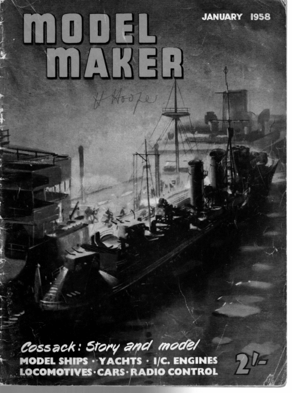
yh mx | SOOO OOOO: OF WEIGHT RX & BATTERIES Fin and Lead & San MODE MAKER 0.6. OF CONTROL GEAR WEIGHT OF SHEET ACTUATOR IGHT OF a GEAR CG. OF YACHT OVERALL CG. (MUST BE IN LINE ennai 22 ee <= 2 ee ees SStet e he ey CS WITH CB a commendable record in club and_ interclub racing. With this background it should form a good basis for a radio-control yacht. The present design does not differ greatly from this prototype, except for the fin, of which more later. The canoe body is unusual for a single chine sharpie in that the chine is fully immersed, and runs almost parallel to the L.W.L. This results in a lower initial stability than is obtained with the usual rising chine curve, with less power in the ends of the hull. But it gives smoother and more gentle buttock lines, and reduced resistance at small angles of heel. It does in fact provide the good light weather performance so lacking in the conventional sharpie. It is also unusual in being almost a double-ender, being very nearly symmetrical about the midsection. There is, therefore, no_ static balance problem at normal sailing angles of heel. Light scantlings are permissible throughout, and only readily available materials are required. The toolkit involved is very modest indeed, and no more skill is involved than that required to produce a simple hard-chine power boat. For simplicity a plate and bulb fin has been adopted. This would have been inadvisable on a yacht of greater displacement owing to the strain on the garboards; even so, steps have been taken to distribute this strain as widely as possible. In producing a drawing to be as comprehensive as possible for the novice builder, the variations in the control gear likely to be used make it impossible to fix every constructional detail of the design. In particular, the layout of hatches will have to be made to suit the equipment. The only essential requirement is that the fore-and-aft disposition of the equipment should result in the correct position for the overall centre of gravity. A forward hatch and the usual midships hatch have been shown in the drawing— the dimensions and position of these are subject to variation by the builder to suit his own requirements. The drawing may therefore be considered, as far as hatches are concerned, as a guide to methods. SPECIAL ! Complementary to China Boy and also suitable for most other Marblehead and many 1!0-Rater yachts is a sheet of full-size rigging and fitting details, incuding all deck, mast, and boom fittings. All items are shown full-size, in some cases with alternatives; booms, etc., are full-size and scale profile and deck plans show the location of the remaining details. Ask for RIGGING AND FITTING DETAILS, MM 502, price 4s. 6d. plus 6d. post, or, of course, post free if included with China Boy drawings. The fin has been positioned for correct metacentric and dynamic balance, and this poses a design problem of positioning the lead so that its centre of gravity relates correctly with the centre of buoyancy, which is only just aft of the midsection. To do this would result in the lead being bunched up on the leading edge of the fin, with its centre of gravity rather high up. This would offset a lot of the stability gained by the deep fin. What I have done is to position the lead at the bottom of the fin, regardless of this disadvantage, designing the lead bulb on a cambered axis to conform with the forefoot and so keep the C.G. as far forward as possible, but still more than an inch aft of where it would normally require to be. Use is then made of the weight of the radio receiver, and of all the receiver and other batteries, to restore the overall C. of G. position, by housing them well forward in the yacht. In this way the weight of this gear is used to lower the position of the overall centre of gravity compared with a conventional arrangement with the chosen fin position. The diagram (Fig. 1) shows how the correct positioning of all weights involved should result in the correct overall C.G. position. The lead keel consists of two “cheeks”, one fixed on either side of the plate fin. In the simplest form, these would be symmetrical about a straight axis, so that both “cheeks” were identical and could be cast from the same pattern. But this would have resulted in a lead C.G. rather too far aft to be corrected easily by load distribution. The design is based on semi-circular cross sections oa a cambered axis and is quite simple to make, as will be explained later. (Calculating its weight and centre of gravity was far from easy!) It may not be possible with some radio installations to arrange for a weight distribution suitable for the requirements of this design. For this reason, and to cater for those who wish to build this very simple and inexpensive craft for normal “freesailing”, an alternative fin design is provided. This uses the same lead patterns (with slight modification), positioned at approximately the same depth but further forward, in order to bring the C.G. to a point just behind the C.B. To overcome the design difficulties previously mentioned, a compromise has been made between the addition of deadwood aft and the adoption of an extreme “prognathous” form for the fin. Although less elegant than the fin of the radio version, this “free sailing” fin should provide an efficient performance. Fairing in the garboards, as indicated in the design, would be needed to conform with current M.Y.A. rating rules. presents no real difficulty. This, as will be seen, Sailplan The sailplan is of moderate aspect ratio with a large proportion of headsail. Since a spinnaker will not be used with radio control, the practical limits which the M-Class spinnaker rules impose on the length of the jib foot do not apply, thus the benefits in ease of handling and efficiency on the wind, which are derived from the large jib, can be enjoyed without incurring other disadvantages. In following articles I hope to deal, in a step-bystep account, with the construction of the yacht.
JANUARY, ao A-Class Rating Rule was promulgated by the late Major M. Heckstall Smith during the time he was Editor of the Yachting Monthly, and the first contest for the well-known “‘Y.M.” International Cup took place in 1923. During the thirty-odd years since then, revolutionary changes in model yachting have taken place. ; Many of these changes have affected every class of model yacht, since amongst them one must include improvements in hull and sail design, better materials (such as the change to terylene sails), the introduction of vane steering-gears, etc. Of course, first designs to a new Rating Formula are more or less tentative, as designers seldom realise the full possibilities of a rule immediately, and one frequently finds that later boats under any rule differ greatly from early ones, both in size and type. Hence it is of interest to compare a typical early A-Class with an up-to-date yacht, especially as both are fine examples of the work of Mr. W. J. Daniels, and equally celebrated. The 1923 Race for the “Y.M.” Cup was won by Invader (H. Scott Freeman, Staines M.Y.C.) representing Gt. Britain. This yacht was designed, built and skippered by W. J. Daniels, and it is worth remarking that a sister ship, Defiance (Captain F. W. Lazell, Forest Gate M.Y.C.) won the 1926 Race for Britain. However, for the 1924 event, Mr. Scott Freeman had a new Daniels boat. She was the celebrated Crusader, which won the race for Gt. Britain, and repeated her triumph in 1925. Crusader was L.W.L. 45-0 in., and carried 27 lb. lead on a total displacement of 37 lb. Her S.A. was 1,936 sq. ins. Compare these figures with 7il/, built about two years ago by her owner, Mr. A. Levison, from the designs of Mr. Daniels. 7i/] was runner-up in the 1957 Regatta - at Fleetwood, and is undoubtedly the best A-Class her designer has produced to date. ili has a Displacement of 62:5 Ib. on 55-5 in. L.W.L., and carries just over 1,600 sq. ins. S.A. The differences between the dimensions of Crusader and fill are so great that one can scarcely credit that the two boats have the same class rating, and that the Rule has remained to all intents and purposes unchanged since its inception. At the same time, the problem set by the rating rule is by no means simple, because the formula is in two parts, the first part of which calls for a light boat, and the second for a heavy craft. Hence the designer has to decide whether a lightweight or a heavyweight is more profitable, as well as what L.W.L. length is most advantageous. Undoubtedly, this double problem is why boats to the class have varied so widely in dimensions, displacement and type. However, I think that the 1957 Regatta has at last solved these questions for us. It must be remembered that this was sailed in practically a continuous gale, and had we been favoured with a week of reasonably well assorted weather, results would undoubtedly have been very different. This by no means detracts from the credit due to the winner, Mr. B. H. Priest, as during the whole week, he sailed magnificently, and I personally never once saw Highlander with a poor trim, or lose a single point unnecessarily. Yet in spite of her win at Fleetwood, I am by no means in love with Highlander. Now for years Mr. Priest has battled stoutly on the side of the lightweight yacht of comparatively short L.W.L., and Highlander has a displacement of only 52 Ib. and L.W.L. of 54:0 in. She is an ingenious boat, and in her, Priest € UCKER’S _ DESIGNING TOPICAL TALKS — 1958 = oh Crass” RATING RULE e has resuscitated the old Haze canoe type of mid-section with flattish floors and a low bilge turn, which I referred to in my December ‘“‘Talk’’. As a matter of fact, Mr. Priest designed an infinitely better boat than Highlander or Commando in Roberta, which I personally consider a long way the best design he has done in any class to date. When he designed Roberta, Mr. Priest was suffering from this lightweight complex. I may add that I am by no means alone in thinking that if Roberta was spaced out to L.W.L. of 56-0 in. and blown up bodily to give 67} lb. displacement (Maximum D. permitted for use in Rating Formula on this L.W.L.) he would have a yacht that would run rings round Highlander in all weathers, and undoubtedly be one of the best all-round performers in the country. I should add that Mr. Priest has been by no means alone in this obsession for lightweights, as it has been shared by many others, including Mr. W. J. Daniels and myself. But one by one, most of us have reluctantly been obliged to admit that the heavyweight on a L.W.L. of 55-0 to 56-0 ins. is the real answer to the A-Class formula. Another contemporary design, which I believe could be made even better than ever, is Moonraker. I have a great admiration for the genius of the late Admiral Turner, and for this design in particular. However, she is actually rather short for her displacement, as she is no less than 4 lb. above the maximum allowed for use in the rating formula on her L.W.L. of 53-5 in. I would like to see her spaced out to L.W.L. of 56-0 ins., and then blown up to 674 lb. She would lose about 30 sq. ins. S.A. but that would make little or no difference to her. Actually, Moonraker has not a very pretty sheer and profile, but this could easily be altered without detriment to the design, much as Mr. Jurd altered the profile of Nordlys. As a matter of fact, I myself designed a yacht of much these dimensions a couple of years ago. I called the design Water-Witch, but as far as I know, the lines have never been built to date. In her I certainly abandoned the lightweight idea as her dimensions were: L.W.L. 56:0 in., L.W.L. Beam 15-5 in., L.O.A. 78-4 ins., Max. Beam 16-5 ins., Draught 12-25 in., Displacement 65-0 Ib., S.A. 1,586 sq. ins. In a letter published in the November issue of this magazine Mr. Guy Blogg makes the suggestions that the ratio:— Beam on L.W.L. Depth of Canoe Body might with advantage be used to describe midship sections. Mr. Blogg is perfectly correct in considering the Beam : Body Depth ratio of a section most important, but apart from the circular arc sections which Mr. Blogg fancies, sections vary so much that this ratio unless qualified in some way might be misleading. Generally speaking, the longitudinal lines of the hull (Waterlines, Buttocks and Diagonals) influence the vessel’s speed, while her thwartships lines (Sections) govern stability and sail-carrying power. Hence ‘the important things about a section are the angle of rise and width of the floors.


