- Common Performance Issues: Many model yachts underperform due to correctable faults rather than fundamental design flaws.
- Alignment Checks: Fin and skeg misalignment
- Leveling the Hull: Position the hull keel-up and ensure the L.W.L. (Load Water Line)
- Testing Methods: Sight along the centerline and use a plumb line to confirm vertical alignment.

MAY 1959
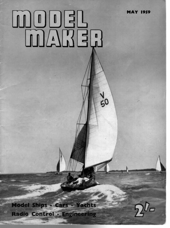
vii MODE MAKER IMPROVING THE PERFORMANCE OF MODEL YACHTS Part Two By R. H. MORRELL Heading picture shows an “M” Class model set up for checking of alignment of fin and skeg Below: Sketch of simple home-made gauge for checking height of L.W.L. Opposite, top: “Hull right—finish right—sails right”. A recent ““M” Class model which began to score points even whilst still being tuned up Opposite, bottom: “Ship shape and Bristol fashion.” A successful 10-Rater designed and built by Mr. W. Brown of Bristol M.Y.C. Note the very clean wake, indicating an easily driven hull ie the previous instalment of this article, comment was made on the fact that quite a few model yachts of mediocre performance are cabable of considerable improvement, if suitable modifications are carried out. Careful analysis of a yacht’s possible defects was discussed, and it was pointed out that certain types of design defect are final and unalterable. Fortunately, we also found that a number of commonly occurring faults are capable of correction— generally with gratifying results. It may be remembered that our analysis pin-pointed four main types of defect, and in each case the work involved in eradication of these adverse factors should be found Having now a clear to be very well worthwhile. perception as to the nature of our problems, let us turn to the practical consideration of exactly what is to be done with them, considering each defect in turn. Fin and/or skeg out of alignment. The first step is to find out whether or not our particular model embodies this fault, either by reason of the fin and/or skeg being out of vertical, or by their fore and aft axes differing from that of the hull. Occasionally one sees a model where the defects are obvious to the unaided eye, but usually considerably more accurate means of checking are Wasyensscrew : NCIL SCREW SUDING BLOCK 2’x3/4°x1″ WOOD soa.cowe.rco a BASE 6″x6″x 78″ necessary. Now this is not quite sq easy as it sounds, for the double curvature of a yacht’s hull presents difficulties. It is a different matter, of course, to check a model whilst under construction, as one has the building board (or the flat surface of the top layer in the case of a laminated model) to ensure that the hull’s L.W.L. is truly level. But the attempt to verify the accuracy of fin and skeg on a finished model has probably puzzled more than one model yachtsman. A satisfactory method is illustrated in the photograph. Although she was a good performer in other ways, the model being checked was under strong suspicion in this particular, as her performance on port and starboard tacks was not identical. First two upright members, in this case of 2in. x lin., were screwed to base pieces which could be clamped or screwed to the bench. There were carefully checked to ensure that they were truly vertical when assembled in their working position. It will be noticed that the kitchen has to suffice as a workshop and, as the kitchen cabinet-cum-workbench was not sufficiently long for the model, an extension piece was used at one end; this being supported at its outboard end by the cooker top! Ah, well! Difficulties exist in order to be overcome, and there is a lot of satisfaction to be found in the getting around of a problem, even if the family do regard one’s ingenuity with unseemly mirth! So if your working facilities are not all that you would wish, don’t let it bother you, for many a fine model has been built with limited facilities, whereas even the most elaborately equipped workshop is no guarantee of accurate work. It is true that adequate equipment will speed and facilitate production, but patience and willingness to be painstaking are the qualities upon which good workmanship depends. A straight and true length of timber was then obtained, and clamps were used to secure it to the uprights. If no clamps are available, this horizontal member could be secured to the uprights with screws, but clamps are preferable as they allow the horizontal member to be easily adjusted to different heights above the hull. It was next necessary to so position the hull, keel uppermost, that her L.W.L. was truly level, both in a longitudinal and thwartships direction. The bow was placed against one upright member, and a packing piece put under the stern to lift it the required amount. Further packing pieces of suitable thickness were then used under each gunwale (i.e. edge of deck) near the mast position, one on each side. By careful movement of these two blocks, in a fore-and- 230
MAY,1959 aft direction, it was then possible to bring the hull into adjustment with the L.W.L. level in both directions. This is checked by means of a simple home-made height gauge, as illustrated in the sketch. This may be placed on the bench top and slid around the hull, and the ‘3-point’ support of the hull will readily allow its being adjusted as required. If a reader seeks to use this method with a hull on which the L.W.L. is not marked, he can carry out this check in a different way. First, he should draw a line (thwartships) on the bench at about midships position. If he then carefully checks the height of the gunwale above this line, measuring on both sides of the hull, he has then only to adjust his packing blocks to and fro until he gets an identical measurement on both sides. (If the hull were so badly made that the two gunwales were not of equal height, we would, of course, be in difficulty, but this should not really arise.) With the model properly set up, checking of the alignment can now proceed, always remembering to view the hull from as many different positions as possible. First stand a short distance away from one end of the testing jig and, closing one eye, take a sight with the other along the centre-line of the hull, moving your head slightly until the edge of the distant upright (what you can see of it) lines up with the near one. If your model’s fin is out of true this should now be clearly visible. A short plumb line, with a small bob, can now be suspended from the horizontal member and, altering its length as necessary, it may be tried at various points along the hull, fin, and skeg. In each case the point of the plumb bob should exactly coincide with the centre-line of the hull. The horizontal member may now be lowered until it just touches the fin, when its edge should fall along the centre-line of the fin. In cases where the keel is detachable, it should now be removed. This will permit the horizontal member being lowered, aac a further check being made along the jointing ace. Anyone applying these tests is advised not to hurry the process, for a second careful look may reveal an inaccuracy not at first noticed. Should your check-up reveal that your model is free from these faults you will have eliminated one avenue of error and the test will have been worth- while. On the other hand, it may well be that you have located a defect which has been greatly handicapping the performance of your model. In the case of the model being tested in the picture it was found that: (a) the fin was not truly vertical; (b) the longitudinal line of the fin was slightly out of true with the centre-line of the hull. As the keel was detachable, the first fault was rectified by a little adjustment of the joint faces, the hull being rechecked several times during the process. Fault (b) was overcome by a slight reshaping of the fin to bring its after-edge truly central. ALL-STEEL CONSTRUCTION contd. from p. 229 insulators in them of the type as shown in the sketch at the bottom right of the drawing here. They are easily seen in photographs. The “crows-nest” on the foremast is reached from the top of the ship’s galley by a “Jacob’s ladder.” This is of steel wire rope with round wood rungs lashed to it. An extension of this ladder goes up the foretopmast starting from the canopy over the crows-nest. Other features of the foremast are the platform for the steaming lights, the anemometer (or wind speed indicator) platform and the small topgallant mast which carries the directional aerial. Electric cables lead up outside the mast to which they are clipped, to these fittings, and also along the backs of the yards to the lights. In the event of a failure of current the steaming light has an oil lantern which can be hoisted to below the platform along two steel guide wires. “Tribal” class destroyers did not appear to have a main steaming light which is usually carried in all ships, 15 feet above the fore light, if they have two masts of sufficient height to allow this. 231


