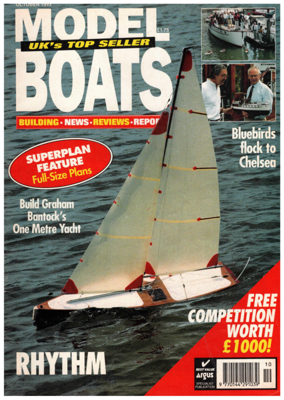
- GRAHAM BANTOCK’S Rhythm Exclusive Full-size Superplan for a competitive R/C One Metre yacht by a top designer and manufacturer which won the National Championship in 1990

FREE ITION WORTH rd | (IKI SPECIA PUBLICALIST TION ae 0144°29
Exclusive Full-size Superplan for a competitive R/C One Metre yacht by a top designer and manufacturer which won the National Championship in 1990 SUPERPLAN PROJECT Robert Vice poses with his model of Rhythm, built Srom the Superplan. All photos: Ray Brigden. Owing to the large size of this model in Introduction relation to the Making a start in R/C model yachting can be a daunting experience. There are so many decisions to make; size/class of model, kit or scratchbuild, new or secondhand, model shop or mail order, maximum allowable published size of our etc. Undoubtedly, the best piece of advice is, find your nearest local club and pay a visit. They can show you what’s available, where to get it from, and most Superplan format, this month, the important, the classes they are operating. There isn’t much point to making a race-winning ‘XXX’ class boat if they only sail ‘YYY craft! To seek out the club, try the local library if you are aware ofa sailing group in your area, Superplan contains one half of the otherwisea call or letter to any of the model boating magazines will bring the main yacht drawing plus necessary info. Telephone the Secretary and go along to their next meeting. If there is no local club, but two or three of you gather together to the Rig Drawing. The second half of the yacht will be published on another Superplan next month, and on the reverse will be the Sail Drawing. 34 GRAHAM BANTOCK’S Rhythm sail, then contact the MYA Information Officer (address at end) for more information. There are a large number of classes, currently seven ‘major’ and about the same number of ‘minor’ categories. It is generally considered that the newcomer should make a start with a 36in Restricted or a One Metre. The physical size and relative simplicity of the latter, plus the fact that it’s spars must be of aluminium ally or wood, rather than exotic materials, means that a competitive yacht can be scratchbuilt from wood construction and not be outclassed the moment it hits the water; MODEL BOATS OCTOBER 1993
if built and rigged well, it may be expected to remain competitive for Building Guide some years to come. Maximum and 1. The first thing to do is to clear enough space to lay the plan of the hull panels out flat. To reproduce the shape accurately, cover the sheet of ply with carbon paper, then carefully lay the plan over this and draw over the lines on the plan. Thin panels are 0.8mm ply. 1.6mm can be used but may be too heavy. The tricky bit here is the bottom panel (A) as it is shown as only one half and therefore you have to mark out a mirror image of the side shown. It does pay to spenda little extra time and effort on these panels as an incorrect fit will be a disadvantage at a later stage. When all the panels are drawn out cut around the outside of the carbon lines, leaving enough to sand down to the lines to minimum figures are set for draught and fin/ballast weight and there is a minimum total displacement. No more than two channels of control are ‘ permitted and exotic materials are prohibited from the hull construction. The construction requires no building jig; planking is not involved and hard chine construction is relatively straightforward, and the materials are commonly available at model shops. Background to Rhythm Sails Etc., of which Graham Bantock is the owner, initially produced the Rhythm kit in the late 80’s as a five panel hard chine design hull. No building jig was required to construct the kit as panels were supplied to shape. Rhythm won the first One Metre National Championship in 1990, and continued its success over the years at open and club events around the country, including a hotly contested MYA Ranking Regatta. The kit was withdrawn from sale last year and replaced by Jazz which features a grp moulded hull. Sails Etc. have now decided to release the Rhythm plans with the aim of maximising the potential boost to the number of One Metres and model yacht club members. What better way than by reaching 20000 readers through our pages! So if you have always wanted to get into R/C model yachting without spending a fortune on exotic materials, here is the golden opportunity. Why not take it now? For further information concerning the Model Yachting Association, write with an sae to the Information Officer, 115 Mayfield Avenue, London N12 9HY. This month, ROBERT VICE shows you how to build : Rhythm from the Superplan, ensure accuracy. The same should be done for all the pieces on the plan including the deck panel. It is very important that the deck panel is not twisted as this provides the hull with its shape and strength, therefore any twist will distort the hull. 2. Mark a centre line on the bottom panel (A) between points 350 and 500mm from the aft end. Also mark a point 65mm from the aft end on the centre line. Turn the panel over and mark a 20mm square centred 65mm from the aft end. 3. Tape the hull panels (A, C1, C2, C3 and C4) together with the centre line marks on panel A on the outside. I used the 2in wide brown packing tape, but the All Weather Sellotape would do just as well. The tape must run along the joints on the outside. Take great care to ensure smooth joints as any ridges will have to be sanded down later. 4. Chamfer the edges of the deck panel (D) using 120 grit paper to give a good fit to the hull. When satisfied with the fit, tape in place temporarily. Adjust and chamfer the edges of the bow piece (F) and the transom (E) to fit the hull and deck correctly, then tape in place along each edge. Sight along the assembled hull and, if it appears twisted, adjust the M yachters are all too aware that the Rhythm is not a new design, indeed the first national championship for the 1 Metre class was won by the original in 1990 and the design continues to win to the cost of many top skippers even now. So you may be wondering why, three years later, I am now reviewing this well taping of the deck until satisfactory. 5. Cut four pieces of glass tape 970mm long. Mix 24ml of resin/hardener and using a small brush proceed to tape and resin the inside of the four joints between the hull panels. With the surplus resin, coat one surface only (the inside surface) of each of the fin box components (G1-G4). Also glue the pot doublers (H1 & H2) together and leave to cure for at least 24 hours. The plan assumes that the pot used is of the size supplied by Sails Etc, If this is not the case the pot doublers and the hole in the deck will have to be changed slightly. Epoxy resin (not glue) is recommended, and the types which cure slowly are better than the fast cure proven design. The key is that I am varieties. doing a review of the plan, and that it is intended to be published by ASP plans. An updated range of plans has been badly needed for many years now and I, like many, believe the 1M class to be the one that will bring many more new faces When cured, remove the deck and make up a paste made of resin, silica and glass spheres. (Glass spheres are used to thicken the resin mix into a paste, therefore talcum powder or similar will do the same job.) Run a fillet around the internal join between the hull and the and Graham Bantock provides instructions for the Rig Drawing any of us regular model to our sport. What follows is a guide to anyone who might be tempted to build from this plan. MODEL BOATS transom. Use more paste to glue together the fin box components (G1- OCTOBER 1993 G4), taking care that the fin blank will be a loose fit to allow for painting of the fin. Also run a plain resin mix over the joints between the hull panels, to ensure a water tight joint, if you think they might be a little dry. You can afford to build these hulls with water tightness and strength as your prime concern because the class rules require the hulls to be ballasted to a generous weight. 6. While all this is drying you can start on the deck. First decide which way up you like the deck. This might seem a silly instruction and it is not for cosmetic reasons. You may prefer the radio tub on one side or the other, it depends whether you are left or right handed. Bear in mind how you hold/pick up your current boat, or try picking up a clubmates boat. You should find that one hand feels more natural than the other leaving the other hand to unscrew the pot, unplug the batteries etc etc. So think now or forever hold you peace. 7. Drill the holes in the places indicated on the plan, for the following components; mast tube (J18), rudder stock (J9), pulley block (J10), and keel bolt hole. Do not drill holes for the mainsheet fairlead eyes or shroud eyes yet as the placing can be better judged later in the build. 35
bolt hole. When satisfied with the fit, glue in place using plain resin mix on all matching surfaces. Hold the components in place with either clamps or weights, while the resin cures. It is most important to ensure that the fin box is at right angles to the deck at this stage: use a try square or set square and check it as often as possible while the resin sets. The more often you check it the more certain you can be of getting it right. Be sure to leave it to cure fully. 9. When cured, drill holes for the shroud eyes (J11) from the underside of the deck. Drill holes for the following from the top of the deck: mainsheet fairlead eyes (J3, J4), and sheet guide eye (J13). Drill holes for the backstay eye (J8) in the transom. Bend eyes (J3, J4, J8, J11) from the wire to the required shape and push into place. Do not add the sheet guide eye at this stage. Mix sufficient paste (about 12ml) and fillet all deck beam to deck joints and around the top of the fin box, pot doubler, and on the underside of the wire eyes. Then add the winch and servo plate (L), and fillet into place. Leave to cure again. Shape the ‘cut out’ area of the winch and servo mounting panel (L), to suit the items you intend to fit. I found that the commonly used Whirlwind/Futaba combination fitted easily and I see no reason why any modern combination will not fit. 8. The deck can be turned top side down. When the fin box has cured sufficiently, it and the deck beams (K1- K3) and the pot doubler (H1+H2) should be arranged onto the deck. Ensure that the fin box is the correct way up and that it is correctly centred over the keel 36 10. Using 32ml of resin mix, coat the inside of the hull and the underside of the deck except for a strip 8-10mm wide around the edge of each, and the rudder doubler area. When the resin is cured enough to allow work to continue, trial fit the deck structure to the hull. The fin box is supplied overlong and will require some adjustment until it fits without distorting the bottom of the hull. When a satisfactory fit is obtained, mark the position of the fin box on the inside of the hull. Remove the deck and abrade an area 20mm all around the box position (and 60mm forwards). Mix 40m of resin mix and coat the previously uncoated edges. Convert the remainder to quite a thick paste and put into a small polythene bag. Force the paste into one corner, snip off the corner to leave a small hole and use like an icing bag to apply a 5mm bead all around the inside lip of the hull. Lightly coat the bottom of the fin box and apply the remaining filler along the deck transom joint. 11. Carefully drop the deck structure into the hull pushing it down until the top surface of the deck is flush with the top of the hull. Tape it in a few places. Check the alignment and adjust if necessary before continuing to tape the entire deck edges. Tape at frequent intervals to achieve a fair deck edge. Use a palette knife or a tool made from thin ply or card (even a lolly stick) to make a smooth fillet inside between the hull sides and deck panel. Remove and save the excess filler. Turn the hull upside down to ensure that the paste is running towards to the deck. Check to see that the mix is not too runny. You need it all to remain at the deck/hull joint. Then leave to cure. 12. Use more filler to form a fillet around the fin box/bottom panel joint, the deck/transom joint, and to add the rudder doubler (B). Cut several 40mm pieces of glass tape and wet out with filler paste. Apply these to the bottom panel just ahead of the fin box where the mast step (N) will be placed. This is needed to reinforce the hull against the large strains on the mast. Add the mast step and fillet into place. 13. When cured, use glass tape and resin mix to reinforce the fin box/hull joint and deck/transom joint. If you leave it to cure for more than a week or so, a layer of wax builds up from the resin, therefore it has to be removed with abrasive paper before the fresh resin will bond satisfactorily with the first mix. This curing time does depend on temperature, the warmer it is, the faster it cures. 14. When the resin has cured the fin hole can be cut into the bottom of the hull. To do this, mark on the centre line positions 405mm and 465mm from the stern and drill into the hull using a 3mm drill. Use a broken hacksaw blade to work outwards from these holes until the fore and aft edges of the fin box are reached. Now mark onto the hull the section of the fin and cut it out using the hacksaw blade and/or small files. Carefully adjust the cut so that the fin is a loose fit to allow for painting the fin and the paint which will accumulate on the edge of the cut out itself. 15. I used a Sails Etc wooden profile fin. It is possible to make your own, obechi, spruce, cedar, or balsa with a carbon fibre covering can all be used. However the manufacture of fins and rudders is an art in itself and I would advise beginners to start of using a pre-formed set of foils. Mark the top and bottom profiles on the fin, ensuring that the length along the leading edge is no more than 440mm. This gives a total draught of circa 410mm, i.e. approximately 10mm less than the maximum permitted by the TYRU One Metre Rule. Trial fit the fin into the hull and adjust if necessary. Mark the keelbolt hole onto the top of the fin. Drill a 45mm deep hole where marked with a 4.5mm drill. Use a drill and file to cut an oval recess in the top of the fin large enough MODEL BOATS OCTOBER 1993
to take the washer and nut. Use 400 grade paper to remove the square leading edge of the fin and form an elliptical or parabolic leading edge shape – similar to the plan view of the bow bumper on the building plan. Two shapes are shown on the plan for the rudder, so cut the rudder to the shape you prefer. Care is needed to create the correct section. Shape the leading edge as for the fin and cut the top of the rudder to the profile shown. The fin and rudder blanks provided by the usual suppliers take a lot of the hard work out of the fin and rudder building and give you good cross sectional shape to start with. I would recommend that anyone building for their first time should buy in these items. Abrade the area of the rudder stock which will be glued into the rudder. Smooth the surfaces of the fin and rudder with 400 grade paper. Wax the keel bolt(J6), (use furniture polish or car wax or, if you have neither of these, grease) and assemble into the fin with the washer and nut. Tighten with your fingers. Mix 4ml of resin/hardener and use some to glue in the rudder stock into the rudder. with some remaining resin thickened to a stiff paste, fill the recess in the top of the fin. Leave to cure. Drill the rudder stock hole 65mm from’the stern through the bottom of the hull and doubler, take a look at the plan again to check the angle that this hole has to be drilled at. Start with a 3mm drill and enlarge progressively to 6mm. Bolt the fin in place (the bolt should undo without difficulty if properly waxed), and insert the rudder into the hole drilled for it. Use a small file to adjust the hole until the rudder correctly aligns with the fin. Then enlarge the hole to take the 8mm diameter tube. Cut the tube to the correct length and abrade the lower end to ensure that the resin will get a good grip on it. Use a small amount of resin mix to glue the tube in place and fillet it to the doubler. Replace the rudder to keep the tube aligned while the resin cures taking care to avoid glueing the rudder stock into the tube, and leave to cure. 16. While the rudder assembly is curing, your attention can turn to the fin and lead. This deserves all the care and effort that you can afford, as it is very important to get your yacht floating correctly on its water-line. I know many experienced model yachtsmen who deliberate a great deal over this stage but it always pays off in the long run. One Metre leads are available from all of the usual outlets and as far as I am aware, all are compatible with the standard fin section. So ensure the fin fits into the récess cast in the lead ballast casting, enlarge if necessary and check the approximate fore and aft and transverse alignment. The casting requires a variable amount of work to produce a smooth finish and it is imperative to achieve the correct weight. The class rules permit a maximum weight for a finished fin + ballast of 2500 grams. The castings normally come over weight and usually require trimming to tidy them up. MODEL BOATS OCTOBER 1993 Use a ‘Surform’ blade (a convex one held in the hand and drawn towards you works well, sold in any good hardware store) to remove material quickly and finish with a 2nd cut file, 120 grit paper followed by 400 grade wet & dry abrasive paper. Find the fore and aft centre of gravity of the lead by balancing it on a piece of scrap tubing. This point is marked on the plan, and your mark must be the same distance from the leading edge of your fin as it is on the plan. Abrade the bottom of the fin ready for the resin, and hold the lead in a drilling vice or similar. Three quarter fill the recess in the ballast with a mix of paste. Push the fin into the ballast and with the excess, form a smooth fillet between the fin and ballast. Ensure the alignment is correct and leave to cure. Again the more often you check it, the more likely you are to get it right. If any excess resin runs down the side, it can be removed with care after it is touch dry. After the fin has been added and finished check the total weight and adjust if necessary. 17. Remove any tapes remaining on the hull and deck and abrade the outside of the hull and deck all over finishing with 400 grade paper. Mix 48ml of resin mix and coat the outside of the hull and deck, any untreated timber remaining in the hull and fin and rudder. Fora first class finish on the deck, fin and rudder, continue to coat then with two pot polyurethane paint or varnish (available from most yacht chandlers) when the resin is freshly cured (less than a week); or use SP product ‘Hi Build’ a thick epoxy coating which can be used to build up a thick, easy to rub down coat, in a short time. Alternatively continue to use epoxy mix to coat the items. If using exterior paints allow the resin to cure and then rub down thoroughly before proceeding. The final finish of the hull will depend totally on the time and effort spent now so splash out and buy a new piece of wet and dry or two! 18. When the hull surface and deck are finished continue to fit out the yacht. Make a hole in the radio pot large enough to pass through the winch and servo plugs. Cut the hole low enough to avoid the deck beam. With the pot lid screwed on firmly, press the pot into place. Taking care not to disturb its position, remove the lid and carefully drill three equally spaced 1.5mm holes through the pot and into the doubler and drive in three self-tapping screws. Seal the pot/deck joint with a fillet of silicone bath caulking compound (sold by most good DIY stores – the compounds that smell of vinegar are the right ones). To complete the rigs you will need the following materials: Make These items may be made providing you have the right equipment but most will probably prefer to purchase them. Rigging screws are not essential to rig a One Metre as an alternative using cord and a bowsie is shown on the plan. However they do permit a better degree of control over the rig. Bowsies are not particularly difficult to make by hand, just tedious. Discarded toothbrushes are a good source material for these items and allow for a degree of colour customising. Prepare the fittings Cut the 5mm knitting needles to provide three pieces 50mm long and three pieces 85mm long. The shorter pieces will be used for the kicking strap levers which are used to prevent the main boom from kicking up under the load from the mainsail. File the ends smooth and add the notches where shown. Bend the longer pieces to form the backstay cranes. The bend should be 25mm from the lower end and needs to be through 70 degrees only. Wrap the lower end of each backstay crane with electrical tape until it is a good fit inside the mast top. Cut the 3mm knitting needles to provide three pieces 145mm long and three pieces 100mm long. The longer pieces will form the spreaders which provide essential extra stiffness to the (to be continued) And now, the rigging drawing … he drawing shows the basic layout for any of the three permitted IYRU One Metre class rigs. Dimensions are given on the plan for the lengths of all spars and positions of all rigging items. 37
metres %in diameter alloy tube + + + + F + + F F Packet grommets with 8mm hole for %in diameter Packet 20mm x Mein diameter split pins 5mm aluminium knitting needles 3mm aluminium knitting needles 300mm x 1.6mm diameter stainless steel wire 300mm x 1.25mm diameter stainless steel wire metres 0.55mm diameter stainless steel wire metres 80 lb breaking strain dacron 1.85 metres 12.7mm diameter alloy tube 1.4 metres 12.7mm diameter alloy tube 1.1 metres 12.7mm diameter alloy tube FF O rings for %in diameter Non snag hooks (or split rings) Small plastic balls Packets three hole bowsies Make + Medium crimps Es, Tp ed eee 25 gram counterbalance weights HS + —” Nee M3 Rigging Screws (may be omitted) ee © S Ree WWWNHMRRrMWWWrE WMD Oo Now Ww} AS aaRNA TE es GTEC ie Item Description MY Those items marked with an asterisk in the MY column can be purchased from model yachting suppliers. A number of model yachting suppliers are able to offer packs of all (or most) of the items listed above. Expect to pay more for packs containing anodised alloy tube which will look neater and will resist corrosion better. Some of the suppliers already provide rig kits for One Metre class yachts, but these will make use of their own versions of the fittings shown on this plan. Contact those listed in the supplier section for prices and availability. HS Those marked in the HS column may be found with some ingenuity in a good High Sheet. Try fishing tackle shops for suitable weights to use for the jib boom counterbalance weights, as well as crimps, stainless steel wire, split rings, dacron cord and plastic balls etc. Hardware stores should be able to provide split pins (perhaps not stainless steel ones though) and grommets. Knitting needles from the haberdashery store please and not from your mum’s, wife’s, girlfriend’s sewing box. Tools and Materials To complete the rigs you will need the following tools and materials: —S mast when it is loaded by the rig. The ends are notched with a 3mm deep vertical cut of the junior hacksaw. The shorter pieces are fitted into the jib boom counterbalance weights. These may be special items purchased from the model yachting suppliers, or ‘bombs’ bought from a fishing tackle shop. There are various types but the ones with a swivel provide a neat hole in the right place once the swivel is wrenched out. Buy 20 or 25 gram versions if your booms are %in diameter and 22 gauge but larger ones if the tubing you have is heavier. Make up the various pieces of wire for hooks and the kicking strap as shown on the plan so that rigging can proceed smoothly once you start. The value of good quality tools will be appreciated when working with the larger diameter wire. Masts Start by marking out the positions of the holes and measurement bands on the mast tube as shown. All dimensions are taken from the extreme top of the mast thus making it quite a straightforward task. Double check the dimensions and use coloured adhesive tape to add the measurement bands if you intend to race the yacht at any time in the future. It is very easy to do this job now and their presence will help when adding the rigging. SRB ARREST TEES Drill the 1.6mm diameter holes in the fore-side of the mast for the forestay hooks, and in the sides of the masts for the shrouds. Note that two holes are required in each side of the mast, one 38 Junior hacksaw Hand drill plus 1.6mm and 3mm diameter bits Good pair round nosed pliers Good pair end cutters Small file Vice Steel measuring tape Cyanoacrylate glue (Superglue) Plastic padding (or epoxy glue thickened with talcum powder or something similar) Scissors Adhesive tape (coloured, minimum 3-6mm wide, plus insulation tape). The instructions assume that all three rigs will be made at the same time. above the other and as close as possible for the shrouds. Drill the two holes at the lower end of the mast for the split pins which form the gooseneck from the back of the mast to ensure they are in line. This is quite crucial as otherwise the mainboom will not swing freely. Drill the 3mm diameter holes through the mast from side to side making sure they are at right angles to the previous holes. Placing a piece of wire through the holes for the gooseneck may help. Cut the lower end of each mast to length so that they can be stepped in the yacht at the right level. Place the spreader rods through the mast so that they are exactly the same Mark out and cut the %in diameter tube for the booms. File the ends smooth and mark out the main booms for the holes and drill them with the 1.6mm diameter drill. Fill the ends of the jib boom with Plastic Padding as shown and allow to cure. When it has cured, drill the holes for the split pins and jib boom counterbalance weight rod. Glue the split pins in place with cyano glue. The position of the counterbalance weight is adjusted when the sails have been added to the rig and then glued in place. length each side and lock in place with a Adding the rigging application, some epoxy glue thickened the booms and tie dacron cord where shown to provide attachments and spot of cyano glue. Then mix up some Plastic Padding or, better for this with some talc to the right consistency, and makea neat fillet where each protrudes from the mast. Any excess glue is best trimmed off before the glue has properly hardened. Push the grommets and O rings onto adjustments. Add the split pins to the gooseneck wire and pass them through the mast. Splay the ends so that the eyes are tight up against the back of the mast. Push MODEL BOATS OCTOBER 1993
SAILS ETC Almost all the materials required for this yacht are available from a variety of sources, and we have listed suppliers elsewhere. However, for your convenience, SAILS ETC have made available the following items: Rig Pack for Lo Tech rigs (for one each number 1, 2 and 3 rigs, no sails) £60.00 Fittings Pack for Hull £42.50 Ballast £25.50 Foils (aminated timber fin and rudder) £14.75 Building Pack (resin, fillers, brushes/syringes/glass tape pack) £25.50 Short Kit (comprising Fittings Pack, Ballast, Foils and Building Pack £100.00 All prices include postage and packing to any UK address. Please note all prices include VAT and are valid until the end of 1993 only. SAILS ETC are at 141 High Street, Kelvedon, Essex, the forward end of the mainboom onto the upper end of the gooseneck wire and fill the end with Plastic Padding or thickened epoxy glue. Also glue the splayed ends of the split pins with epoxy glue or Plastic Padding. Leave to cure. Add the kicking strap levers, cord and controlling bowsie Place the mast and main boom units in the yacht so that the shrouds can be made off to length properly. A piece of rigging wire is passed through the elongated hole/slot until it passes out of the top of the mast. Then it is formed around a crimp and pulled back into the mast. Pass each of these shrouds over the spreaders and make off the lower end onto a rigging screw if you are using them (alternative A on the drawing), or form an eye and add a bowsie and cord if going for the lo tech version (alternative C on the drawing). Note that it is possible to attach the body of the rigging screws permanently to the yacht and just have the rigging screw ends attached to the shrouds (alternative B on the drawing). This means that each rigging screw will have to be completely undone to remove a rig from the yacht, but it also means it is impossible to lose the rigging screw bodies. Moreover the hooks which are required on them are avoided thus ensuring the rigs do not behave like fishing rod, line and hook when being transported! Clench the ends of the spreaders tight over the shrouds. Insert the backstay cranes and make up a bowsie and cord to form the backstay. Make up the wire forestays by forming an eye in each end ofa length of rigging wire. The required distance between the eyes is given on the plan and can easily be achieved by banging nails at the required distances into a piece of timber to act as gauges. Add the bowsies and cord to form the upper forestay adjustment and the line which lifts the aft end of the jib boom (topping lift). Add the lines from the continuous winch loop to form the jib and main sheets. Note that a special type of hook is used to attach and adjust the main sheet. The O ring holds it in place. A bowsie permits independent adjustment of the jib sheet and a non snag hook or a split ring permits it to be attached/detached easily. Seal all knots with a spot of cyano glue or heat seal with the tip of a soldering iron. MODEL BOATS OCTOBER 1993 CO5 9AA. Tel: 0376 571437. Road, Salisbury, SP5 3BY. Tel: 0722 324677. Swan Models, The Bungalow, New Barn Park, Swanley, Kent, BR8 7PW. Tel: 0322 666363. Housemartin Sails, 51 Edinburgh Drive, Birkenhead, Merseyside, LA3 ORJ. Tel: 051 608 8252. Mac Fit, 1 Lakeside Court, New Brighton, Wirral, L45 1NS. Tel: 051 639 7106. Cast Lead Bulbs Ken Butler, 10 Leaholme Gardens, Stourbridge, West Midlands, DY9 OXX. Winches Suppliers Kits, Hulls, Fittings, Sails, etc Sails Etc, 141 High Street, Kelvedon, Essex CO5 9AA. Tel: 0376 571437. Tony Abel, Highnoon, Petersfinger Whirlwind Winches, 49 Aberdale Road, Leicester, LE2 6GE. Tel: 0533 883309. Peter Wiles, 1 Courtenay Road, Poole, Dorset, BH14 OHD. Tel: 0202 744101.


