- Sails and Rigging: The text provides a detailed “Table of Dimensions” for various cutter and sloop rigs on 36-inch and 40-inch L.W.L. boats and 10-raters.
- Novel Construction Methods: A segment describes an unconventional, low-cost method for building model boat hulls (both yachts and torpedo boats) using paper and cardboard over wooden ribs and a keel.
- Engineering and Club News: The issue also features “Practical Letters” from readers (including a design for an “Easily-made Blowpipe”), a report on a lecture about the Amsler planimeter given at the Institution of Junior Engineers.

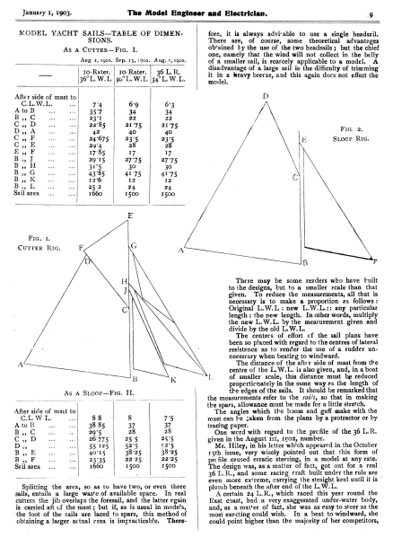
January I, 1903. The Model Engineer and Electrician. MODEL YACHT SAILS—TABLE OF DIMEN. SIONS. As A CuTTER—Fic. I. Aug 1, 1901. Sep. 15, 3902. __ After side of mast to C.L.W.L. a | 35°7 Cc, F © 55 E,, F | B,, J 4 ” Ee | ” B. gy 40″ L. W.L |34”L. W.L. 74 Ato B B,, C C,,D DyA By K ais — a 69 6°3 34 34 23’1 22°85 2 22 21°75 22 21°75 40 24°675 40 23°5 23°5 17°85 17 17 29°4 29°15 3E5 43°85 Sailarea… Aug. 7, 1902. 10-Rater. | 1o-Rater. | 36 L.R. 36″L. WL. 28 | | | 4.7 1660 | | 1500 252 Fic. 2. Stoop RIG. 28 27°75 12°6 9 fore, it is always advicable to use a single headsail. There are, of course, some theoretical advanteges ob‘ained Ly the use of the two headsails; but the chief one, namely that the wind will not collect in the belly of a smaller sail, is scarcely applicable to a model. Sisedvaniage of a large sail is the difficulty of trimming a heavy breeze, and this again dors not effect the 27°75 30 I” ee ae 24 2 1500 E Fic. ¢ CuTrer Ria. B F There may be some readers who have tuilt to the designs, ba to a smaller scale than that the measurements, all that is given. To reduce Original L.W.L : y pa ength: the new lenge: In other ‘words, rey the new ry Ls mearurement given and The centres of a cf the sail plans have divide by the old L.W. been so placed with regard to the centres of lateral resistance as to render the use a a rudder un necessary when beatirg to windw \ L. 88 38 85 Ato B B,C C,,D D,, B,, E we B,, F Sailarea… 29°5 26°775 55125 40°L5 wa sis 23°35 1660 8 37 37 28 25°5 £2°5 33°25 28 25°5 52°5 38°25 22°25 15co 22 25 Ia | Splitting the area, so as to have two, or even three sails, entails a large waste of available space. In real cutters the jib overlaps the foresail, and’ the latter egain is carried aft of the mast; but if, as is usual in models, the foot of the sails are ‘laced to spars, this method of obtaining a larger actual crea is impracticable. There- The distance of the after side of mast from the centre of the Iso given, and, in a boat of smaller scale, this distance must be reduced same way es the length of the measurements refer to the saz/s, so that in making the Sets, allowance must be made for a little stretch. The angles which the boom and gaff make with the mast can LA taken from the plans by a protractor or by p: tracing One ardwith by re. to he prcfile of the 36 L.R. given in the Au Ist, I¢O2, number. r. Hiley,in his jetier which suonsed i} n the October 15th issue, very wisely pointed out that this form of prcfile caused erratic steering, in a model at any rate. The design was, as a matter of fact, got out for a real 36 L.R., and some racirg craft built under the rule are even more ex’reme, carrying the ea keel until it is © plumb beneath the after end ofthe L. Acertain 24 L.R., which raced this year round the ach coast, bad a very exaggerated under-water body, , as amatter of fact, she was as easy to steer as Se srioet exectingcould wish. In a beat to windward, s could point higher than the majority of her Louipellors,
The Model Engineer and Electrician. January 22, 190}. took me eight weeks of evening work, and cost under four shillings, as will be seen by the description of the building up. Model yachtsmen on the lake have frequently commented favourably upon her speed and construction. 89 are made of Y-in. thick wood, fastened together with pins. The motor I first used was of the type described there also; but it was not powerful enough. e field-magnet bobbins were, or, rather, their cores, were made of two % in. rivets, softened in the fire, and wound with 3 ozs. each of No. 24 D.c.c. wire. The four armature bobbins were 3% in. diam. and Fic. 3.— PApgR-MADE Mopgt Torpepo Boar Fic wound with 2 ozs. eacn of 24 D.C.c. wire. Length of field-magnets, 23 in. Length of armature, 2 ins. ; I¢in. i next bought another set of castings, but these proved to be too heavy. ow, I have a smalf Knapp motor that I bought for ros. 6d., and witha 22-in, propeller ; it drives the boat about 334 miles an hour. Compared with steamers, this speed is not a very good show of its capabilities. The average cost per hour of 2.—PAPER-MADE MopgEL YACHT. Fig. 3 is of an electrically-driven boat, also of paper, and is 4 ft. 8 ins. on deck, 7 ins. beam, 6 ins. deep, an carries 4 lts.-ot lead to keep her steady. The batteries, of which there are six, are of the bichromate type, and are similar to those described in THE MODEL ENGINEER Cc Deck 4″ ~ Cc Putty “ ie” (A CARDBOARD A 7 _f-—] | JP B about x In, Fic. 4. PAPER ELULLS FOR MODEL Boats. METHOD OF BUILDING Up. for November 15th, 1901. To keep the casings acidtight I soaked them all in paraffin wax, and ran the wax down all the joints. Candle wax will not do, as the acid eats it away slowly, and comes to the top like froth. They are 5 ins. deep by 4 ins. long by 2 ins. wide, and running is about 3d., not including fur the wear of zinc: but only for acid. I will now describe how I built my hulls, after reading the construction of which readers will begin to say that sucha hull will have all shapes ; but I can say with proper
care it can be made to look as well as built-up yachts or boats. The deck is first cut out to shape and warped by steam to make the desired sheer. It must be understood that this deck must be in one piece, and made of }-in wood; therefore, the curves of the deck cannot be got both ways. have curved mine longitudinally by warping. For the electrical boat the keel is cut out of a I-in. plank—a leaf ofan o!d table in my case—with end pieces pinned or screwed on to form the stem or stern pieces. he deck is laid on the table with the necessary pack- ing pieces under to preserve the sheer, then the keel is screwed on. The sections or ribs are cut out of ¥ in. wood, leaving about 3 in. wide all round, see Fig. 4. Thin cardboard is glued from side to side (A, A), and all along the deck where the ribs touch and right up to the Before this is done, cut small pieces of end-pieces B, B. wood } in. square, and glue between the ribs on deck, to prevent the paper going in C, ’ The Model Engineer and Electrician. go January 22, 1903. Practical Letters from Our Readers. [The Editor invites readers to make use of this column for thefull discussion of matters of practical and mutual interest. Letters may be signed with a nom-de-plume i/ desived, but the full name and address of the sender MUST invariably be ‘attached, though ily intended for publication.| An Easily-made Blowpipe. To THE Epiror oF Zhe Model Engineer. doubt many readers of the AZZ. have felt the necessity of having a small blowpipe. I Flame h i fin is considerable, and tends to crack the enamel when she heels over to the wind. At present I am making another keel for my 10:rater—a solid one of 4-in. wood— and cutting out slots where the ribs come. The keel is made out of a lath 136 ins. wide and ¥ in. thick. This is shaped to follow the curve of the ribs, and the fin is let in. Plenty of putty should be used to hold the fin and the keel and the paper together. In yachts a cabin is not advisable, as water might possibly get in and would lead to a mess, which would distort the shape of i From Gas Bracka Steam is out of my line a‘ present, owing to a small boiler which I had exploding. In conclusion, I will say that the 10-rater cost under 4s. The deck cost Is., lead ts., enamel 1s., and the other Is. goes for glue, &c. The sails are made of ordinary linen. The Institution of Junior Engineers.—At a recent meeting of this Lustitution, held at the Westminster Palace Hotel, Mr. Kenneth Gray, presiding, a paper was read on ‘The Pianimeter, explained simply without mathe- ter W. J. Tennant, A.M.I.Mech.E. matics,” by Mr. some introductory remarks as to the necessity of such an in- strument as the planimeter for the use of engineers, who could by its means have calculations perform:d for them automatically, the author proceeded to describe the con- struction of the Amsler planimeter, and considered its principle of operation analysed graphically for a simple r summarised the principal features figure. of the instrument’s action as (2) The sweeping o} upstroke and downstroke areas, two (or more) in number by a bar whose length does not change during the operation, but which lies upon the whole more obliquely to its line of travel during the one stroke than during the other, i gure to possess area and not merely length without breadth; (4) The automatic subtraction by the roller of these two classes of area from another so as to present an indication of their difference. This indication is the area of the figure, no matter how irregular, around the boundary of which the tracer has been run. The question of looped indicator diagram areas was considered ; Coffin’s averaging instrument was also described, and its action illustrated. In conclusion, the author investigated the conditions obtaining when the pivot is encircled by the outline of the area to be measured. A From Bellows AN EASILY-MADE BLOWPIPE. have found the following one very useful for small repairs, and also for sweating with soft solder. It consists of a piece of brass tube (A) of about % in. diameter and 5 ins, lorg. A hole is drilled at 2 ins. from one erd, and a piece of gas tube (B) inserted and soldered into place. A piece of glass tubing, 3 in. in diameter and about 7 ins. long, is procured, one end held in a gas flame, and, when red hot, drawn out toa fine point. The thin part will be required to be scored all round before breaking off. e rubber tube, and the glass tube D to a bellows by another piece of rubber tubing ; the bellows shou!d have an airbeg attacked to it to enable the maintenance of a constant pressure and prevent having a jerky flame. —Yours truly, G. GREENE-KELLY. Monkstown, co. Dublin. Hulls of Model Steamers. To THE Epiror oF 7he Model Engineer. —May I offer a suggestion to that portion of yours readers interested in model ship building?
February 5, 1903. The Model Engineer and Electrician. tested for insulation. A test between the two terminals should show an insulation resistance of at least a megohm. The projecting ends should, of course, be tightly clamped together during the test, and if the condenser shows too Fic. 3.—CompLere CONDENSER. wa a co c TM o ° i=] oa a » a ° i. 3 i=] 5 ° ad o ° Q WOODEN o low resistance, it must be dismantled and the paper sheets inspected rigorously for punctures and other indications of imperfection. If it tests up all right, then the projecting foil ends may be melted down solid and soldered to the °Q ung up by a pin stuck throagh the extreme corner of each sheet and allowed to cool. After cooling, any superfluous wax is scraped off by means of a very duil knife, @ interest to many Qa HE follo wing hints on the practical details ~» making T a condenser for an induction coil, will ofdoubtless be of 125 When the sheets are all assembled, they should be squeezed down tight in an ordinary screw letter press, and ot Hints on Condenser Making. BLS Highgate Model Yacht Club. Fic. 1.—LAYING THE SHERTS. or a strip of square-edged thin steel, the paper being laid on a true, smooth, hard sur’ace during the scraping. Before paraffining the paper, each slip should be closely scrutinised for pin holes, irregular thickness, and traces of metallic oxides ; any slip that is not plainly free from all of these imperfections should be thrown out. . e work of assembling the sheets of paper and tinfoil will be immensely facilitated by the use of a simple jig, such as that illustrated in Fig. 1. This is simply “THE annual distribution of the prizes won by the members of this Club at their out and home matches during the past season, took placeat the residence ofthecommodore, Mr. C..J. Findon, and avery pleasant evening was spent. One of the subjects under discussion’ was the celebration in an appropriate manner of the fiftieth year peted for during the summer on the ponds at Highgate SHELL7 COLE? open to any model yacht club, to be called gate Jubilee Challenge Plate.” The ‘‘ The High- Committee of the Club were instructed to prepare a scheme of sailing and prospective dates, and submit it to the general meeting in engraving ; one strip projects at the left-hand end of the **nest,” the next one at the rig at-hand end, and so on. None of the foil slips must touch each other except at the March, enough subscriptions baing promised in order to make it a success. The Hon, Secretary announced that, in response to their long-continued agitation respecting the banks of No. 3 Pond, the Parks Committee of the County Council had met a deputation of the Club, and,he had the welcome intelligence to convey that the banks would be put into a proper state of repair before th racing commenced, so that all those sailing their yachts there would be able to do so in more comfort than hitherto. The Officers and Committee were thea elected to serve for the ensuing year: Commodore, Mr. C Findon, Holloway; Treasurer, Mr. J. Field, Haverstock Hill ; Hon. remaining forty sheets built up on top of these. Fig. 2 illustrates one of these connectors, which consists merely of a sheet of copper. with one edge rolled around and soldered to the end of a piece of No. 12 rubber covered copper wire. The flat part of the copper sheet should measure J in. by 3 ins, after the wire has been soldered in place. Secretary, Mr. W. T. Vine, 15, South Hill Park Gardens, Hamps‘ead. A NEA calendar for 1903 has been sent us by the Genéral Electric Co., Ltd. It is in the form of an ‘‘Angold” arc lamp, the globe of the lamp being used for a tablet of tear-off date slips.
72 The Model Engineer and Electrician. The Model Steam Turbine Competition. we are now able to I give a more detailed reportissue, of this competition, and N accordance with our last 7. append a few remarks upon the majority of the entries, placing them as nearly as possible in order of it. The first seven entries run each other very close. 1. W. Hatcot HiNncston.—This design bears the imprint of practicability, the drawings are very fair, although they are not the best received. The only point open tocriticism, besides the fundamental one—the question of efficiency—which will in a measure apply to each and all the designs submitted to us, is the construction of the nozzle ; the shape of the hole in the case would not, we think, in every instance conduce to a good finish. The turbine is a little small owing to its intended use in a model steamboat, but can, of course, be made to larger dimensions with beneficial results, with perhaps the same nozzle. The description and proposed construction of the turbine seems very good indeed ; but, as we shall publish this the prize article in its entirety, we will leave our readers to form their own opinion of its merits or demerits. 2. W. purpose. Davip SHANNON (Govan).—Very neat drawings describe the construction of the turbine, but its design is open to criticism from several points of view. The fixi of the blades is good, but we think the maker would find it difficult of accomplishment. Nothing is provided to prevent the steam escaping radially by centrifugal action. A ring enclosing the blades, like that shown in two of nt. governor is prop:sed in this design, but better and clearer working details are necessary. The description of the design is very short. A second alternative design was entered by this com- petitor, but it arrived too late and was therefore disqualifi is design is for an outward radial flow turbine, and will be reproduced in due course with the others. P. H. Batts .(Ilford).—A good sheet of drawings was received, but the design of the turbine is not so good as in the prize article. The turbine is of the steam wheel description with three wheels arranged on a triple expansion principle, and although it is worthy of a trial we are not at all sure that it would make a really practical steam engine. . O. D. NortH (Bromsgrove) has designed a model Parsons (parallel flow) turbine and direct-coupled dynamo. The drawings are not good enough for direct reproduc- ELFORD (Brondesbury).—A simple design of the well-known siren whistle type, the rotating disc being provided with holes drilled obliquely, three jets of steam impinging on the disc at the pitch fixcle of the holes. © not anticipate that any power will be obtained from a model built to this design. 8 L. (Birmingham).—Design is a modified but rather small model De Laval. The drawings are poor, Lut the article is of fair length and quality. 9. W. B. N. (Kesh).—Drawings insufficient and very sketchy. Judging from the information embodied in the article, the method of cutting the curved blades does not seem to be praeticable. 10. S. C. W. (Darwen).—Drawings are poor, and the design, as it stands, is not practicable. 11. A. L. (Poole).—This design describes what is really a rotary engine and not a steam turbine in the ordinary sense of the word. 12, W. (Leeds).—This design is a modified m of Hero’s engine; but the details have not had sufficient thought. The drawings are useless for reproduction and the article is poor. 13. G. B. S. (Stockport), T. A. (Lancaster), and G. S. (Hull) each send in designs for a model steam turbine exactly similar to that entered by P. H. Balls (Ilford) 0. 53 but the drawings and the articles received are BLANEY (Stepney) sends an ingenious design, which, being based upon the results of some practical experiments, he thinks gives reasonable promise of success. The turbine is not a copy of any particular type, and is strictly a parallel flow machine, although the steam enters at the centre, and finds its way out of the turbine at the outer ring of blades. The chief difficulty of the design would appear to be the construction, and some of its efficiency as a steam engine is sacrificed to rendering it mcre easy to 1 cave 1 make. Asin all parallel fl F need to be as small as possible, and the design does not altogether lessen this difficulty. » R. Woop (Middlewich).—A very fair article has been sent in by this competitor, which describes some interestiog devices in the design, which is a modification of a De Lavalturbine, with a 4-in. wheel. The speed reduction gear is worthy of consideration ; but the blades of the turbine wheel are not shown in detail, and, as far as we can gather, they are not arranged in the best and most scientificmethod. The drawings are not suitable for our February 19, 1903. tion, and the details of the design are not worked out in the fullest manner. However, he shows considerable ingenuity in the method of forming the blades on the rotor, and on the casing (stator); but we think that efficiency is very largely sacrificed to the exigencies of manufactuie. The article accompanying the design is very good. very poor. * 14. J. W. W. (Teignmouth).—This design is for acompound De Laval turbine, but is without special merit from any particular point of view. e remainder of the entries are of the ‘‘ thumbnail sketch ” variety, and cannot be cons‘dered as serious attempts to grapple with the problem. Model Yachting Association of Lancashire and_ Cheshire, T pool and district, a meeting of the clubsin inLiverthis O further the interests of model yachting locality was held on the 21st inst., the outcome of which was that they decided to form a model yachting association for the whole of the above district. G. Willmer, Esq., of the Wirral Model Yacht Club, was elected President. Dr. Boreham, of the Yacht Club, was elected Vice-president, and the Hon. Sec. is E. ynne, of the Wirral Club, whose address is 31, Clarence Road,.Seacombe, Cheshire, and who will be glad to hear from all the Hon. Secs. of model yacht clubs in Lancashire and Cheshire, with a view to them joining the newly formed association. FRICTION IN BALL-BEARINGS.—Mr. J, Golden, in a paper read before the American Association for the Advancement of Science, illustrated an apparatus used to determine the friction of ball-bearings of different sizes The results seem to show that, for pressures and speeds for which they a:e suitable, ball-bearings give a loss by friction far less than that of an ordinary bearing with imperfect lubrication, but not much less than that of a finely polished and thoroughly lubricated bearing.
174 The Model Engineer and Electrician. Steering Gears for Model Yachts. Bid gear connected with the boat. The building itself fellas more or less a beaten and well defined The making of the sails depends principally on the skill and practice of the craftsman; but the would appear to be always open to some new trial. This is the more extraordinary when it is remembered thatin some parts of England (the North in particular) the rudderis entirely ie ene with, excepting perhap; wi It will be seen, then, that the water below the hullis very little disturbed, and thé rudder will be moving through aie which is passing away aft parallel to the keel of the b By W. H. WILson-THEOBALD, M.A. ae fe ae apparatus of a model yacht has progiven rise to more experiments than any track. February 19, 1903. fin keeler has little under water body, and rather glide over than through the water. et an extreme case be taken fet Suuppose the hull was so shallow as to pieenoy leave me water entirely undisturbed. On referring to Fig. 1, ich represents the sheer and load water line “of a very allen craftin A and B, it will be seen that the water will flow aft in the direction of the arrows, a! turn the rudder through an angle of 45 aefor the fi of water to strike its surface at the same angle n many instances the ased, due to the fact that | placed, or else that the sails are not properly desired course. As a consequence, the boatrequires con- stant weather helm to keep her straight; result, loss of Pitsshould always be borne in mind that the rudder, excepting whenin the same fore and aft line as the keel, tends to check the speed of a boat; and in consemodel yachtsquence it should be the aim of every man to so set his sails, and balance the centres, as to dispense with this dragging tendency as much as possible. uses of a rudder on a real sailing boat may be The St 1. To put her about 2. To check divergence from course, due to a foul or o’ free puff ; 3. To alter course To prevent collisions. So far as.the model yachtsman is concerned, Nos. 1, 3, and 4 do not enter into the question at all; and there only remains to be domed the best means to meet the re- quirements o’ In opposition meihe “no rudder” class heel are the advocates of many contrivances bs sheet and by india-rubber bands, a, Fic. 1. Now let the under body be increased so that the water lines immediately below the load water-line would, if produced, cut the head of the rudder, as shown in Fi In this case the water, instead of flowing aft parallel to the centre line o oat, comes in a sweep round the quarter and engages on the top of the rudder at an angle; oe m t which areao ipieaiel to answer the purpose of a controlling IBand at the tiller. A description of these various plans will be given; but, for simplicity, the common weighted swing rudder holds its own with the best of its opponents. The swing rudder has stood the test of many years’ trial, and, from its introduction, when the owner had to carry a complete set of different sizes in his pocket to the present day, ce only two, or even one, are needed, it has always answered its purpose. Small Tcerations and additions have been made for pre- venting a jibe, tefor getting back to the original course if thrown off by any external cause; but the original idea still remains the steering E will, doubtless, be admitted that a perfecttae actical x to meet every change of eircananpaiiecs is a Sposability;3 but it is any surprising h actual result of a han i oa— can be Sheed by st means of automatic The shape of the rudderis a poiit apt to be overlooked by the model yachtsman, and yet this has considerable influence on the sailing of the boat. It should be of such a form as to obtain the best results with the least possible area, and so avoid excessive frictional surface and loss of speed. Further, its area should be so distributed as to ensure it receiving the pressure of the water to the best advantage. A fin boat with the rudder hung ona skeg, or the after fin, requires a different pattern a a bate boat with its rudder on the stern post. The Fic. 2. the m for this will be explained as simply and clearly asnee, The modern the rudder at an angle further and further down, according to the fulness of the lower water-lines, as in Fig. 3. In a design, the lines which show the flow of water round the body of the boat to the best advantage are those called the diagonals; and the planking, more or less, naturally falls round the boat in the direction of these diagonals, which therefore should always be put in, if only to fair the drawing. And now, what has all this theory to do with the shape of an rudder? Harking back to Fig. 1, it is seen that all the pressure of the water runs parallel to the keel, and therefore, ifit is required that the boat should answer
The Model Engineer and Electrician. February 19, 1903. the helm quickly and without undue loss of speed, it will be necessary to have a large area of rudder to obtain the necessary pressure, when only turned through a small angle. Further, as at all depths of water the pressure peas in the same direction, the top of the rudderis en equal value as the bottom; and, therefore, it may spinmetrcal for its entire depth, as is shown in Fig. i either r B. ang Fig. 2 it can be argued that the water directly below the L.W.L. is of most use for obtaining the pressure, and therefore it will be advisable to put as much area as possible at the head of the rudder, and an outline as in Fig. 5 will be found to give the best results. In the keel boat, Fig. 3, the water is of use right down the stern post, and the area of the rudder can be spread out as is shown in Bearingin mind the fact that a large rudder turned to an excessive angle with the keel retards the speed, the arguments used may be summed upthus :—For a ver shallow. bodied fin boat the rudder should be of large area and fairly symmetricalin shape; as the body of the boat Kaen LL a Ae Fic FIG. 5. B 4. Fic. The following additions could be made to any of the swinging rudders given later on, and will not, therefore, be referred to again. Very often, on starting a model on a run from the edge of a condewith the b FIG. 3. increases in depth, the area may be decreased and spread out, so that its largest surface is situated where the flow of water will strike it at the greatest angle with the centre line of 175 out ez voyage. These two rudders should answer every pondiat of weather; but there ue. ae appliances to e added to make them more comp! boat. This distribution and decrease of area may be con- tinuedin the case of a keel boat until the least possible surfaceis found which will give the most satisfactory an absence of wind, due to trees in the background, or to spectators watching the start. Ifa fairly heavy rudderis shipped to suit a possible strong breezein the middle of the sailing ground, the chances are that the boat will jibe before well under way. Thereis this misfortune. results The practical side will now be dealt with. old idea was to havea set of As before mentioned, the weighted ooss suit various strengths of wind and directionsof cow Nowa ys thet consists usually of only two, the common nanan of which are shown in Fig. 7 (A and B). for These diagrams are shown half ‘ full size,” as suitable The width through the a 10 rater of 36-40 ins, L.W. larger should be about ¥ in., noot more than 3% in. The smaller of themis generally made of a piece of brass plate, in the centre of which isa ball of lead (c) ‘running on a threaded axle. This rudderis used (if one comes more abeam, the ballis run aft, until it is found to be of not sufficient power, when itis unshipped and the larger one substituted. Practice ane can tell the owner ‘when this change is necessary. arger type is con- structed of two pieces of brass seonealy held together on pieces of hard wood (d). The after edge is left open to receive various pieces of lead, according to the weight remember that a modelis usually measured for Rem quired. rating ‘with the Aeaviest rudder shi n making such a rudder, the angle of the bottom must tbe mftcient to prevent the possibility of the leads falling Fic. 7.—FORMS OF WEIGHTED RUDDERS. viz., opposite to the boom, and is attached to the mast just above the gaffjaws. It should be just slack enough to not interfere with the rudder swinging well to leeward. Nov:, suppose the boat jibes, the boom flies over and engages with the cord, the cord pulls the rudder hard over, and at once brings the model round until she jibes back again andis off on the original course. Fig. 8 will explain the routine. In A the boat has just been sent off, The dotted line shows the cord. In
The Model Engineer and Electrician. 176 B she has jibed, and it does not need to be pointed out wrinkle. course, as shown in A Another misfortune may be a collision when beating to It was said that the headsails should not be held amidi A further advantage windward, the result of which is to throw the boat on the opposite tack. February 19, 1903. fighting against the mainsail. The consequence would probably be that the beat would make continual efforts to go about and each time fail, making little or no headway. A diagram, Fig. 9, will help the novice to appreciate this that, with the strong weather helm given, the stern and bow will swing round, as shown by the dotted lines. The result will be that she will jibe again to the original Here again the remedy is quite an easy matter On each side of the stern post, fin, or rudder itself, are screwed small pieces of brass, which can be twisted roun Fic. Fic. 9. cd — TRIANGLE GEAR. headsails) would be flying loose, and could not prevent the mainsail from doing its duty in putting her back to the original tack (A). This is shown in Fig. 9. over, but remain ina straight line with the keel. If then some weather helm were actually required to keep her on this new tack, she should fly up to the wind and go about be anything but satisfactory. The mainsail would be trying to help her round, whilst the flat headsail would be ARRANGEMENT. Fic. 11 to lie parallel to the L.W.L., see Fig. 7 (a). When starting on a certain tack, twist round that piece of brass which is on the weather side ofthe boat. Now when she is knocked on to the opposite tack the rudder will not swing at once, owing to the absence of any rudder working. This power to tack may be further helped by hitching a short line from the boom to deck, so that when on the wrong tack the boom is held almost amidships. 10a.— PLAN OF WEIGHTED TILIER . e intention cf this article was to deal with steering gears for model yachts; but it is no use pretending to tackle the question, unless the theory and working of a rudder is more or less understood. Craving pardon for the amount cf ‘‘cackle,” the other gears referred to will now be treated. The first variation of the ordinary swing rudder, already described, is one which is permanently attached to the stern post or fin, but which depends upon a tiller on deck for its control. This is shown in Figs. Io and Ioa. In its simplest form there is merely the lead weight ad-
The Model Engineer and Electrician. February 19, 1903. throwing the wheels out of line. On the other hand, this elongation of the back carriage results in a longer total wheel base, whichis allin favour of steadier steering, and absence of side-slipping tendencies, with the further = vantage that the rider’s weightis thrown forward, and s nearer midway between the two points of wheel. cotitact with groun Another disadvantage of this position of motor is that the belt is extremely short, and will give more trouble through stretching or variation of length, slipping being more pronounced, and the grip on the engine pulley reduced ; the vital point, however, is the length of the rear frame, and however ae and carefully made there will be difficultyin keeping t ar wheel als in the back stays (from wheel centre to saddle cli placing it forward of the seat pillae, aeningsugg the front panel of the frame instead o! k triangle, and by dropping the crank bracket ace have got the motor into a lower posiition. Placing’ the motor in the angle formed between the seatpost and lower diagonal tube would also admit of the crank chamber En oe to both tubes, so vastly strengtheningthe whole frame vebsaatiayand at a vital pn also pes ohgood long belt rear carriage of either ordinary or motor bicycle cannat well be too short, and it is policy’to bringin the rear-wheel tyre as may to the seat-post, hghes allowing ample space for mudguard fittings, and t! position of the rider can be regulated by fixing the saddle on a forward instead of rearward saddle pin. Of course, I am fully aware of the difficulties amateurs have to encounter in attempting to make alterations iin frame clerign when using standard fittings, and it is, of course, an easy matter to extend the back carriage ; yustery ~ ‘alee the frame front involves special lugs With —ard to the remarks contained in Messrs. Miller & Morrison’s letter ve brazing, I may say that, whilst agreeing with them to some extent, I still think that others as well as myself have at times given su’ iently minute instructions to enable any ¢hinking agen who has already advanced far enough to build the engine to also braze the frame; and, although the results of badly brazed joints in a motor frame would be more serious, the chances of defective joints as against a light bicycle are all in favour of the former being sound, will burn usually braze well, or the amateur will up the tubein the process when it zs thé T. “. Haw .ey. 750-watt Steam Dynam To THB EpITOR OF ZheM Engi Dear S1r,-~Please allow me to Tok “= R7th. ae ioe his criticism of my design for a model steam-crane. passing of points and crossings was a detail I had catieely ae designs I am very sorry to ce so many excellent passing through your er without bein, thoroughly criticised, as I am sure bey could be greatly improved there With regard to the design now appearing for a 750watt steam generator, might I offer a few remarks? The cee thing that appears to me to be defective i| s the crankhaft. The cranks are shown at right ang’es, and this ibaa iealanes weights. ow, there is nota two- crank high-speed engine on the market with a crank made as described. If the cranks are to be at right angles, then they ought to be balanced with weights on the webs. I should suggest putting the cranks opposite. This would be better than that shown; although thereis still a rocking couple tending to lift the engine at the | | | ends. 189 Thisis caused by the H.-P. line mooring.up while the L.-p. line is moving, and vice versa, (No —The line here consists of piston, rod, crosshead, aa con- rod.) As this point has been discussed in your necting paper in connection with the al boat engines, it will not be necessary to say any The doors for getting at the yeting parts of the engine are shown fixed on with fourteen set pins. This is seldom done in practice, as two, or four at the most, suffice to hold on the largest doors. The design I had in my mind when the pom peliiion first appeared consisted of a two-pole ironclad dyn of the Avery- ae type, with the poles placesvertically, driven by a simple engine of the type shown o page 43of the coerent ese only of more substantial construction. A two-p e dynamo anda much simpler engine would find moregn among model makers. A set of 100 or 200-watts capacity on the above lines would, I think, meet a decided want, as 750-watts is rather a large unit for the average reader. Yours sincerely, DaviD SHANNON. Govan, Glasgow. Model Yachting Correspondence. To THE EDITOR oF The Model Engineer. R SI1R,—In my article on ‘‘ Dug-out” models, flict appeared in THE MopEL ENGINEER of Sep tember 15th, 1902, I suggested ae use of Prout’s elastic up the layers. I think, however, that glue for joining the experiences of a friend should be put before your readers as a warning when using this substance. It is recognised that the glueis excellent for small jobs, when it can be used in the same way as sealing-wax, thatis by direct application from a flame. This methodis of course impracticable for a long joint, owing to the I have used it in an of the glue. immediate ile We ordinary gluepo Tiesaaa until now, never appreciated My friend, antocantelys has; and he assures me that its inflammable it burst into fame in the pot (owing no doubt to a small overflow) to a most alarming manner; which was very difficult to extinguish. Perhaps, in these circumstances, I may be allowed to qualify my instructions and suggest the use of ordinary glue instead of ‘‘ Prout’s elastic.” Yours truly, London, W. W. H. WiLson THEOBALD. THE JUNIOR INSTITUTION OF ENGINEERS. —A large number of the members paid a visit on the 17th January to the New Electricity Works of the Metropolitan Borough of Shoreditch, Whiston Street, on the banks of the Regefit’s Canal. They were pont round by the pra Electrical Engineer, Mr. C. Newton — and mbers of his staff. Following * close upon Mr. the Rounthwaite!’s Paper on Marine Boilers, eal before attention Institution on the 2nd of January, particular are the boiler house plant, in which was directe installed four water-tube Babcock Wilcox marine boilers. The engine-house plant consists of two vertical low-speed the Wallsend continuous current Westinghouse ‘generator, of 800 k.w mminute. On Saturcapacity; speed, 90 revolutions per be paid to the East uth Metropolitan Gas Company, through facilities inaly extended by Sir George Livesey.
- o The Model Engineer and Electrician. The News of the Trade. – February 19, 1903. engines made by this firm, readers should obtain the satsloete we reviewed in our issue of December ist last. Price 6d. p [The Editor will be pleased otreceive for review under this eae sam es and particulars ei aterials for amateur use. It o, m c merits of the goods submitted, or to abstain from inserting a review in any case where the “goods are not o sufficient interest to his readers.] A Compound Launch Engine. ; We reproduce herewith an illustration of the Ardwick Engineer- ing Company’s Compact “Compoun cylinders of ‘this engine are in unch Engine. The one casting, with the receiver A New ge GBAR FOR MODEL YACHTS, BY HE CLYDE MopEL DocKYARD. AB consists of polished jeametel Al casting wahe slides E raimitine m plane, d filed V shaped 6ietheguides for. the sliding partG. The end B is slotted, an means of the slot ‘hi (the end A meanwhile having beenis rewed to deck), the oat fine of the terrplate |is perfectly true with e hel: rud he sliding crosspiece ‘s ald |5 pon nd its sides are V. n be roovi that oO fit ac ly, and slide easily n sides C of base, andis slotted at H. The iller K is a triangular plate, and worksin he slot H. One end of the tiller is fixed by turning or filing , and screwing in. of he helm post head, and passing it through he slotted hole and fixing it on witha nut . by simply soldering it,So that the tiller- end ‘a being fastened by an S hook ora main hawse and the chain or rope fro: e main boomKe fasten ed to the link which $5 or main hawse. Now, if ‘the caine tye is moved to end M ofK,the rudder will be fixed centrally. enhowever, ARDWICK ENGINBERING Co.’s ComMPpouND LAUNCH ENGINE. between the two, the H.-P.c.being 2% ins. and L.-P.c. 4 ins. diameter. With a steam pressure of 180 lbs. and the engine running at that the tiller-plate has aJarger or smaller amountro moverient action, £Gb at the laced in the cen’tre, the rudder will ‘be given half its fal‘py only. not be alittle the model yachtsman wiloon learn to0 gaugeecune exactly how much rudder action to give his narrowend, the rudder will b ieavd be at the other end (M) of the tiller, the rudder aie t. Complete weight 2§ozs., price only 23. post free. Special terms“to ‘clubs, ais, in one dozen lots.
214 February 26, 1903. The Model Engineer and Electrician. riveted or screwed on properly. Queries and Replies. (3) Coal or charcoal may be used, ressure of [For conditions see page 190 of our last issue.) Dynamo Connections. Rotary Transformers: H.[8021] R. (Saltley) ‘rites ©Ay I anould be glad if you vould kindly a me an outline of how to make a small transformer to e curren! at, say, 100 volts onatransform: it to about 6 or 8 volts. volts I wane ai would be¢ glad” you would answer me the following to make a transformer P’ question :—Su to 6 and charge accumulators 4 a in parallel, is it necessary to connect up the shunt circuit of both machines in series with one another, or does each to have its own shunt cecal ? ? machine require Sketch (not reproduced)is sent of , is more than we can do in the il bear your buggestion in mind andsee ¥ article on the subject ise be had. e might suggest “that you take I is, we are EO qery — se ican) A Query N° 8059. é nol % FirE GRATE FOR MODEL MARINE BOILER, the fuel will fall over and block up the flues. (4) You will find this a costly boilerin copper,and we suggest the use of steel 5-32nds in, thick, perhaps galvanized. D. W. D. (Chichester) r your valuable correspo pndent. 5 Mr. Wilson ae oo a ise me in the following?—I hav Dn SF Sa ged a 4 a So , [7909] Sail Plans for Model Yachts. Query N? 8021, SHUNT DyNAMOS IN PARALLEL. two machines from our handbook “Small Dynamos and Motors” regulating resistance of e mac! to Sismibute the!Joad as neeneASeS. See recent replies to queries on diagrammatic |sketch appended should show clearly t 6narod of connecting up. this sub [8035] Books, &c. H.S. R. (SoPath Kensington) writes: Could you tell me ne best book to get on ne slide rule? Mine is manu- f a bookon the Stand:urd voltmeters, animeters, &e.,tedin electric nd that no one text book Inches the lot. Whee could I get anyinformation on the work I s! ould be expected to do in the patent offices of any of our Pe a ee teturedby Ta son Bros., Leeds, and is of the Grant pattern. Al (1) “The Slide Rule and Watch Calculator,” published by the Scientific Publishing Co., 53, New Bailey Street, Manchester, price free; or “ The Slide Rule,” by Pickw orth, from went 1S BS post “The Slid 2s. Co., Paternoster cauare, E.C., price W (2) We ante” by i “G. BI:aine, E. & F. N. Spon, 125, Strand, W.C. know of no book dealing with volt ‘a ammeters alone and exclusively,biut most makes are dealt with in Rankin Kennedy’s . ¥ aaa Installations very ful y. el Pp. H. arine Boile: (Manchesterwrites: (1) Would this |pees (sketch noe veprodtead) 1 ft. beam, havin boa be suitable for driving a . 6in. e double cylindered engine, cylinders 14-in. bore b; pee stroke, (2) i = 3 se cman = BB” fight stat‘ions, Qgery NF7909. The boiler ends and tubeplate and dome I intend to have bras castings. Will it be necessary to put in Jongltudinal stays uw ould be the best ikind fuel to burn, coal or charcoal as ieth like tokeep upa otorking pressure of 50 lbs. ? ® The boiler. shel will be made out of 4 sheet copper double rivete 1) According to the formawhichis given at greater length ii n our new handbook on “ Model Steamer Machinnery,” price post free, the boat would appear to be provided with a pair Or Sane of revs. per Be Breese a (0 Ibs. ample power; and to work them a than the above, en about 230 s rf: the boiler a little and using a larger number of tub es. as doi that over-cylindering a nos steamboatis as bad Remember ng to a locomotive. @ Very little staying if any) will be required with cast ends toa boiler. No stayis required for dome if Sart PLAN FoR Mopet Yacut. We are indebted to Mr. Wilson Theobald for this reply to your query. me) pte depth of keel suggested, viz., 6 in 22-in. mple le for a The position of mast depeands entirel n the s of effort and lateral resistance; Roughly speaking, the mast is general found to fall atoF”about 4-1oths of the L.W.L. from its ore é: (3) The welent of bulb must necessarily be sufficient to sink the ‘boat to ther is can be found experi- mentally by placingig, weighs(or lead) in the hull or on deck and 1 to the weight so found. sq. ins. in the mainsail. (4) The Enclosed is an outline ot Teg of mutton mainsail and jib, giving the measurements.
The Model Engineer and Electrician. 388 Sea-going Model Yachts. .. M. Savac HE various ati which bave “appeared. from time to time’in yachts have building, at sailing of model ing, and ins eeeion to all who take been a source of interest a pleasurein this fascinating pastim Almost without exception, all these articles bave dealt of small dimensions, which may with model yachts possibly interest the majority of your readers, especially near the sea those who are not fortunate enough to live or any large sheets of water, where thereis greater scope for pursuing the sport under conditions which more nearly resemble those governing the actual sailing of large yachts. It is, therefore, for such readers who may live rear the sea, and for those who may, perhaps, feel disposed to build model yachts of large dimensions that this article is chiefly written In dealing with such models a ey) 35: to 45 raters, the conditions for and more especially sailing them on large sheets: ofater s to contend with strong it must be clearly keptin mind that at sea, where not on! winds, but also with al cutrents and choppy seas, are ose which exist where model e: April 23, 1903. Greatest beam amidship, 1 ft. 6 ins. Freeboard amidship, 8 ins. Length of fin, 33 ins. Depth of fin 46 lb. 0 ozs. Total ballast. Displacement, 109 Ib. Overhaneioprer, I ft. Mainmast,”nigh fromn deck, 5 ft. *. 3 in Mainboom Gaff, 3 ft. Bowsprit eacaed, 1 ft. 7 ins. (12ins. inboard). Topmast, 3 ft. 9 ins Topsail aay vidlog 30 a some topmast. 0 3 Spinnaker boom, 5 ft. Sail areas— Mainsail Topsail Foresail Jib… ai 2a nes eee oes . 1,890 sq. ins. 455 625 ss 45 427 we 4, “318 we 270 55 … im see 39530 55 Flying jib… Total ai ves pea A. Rating EWE * SA. Ww. their sailing aaniiten Some of your readers, when at the seaside, may have been spectators of what are called ‘‘ Mocel Yecht egattas,” at which Hons of from 2 ft. to 3 ft. in length are placedin a choppy sea with a eon breeze, the so- called race generally consisting ofa drifting mateb, the tide or current taking the little boats quite out of their to have been the course, and the winner generally proving best drifter. Now with boats of large dimensiens and greater displacement this is not the case, as they may be designed and built heavy enough to withstand the currents and to ae their own very wellin even what sailors call a moder. ea. Moreover, in the matter of expense, the aiference |fa cost of building a boat of say 3 ft. W.L. and 6 ft. W.L. is trivial, the great disadvantage being, of course, that in the latter case it requires more than one person to lift it into the water, besides requiring the attendance of a small rowing boat an carnal to enable the person sailing to work his model to advantage. Having in the course of a few years built even lnege models, my experience may be of interest to those may be inclined to try their hand at a sea-going yac! I have found that the most suitable dimensions “fox such a craft are those represented by my model cutter Hilda, a 40-rater, which was exhibited at the Holborn Town Hall at the last Convermeons of the Society. As this yacht has sailed over 100 miles at sea, in all kinds of wea*her, and her satisfactory performances bave amply repaid me for the time, trouble and expense in constructing her, I think she may be considered as a safe type to follow bothin build and rig. The designing and actual building of models has been dealt with so ably in various articles in THE MODEL ENGINEER, that I will briefly state that the designs of my yee were drawn out for me by Mr. Wilson Theobald, andthat, at my request the boat was designed as a snes and not as a racer Subject to a few ior ‘alterations, his actual dimen- sians of hull were adhered to, and a few particulars may be of interest. Length “ BemA ft. 4 9 5 ft.‘biins. 40lb. 102 5 Ib. 15 ozs, .. . Lead ballast and zinc fin . Loaded rudder… 38°83. Construction.—The timbers are of oak, }4-in. sided, and 3-16thsin. moulded, spaced 6 ins. centre to centre, tion, and this was accomplishedin the following manner: A new 5-gallon petroleum drum, fitted with a screw stopper on top, served as a boiler, and after having made a wooden steam box, 3 ft. by 5 ins. square, of 1-in. wood, well screwed together, and painted inside and outside with red lead, I fixed an indiarubber pipe from the top of the drum to the interior of the steam. tox through a hole cut in the end, and placed the drum when half-full awater ona gas.-stove. After a very short time sufficient am was generated, and conveyed through the pipe to after about ie small bers lying iin the steam box, and the box was re- withdrawn as oaitted. These the timbers moved,thenandfound to be quite pliable, and whilst hot, were twenty miffutes’ steaming, one end of were bent round into position corresponding to the temporary building sections; they were then tied to temporary longitudinal battens, running fore and aft, the battens being ultimately replaced by the strakes, which were finally screwed to the timbers. About 2000 screws were used altogether, he gunwales are of American oak, 1 in. square; the keel, which runs inside the ribs,is of English oak, 24ins, 1in.; the strakes as= mahogany, % in. thick, sawo into strips 2 ins. wide; the deck is one gee= American s, &c., are whitewood, whilst the ‘masta, bowsprit, el”aeithetand of lancewood, as —_ strengthis the eyed strain at sea .—The mainstays, forestay, bowsprit ieand Ri, topmasBt ass are a made of fine galvanisedwi starboard rire various quake s The port and running teckle are ack and doxel aye, and the the acticn of seamade of om sealine, as, owing totohave all tackle and water, itis absolutely necessary rigging of a suitable kind. Itis most important that in such a model the hoisting tackle and rurning gear must be so arranged that all sails can be hoisted, trimmcd and lowcredin the shortest possible time Furthermore, it is necessary to have rather stouter and
Aoril 30, position, 1903. the whole The Model Engineer and Electrician. manipulation occupying a few seconds. I have also combined with it the graduated helm given by the triangle system, which has already been explained in THE MODEL ENGINERR; so that if any of your readers will care to construct a gear in accordance with my specifications, I think hey will find it practical, effective, simple, and stron he following description may facilitate your readeis ‘o understand the working drawings, which are half full size and applicable to a 10- or 20-rater, with a stern post at any angle to the deck. It is, of course, presumed that the rudder is weighted and fixed to the stern post, or fin, by pins, the rudder-shaft being also fixed to the rudder, 417 used by means of the pin, is quite independent of the other parts of the gear. ‘igs. 1 and 5 are drawn half full size, whilst Fig. 6 is he thick of the b ate maké ane “Binning through a tube under the counter to the eck. Fig. 1 shows the gear in elevation. A is the ruddershaft fixed into a slotted ball B, and held in position by ~ means ofa pin; the slot in B is broad enough to allow the tiller E, which works on a pin at C,’to engage the _ To throw the tiller E out of gear, all that is necessary is to lift it in the direction of the dotted line M, when it would make a comple‘e half circle and lie backwards on deck $ in this posi ion the ball B rotates freely on its own axis within the inner circle B, shown in Fig. 2. Cis a slotted disc, which revoives upcn an under disc D, and is made adjus‘able by means of two milled-head (Har¥F Fu Size.) p 3° O# 10; ance, yet in practice it is simple and effective, and may be made by any amateur who has a lathe and knowledge of brass working. The Junior Institution of Engineers. T the mee’ing of this Institution held on April 3rd, at the Westminster Palace Hotel, the Chairman, Mr. Kenneth Gray, presiding, the first paper read was on the ‘* Evaporative Trials of one of the Water-tube Boilers for the Chilian Battleship Constitution,” by Mr. H. E. Yarrow (member), of London. The paper described trials catried out to ascertain the comparaiive merits of a small grate and rapid combustion, as against a larger The boiler, of the grate and slower combustion. Yarrow type, upon which the experiments were conducted was of about 1000 h.-p., the gra’es having areas.of 40 and 53 square feet respectively. The trials lasted 24 hours, The general intervals. and records were taken at hourly results proved to be decidedly in favour of the smaller grate. To illustrate the effects of different intensities of combustion, a simple experiment with an oil lamp was means of a small fan driven by clockwork, DRTAILS OF STEERING GEAR. 20 D . Fic. 6.—RupDDER (ONE TENTH FULL Siz). although it may look a somewhat complicated contriv- 7 Fic. 4. set-screws passing through the under disc D at the holes D}, D2, so that by tightening or loosening the screws the upper disc C can be rotated in any direction or fixed as desired C) and C* are two pieces of brass soidered on to the These are called ‘‘ guides,” and are likeupper disc wise slo ted to receive the tiller E, so that when the tiller is ‘in gear” the three slots are in one and the same straight line. It will be seen, therefore, that the ball which revolves inside the discs, allows the tiller to be moved from side to side whilst laying in the same plane to the deck. Fig. 4 is the under disc, which is affixed to the deck by means of the screws shown at H, and one ef which passed to the Author. The second paper was on ‘‘ Greasy Condensation Water as Boiler Feei,” by Mr. William Paterson (member), of London and G’asgow. In his introductory remarks he pointed out that engineers generally did not fully appreciate the consequences which result from the use of greasy feed water. The slightest trace of grease in a boiler is always accompanied by a loss in steaming efficiency, but it is only when overheating takes place, causing leaking, blistering and bulging of the tubes and flues, that this sub ject is given attention. How the presence of grease in a boiler may cause overheating is but vaguely understood. The usual explanation is that grease is a bad conductor of heat. The thermal conductivity of grease is low, but even a film of iderable thicl Id not, simply by reason appears at D, in Fig. 1. ig. 5 shows the gear in cro:s-section. Now, should it be required to utilise the ‘ triangle,” all that is necessary is to affix it to the deck, as shown in Figs. 1 and 2, when the movement of the tiller can be confined to any angle by means of the pin F; in this case the triangle lies underneath the tiller, and except when being placed metal to metal, and when these surfaces were coated with an exceedingly tbin film of grease the difference was found to be negligible.
450 The Model Engineer and May 7, 1903. Electrician. ‘Shape these to drawing as at 4, both pieces being alike, snd glue together. On one side of these, glue anotber circular piece E, ainin. diameter by 4 in.e tal on the end -of this a piece Ft ame size as hole in emery wheel; then, when these have set hard, drill a hole through to th:s projection will chip off. d wood must beMad or This long pin was sufficiently springy to allow the eyes to pass between the groove and take spindle. Now to assemble these farts, take spindle, put on one of the twashers G next the pulley, then place the emery wheel H in position, and against this the other washer I; then screw on the nut J, screw set pins in iron C, an d p ace spindle between centres B, B, and adjust same ‘until >Spindle runs freely, but without shake. Thus we have the complete machine. To attach it to sewing machine, “swing ‘top part back on its hinges; this leaves a space, through which to pass the band. iece of Venetlaa ‘blind lent band can be ma rma -cord, fastened at good tension. Instead of havirga solid ‘emery wheel, a circular piece of hard wood, with emery ;paper glued round the edge, will answer a good many purposes. At the same time, cut out another disc of wood, cana a this glue a piece of leather to form a polishing wheel, and, by using lime or whitening, will give an article can extallect polish. quickly, becaue the pin has to be threaded through on’y T1odel Yachting Correspondence. w[The Ed tox invites 1 eaders to make use of this coluann for the full discussion of matters of practical and tual isterest. Letters may be signed wits a nom-de plume Haecred but the Jul. Fie. 2 pin when gently forced by the hand, I ume never had this rudder unship itself, and it can be shipped more name and address of the sender should matached, thow,eh wot necessarily ivariab] intenaaed Iid pul lication. he p iF one eye at a time The edaes ij s weighted by a piece of sheet lead, which is doub’ed, and jambs the pin and the screws, andis sewn with thin wire. This prevents the pin twisting side- T eneltee a second sketch showing how this method of ways 1). Stecéling Gear for Model Yachts. DEAR SIR otic dealt with the qnexcien a rudders, but he does not touch upon the method of attacling them to the boat, except- ang in Fig 7, p. 175. FIG. 3. at’achment may or modified to suit a rudder with adjust- able meee (Fig 2 eat 4S achussiit might be made from a psir of fixed point (A) is glued into the boat; rass fittings with holes to take the points, and are Fic. ¥. My expzrience is, that rudders attached in this way -work nag d and freely on land, but are difficult to ship when the boat is in the water, owing to the difficulty of threading the two pins into two koles at the same time ; but what troub’ed me most was the frequency with which ahe rudders came off.and were lo: ‘o minimise both of these “objectiions I made a rudder screwed to the rudder.—Yours faithfully, N.S. ON March 30th the 77%;oe published the first news message from New York wh s been transmitted to any paper by the Marconi systems. In a leading article it was stated that ‘‘a day-by-day transmi:sion of news neler the New and Old World, undertaken upon a rcial esis marks an epochin the Sevelonment of wwlnaiens telegraphy.
May 28, 1903 The Model Engineer and Electrician. 526 _ [8491] Sail Area. C.H. W. (Iiford) writes: Will you kindly measure sails ofa model yacht, to sail under inform mi Y. R.A. rules (not linear measure.) I ating enclose diagram, and shall be glad if you will mark carefully the fore triangle measurement. using 30 c-p. lamp, but I have from 8 c. to 30 ¢. Will you please teil me how leng it would take to charge? I ma y sayI only put sing less or more c.-p. lamps, be the differ n 4 ampéres beesequate foot of + plate area for charging: 3+ plates each trI X 6, = 198,a ne 198 X 2 = 396 square ins. = ta square ft. = 2°75 square ft. : o amperes, and eighteen or twenty Charging current may th connectedin parallel. Ofor course, mps will give thiswhen ell twelve will take about ten 30 c.- u ffi hours to charge. If you use higher candle-power lamps,a lesse number would pass the same current, as a greater numbee of lower t wu:- the same conditio candle-power lamps would pass ©. (Blasko write: Thave Troubl [8439]€by are“p.Engine for Mane a g-in. lathe. The engine gas engine a Cross I use the lathe, and then it ecias to run slower | veryta Tatil runs sloweruntil it stops. Can you tellme how ae this? Or and diagrams) the will explain Cwithabout recoemmenee book thatOne the valves explains i f gas cugines: (mine is a rotating valve), & an the supply of “ gas” and “ air”” for the pnalnevi is—it may be your trouble Pe exactly what e reallpiwones things—and you give us practically no data by so e how to regulate sg a °. a acquaint yourself with the manner in which it should work mint ac |, irsi THE MEASUREMENT OF SAIL AREA. xXDF ee 3X nsail4 X DCXAB+ A. Som anedel xk &. RA. measurement) Forenate headsails, in ‘which case the area ub ont a 7x KIX MN. M.A Milling ouiins. cones ‘and T1‘want companySsNo., 14forlathe, Ihavea waar it, sim nilar [8767] Can you ra me ereis a Vaivereal cutting frame illustrated infy ngMalnushs milling spind’e, as shown on page also a milling etaogte, page118,No. n the A4.E. to which you refer, The News of the Trade. caneinate will be pleased to receiveSf review under this C+) a, barkcular, OF ing, use. I materials for amalnir been al opinion, no expressions of Eceeebied. these reviews arekindfree being The Editor or of any to criticise required payment ccording to th or comme reserve ai abstain from ininserting a meri of the goods submitted, or to are ew I any case where the “sods not of sufficient interest ae to Li * Reviews highend by the asterisk have been based on actual unning, and he does ha it for themselves. S © os, LueryW82H of course; before trying to find out why something won’t work, you 1 I } re can recommend Grover’s “ Modern Gas and caused g it was that readers ever, suitable e M. aesellatle tools ald make may be Universal cutting obtained from Messrs. Melhuish, whose wy is a good one, or from Messrs. Milnes,raef Bradfor frame A New ‘‘Star’’ Lathe. w in the accompanying itustration a new size (r4-in ins. centres) of the well-kno a shop practice, for to meet the demands “OF“moder! been designed high-sp eed tool, steel, ee feeds, big cuts, &c. This lathe has using an actual sw’ fo} ts} ins. over bed. 73 ins. centres, 8% ins, over swing, e head stock is heavy, has large bearings forging, steel true, 1 3-16ths-in. hole, made from a crucible‘ound and the bea The cone pulley has four ack gearing is 9 to1. ved pattern which allows the compound base of to swing around Parallel with | he© ways,, and over the rest The tail Spindle tail-stock, with roo:om i aboutts. 6d., TOR Messrs. R. Melh igh ‘& Co., 85, Fetter Lane, EG [8691] Ol Engine for Driving Dynam gi toFinve a dynamo I want a small | engine The writes: over15 ib. machine weighs p a small oil engine do, and “wha page 164, ofissue fo 5 are without gas. Would Is it possible vhandle. perfect alignment. device aensures bed, andis locked to bed in such to get a small steam engine of sufficient power to drive the above-mentioned dynamo, whic’ in Ths Journal would y of the small oil engines ofadvertised not less than 1-5th h.-p. would would burn liquid fuel such as methylatedspiri would be sent with be needed. Directions for working samere oil engines. engine. Seee previous Queries and Replies, to run them. Oil would be much cheaper oil is all that is needed especially ii n such a small engine. The use of c secure adjustment of the tool. than steam power, methylated spirit spindle tolead screw entirely by gears and is arranged w [8730] Charging Accumulator 1c H.(Dewsbury) writes: Will you kindly answer me the following ?T have an accumulator by carriage at any point. A new friction feed (patent appteeitfor, of con- he question for an engine of the required power. Oil Chey fuel will cost slightly more than coal ina steam boiler. (E.P.S.) ; inside measuremen is 11 by 3 by 6; there are seven plates. I want to charge it from 220-volt ising: I havea resistance may be instantly made while la’ hand lever on gear cage. An au rati stop is provided to sto; tact by one hand knob on apron, whichis actuated by a phosphor This construction prevents both bronze worm on lead si | –
June 4, 1903. sketch. 55! The Model Engineer and. Electrician. be a’sothe doing; it would worthbestanswer that it wouldYounothavebethe enginedangerous. explosive to thisin nitely more where thenotice eiplosive engines, fact that all motor carsor are the powersa Not having seen petrol. paraffin fromcannot derived criticise it.J. B. (Streatham: Hill) writes: I enclose refer to, ae Model [8869] Soe Lamas, several whichf ee of a boat, the very sketch ofYachts. a Tough e hull much shoul rigging ago, weight ofgivetheboat same. 1iThe for theobliged of suitable draught Forced to start by external for a matter this is really but with. probability; in all means be needed would | substance experiment. H. (Stsee H. which Boiler;12Soldered [8861] I Model e has ns.,vertical,, Which by 84iiJoints. ins.two have 9ain.boiler, writes: ma e r a ndiam: and diam., (six, it in tubes when-heatis applied, the crown Ge ammeafraid into thewillfirebox anythatadvice me raised solder melt. Can: to, say, 80 or go Ibs., when { preseure is‘aot of about 325 degs. Fah., you will So long as the be at a temperature the water will of water in the boiler will prevent the find that the presence The heat applied to the crown is very quickly —eoo solder melting. of the crown communicated to the water, and theat temperature y, 30 to 50 a t, i a vi per square in., be very much Brent thep that of the water Gi. e. J. F (totherwel) writes: I 8859] Model Steam anne: steam hammer foran exhbibition am thinking of making a model of post, and tell Fae where return Would you kindlywrite by 4 be 7$-—— could get drawings for a 1g-in. hammer ? MopsL YACHT DESIGN. f full 1899, for Please refer to our issues of June, 1899,and October, ae I should be B. (Tottenham)mation del Boiler. J. me 8871 a little info writ in rae 10; a if you would kindly give glad vertical boiler I had given me. ance J have high, boileris 8 ins,di m. fisale outside diam. The by 8 ins. high with by 2 ns. Will thatShller box is 6} ins. diam. What boiler (coal or charcoal) ?—as I is the besti method of firing the peed. The boiler has a conical top gine i bore by 24-in. stroke. Should I put exhaust up chimne. t would be the working pressure? ins. of heating surface This cubic ins. of water per minute. and ought to evaporate 3°5 as steam should run the engine at amount of water if supplied rmdry uld press the sa inut ‘0 Ibs. an d 1s0 revolu i 301 valve to blow off at notmore thu. 40 Ibs.; but from the particulars . atea ve you|definite advice. See our sent, we,of course, canno ook on “Model Boiler Making” for the proper method of coala offire a to a ifUsenoa mixture the astrength calculatingwith auxiliary ofdraught. wood pipe in the: tee ty placeexhaust may, with availible. Yes, you | charcoal, keel is 54 lb and as the hull is hollowed out of pine, 1 \ with should think that weighs cane 4)b., but not more. The centre | timeI speed as possiblemiple from2 theossiBoat ; at the same getshouldas much like the ri, boat had foo much lead on her of gravity of the keel is al out 74 ins, from the deck line. I want to that this little on a .O.A.of 27 ins. The | imagineshows oulddiagram keel. The size, be rin. at Ss The sketch for a boat ot$ in.thisfreeboard former should, L.W.L. If this is very nearly the of heviz.,lengththeof overhangs gives no idea al , ca ver theuch more aresailverythan on, athe boat lengt ofercourse, Ir should, sail, we 1 shouldhas likeb to amount water line. efore advising theline whenof sufficient loadtowater know give her, say fin. freeboard *midships. from theofkeel movedthe length of bull chimne * ext oe ‘ es and Lists.. New Catalogu ——- * Leather Werle, Dawson & Son, Limited, B oultham providein the neat “Linaina Lincoln, t terial motor cycle belt of this belt. i Besides this, the pamphlet and construction for theincludes specially intended UE HHS: Scare goodins’ very some peltinex:ti)of eitena very as fitments, ese th f o the upon perienced, t any particular type, andtoaalsotreatment anit aieHo hemerans- through loyed.due The pamphlet is splendidly illustrated and mitter emfailures of the motor71, bicycle. hands of every user Limited, be in the should Victoria Queen Electric Company, General the following in which us newand lists,priced. Londo:on, EC. seuneescribed Street, Body would, of of the under-water No. 1033 exactofprofile Circular bottom of keel).theAnsetting cen cutsailsin theright theNovIcE switches, highofvoltage for course, ensure prices Aen ane leafiet a is : writes (Walkley) ELECTRO systemsAcces-of improved state, Magneto Machine. theydiminution [8693] roses, eS result, ¢ oh peares | outsand quality. of masteel” Iam attending anuraelite mi by magnet before revolved wire of catalogue coils in C ed inclu magnet, are nes. Misa fittin, ighting for glass and sories cores. I. W. on wound are glass Coils hooks, pulley.two outer ends being connected to small the ceiling plates and woodblocks, nozzles, couteeweights of large and meansboxwood and comprbaiseWihttings, No. F. 1026, bobbins, with carriers, holders, Dea: spindle. special shades two innerat endsandoneputtooneacha end thesquare togetherthe.withRobertson ornaments,illustrates each cord lee bchide andAnothe knurls, brassof contact“Sunspindle filedasoftheshown, I haveother and. reflecto I made frame rane‘breakers, to brass an advance spring) secured breaker (bit with alsoF.received we havesection “andlistcdin lamp, shine” but at by a isscrew. in thein to the ofincrease externalPieasecircuit Owinga notice connection goods pricesofofcopper, ? W!at T andmy mistake where say no current. canYougetcannot thie temporary advance of § per cent. is stated to be cost this machine. this much current with to getshockin expect absolut ae Wee Glasgow. Street, Waterloo Street, Mains 39, @, type is chiefly d a: up in two pieces i i a Mu James notifies that is built Mr. Murchie its spindle,Thewhich issuedhxveby been 14). justballs Nobearing weafietcnt The ei rom ez PU On fo}will find4 a clear reeduce in.andincludes diesenbut wholecolumns, other. forfor steel the prices to 1 in. in balls, from} these tool steel lengthym’sfor“ Electrical best ceucible quolanions ij e: t Maki Tnetruriennyou diameter, . Square, Lon Wheel Works, Ltd.,andPimlico niCo. of2 , White ionHart Street,el.Paternoster & Co., Parfrey mith s iff) a veryk usRennoe R.F.H. nd Birmingham, ombu. London, [8706] h, Hammersmi reet, 75 percent.ter,of water, 5 pe pattern containing other and a20 substance burn to hecls—artillery proposed car inotor of catalogue Dead 0 shatts,a dWeother cent. enginesprockets. per axles, and nd for s a of gings fo cent. stamped axles, also and oF wood to ca composition in similar probably but not stated, Ovegetable springs, withthis together weciails, infor: couldwithout if you obliged be very tomuch of motor cars. 1 shall fibre), builders tobrakedrums list recommend hearti.y of ofitself to burn us twhas get this hasit sent be possible Herefordshire, itofwould whether Ledbury, me Bosbury. . Pitman, other fuel, proportion is stated or if not,Itwhat which other fuel, motor, water addition the Hector” “ his describing leaflets heat thatany states Snobrequired i He added. patteris. be new should from coal, built as and such clcllee rem entirely been whetherin any wheclin Pelton externa is re uired, also motors available forof furnace specialpow should bearrangement nowtromsupply that heetocanwork the r anything as laid er su onplythemains, ea. special principle boe anchester, Hull, Glasgow, and nature of forced draft. I have tried to find pariedtars of refuse ver details then required would be L.O.A., L.W. Ly. ight The and lead, freeboard, and draught of waterr (viz.,from L. country the motcr and ofevery use,part motor toto any the b at folmenoesent to advisetovayas tuExperienced | other i| s rather thisjgublect ofWe thissi“possible unless you considerably dried the | supplied |énae nteed (repznes free) for a pericd of five years. not think refuse | for burning usedI chink burners but the “ i4Megass” destructors, the literature soe factories, cates under andthe boilers London, Birminghan
570 The Model Engineer and Electrician. ago I hit upon the same idea, but was not at all satisfied with the result. I found that the contact was made so slowly, that for the first few minutes sufficient electricity did not pass to ring the bell, though quite sufficient to weaken the battery considerably in a few days. Then, June 11, 1903. tions should be carried through the hinges to bell and battery—one hinge to the insulated wire, the other to any part of the clock, one of its legs for convenience. course, the switch may be placed where thought best; the farther from the bed the better, for obvious reasons, I always prefer the clock fixed in its place; there is a want of permanency about a clock that can be carried into another room when wanted (To be continued. ) Model Yachting Correspondence. {The Editor invites readers to make use of this column for the full discussion of matters of practical and mutual interest. may be signed with a nom-de-plume if desired, Letters but the full name and address of the sender should invariably be attached, though not necessarily intended for publication. Communications should be written on one side of the paper only.] To THE n a firm enough contact was made, the looseness of the sleeve on its spindle oft dave tain and intermittent ringing. ow, what we want is a ring that will act with sufficient distinctness to lift you out of bed, before you have had time to get used to it. Therefore, I improved upon the idea as shown, which may, or may not be original—probably not. C ; is hus, EpiTor oF Dear S1rx,—I see Fic. 21.—CONTACT FoR AN ELECTRIC ALARM. Zhe Model Engineer. you were kind enough to publish my frierd’s letter in your valuable paper, JZ.Z., and, I think it only fair to say how grateful many others besides myself ought to be to ‘*H. P. T.” for his kindness (which his natural modesty would not permit him to make known), in writing ‘to the L.C.C. to make the alteration to the Peckham i the at a certain time, the sprieg drops on to the platinum point, and thus makes a sudden contact. An insulated wire in, that, I regret to say, it is little better than befcre from a racing point of view. It must not be supposed from this that I am complaining of the L.C.C., for credit is due to them for their prompt action on receipt of the request for the alteration to be made. Do you think it likely that the L.C.C. could be persuaded to clear the pond or (to be greedy), even to make it half as wide again, as it is long and narrow Another point which is troublirg me and others is the been a subscriber to your paper since its first appearance, I do not remember baving seen in it a complete article bearing upon the subject, and I am sure that something of the sort would be welcome toa great many, at least in Peckham, especially as on Saturday last in speaking to another model yachtsman of an enthusiastic spirit, we came to the conclusion that a very decent club might be got together here, perhaps with your kind assistance. [I ear I have occupied your valuable time longer than might have been necessary, and cannot hope that this can be worth publisting but, ‘‘ Mr. H. P. T.” having iven the matter a start, as far as it concerns Peckham, think it just as well to ‘‘strike the iron,” etc.—Yours faithfully, ErFect oF CT TT, Fie. 22,ELEcTRIC ALARM CLOCK. leads from the brass rod to outside the clock. My alarm clock is fixed to the wall in a case@(see 22), the front being on hinges and fastened by a catch. This enables you to get at the back of it to wind it up. The connec Ss. C. W. Liqguip AIR ON MAGNETISM. — The discovery that steel alloys with 30 per cent. of nickel were non-magnetic. It has been further found that an alloy containing 25 per cert. of nickel, after being allowed to cool slowly from the fluid state, is quite unaffected by a magnet brought in contact with it. But if immersed for a time in liquid air, the low temperature ‘i ame ard and elastic steeh containing 7’8 per cent. of manganese and 0’46 per cent. carbon, which has been previously heated to 750° C. and. then slowly cooled.
The Model Engineer and Electrician. — ; 585 Yachts under the Y.R.A. Rule: + B.+ %G.+4¢+ WVSA. L. * 2°I Jure 18, 1903. chief dimensions of the different classes bears to the linezr on Designing Model Hints. ih rating of the boat. The average has been arrived at from certificates pub lished from time to time in the F%e//, and the successful boats have, as a matter of fact, proved to be those whose rage. that at °6 of the L.W.L, where the girths are measured; the extreme draugh. By W. H. Witson THEOBALD, M.A. EEING that some model yachting clubs are pro gressive enough to have adopted the above rule for the measurement of their boats, it may, perhaps, be of some use to give a few hints as to the comparative working of the same in the various classes, in order to help those who are anxious to design their own craft, but who may be prevented from doing wing to lack o data to work upon, and the attendant anxiety of, perhaps, producing a failure. The elements of the formula are as follows s— L. = length on load water line. B, = Greatest beam, wherever found. Fic. 2 would, in most cases, be greater, according as the keel is more or less raked. It may be here mentioned that, when the beam and draught of water of any particular design has been decided upon, the approximate 3{ G. can be readily found by remembering that in a right angled triangle the Fic. I. 3G. = % of the chain girth measured from L.W.L. to L.W.L. at ‘6 of the L,W.L. from its fure end. 4d = four times the difference between the chain girth (as measured above) and the skin girth at the same section. . – -— ee eThe classes under which the Y.R.A. yachts sail are— are. —_=” fi – % S.A. = half the square root of the sail area. These dimensions added together and divided by 2°1 give the L.R. It follows, therefore, that the total sum us, having xX 2T. of the items must not excee decided on the class under which it is proposed to build, say, 30 L.R., multiply 30 by 2°1 which gives 63, and L. +B. +%G. +42 + %/S.A. must not exceed this 18, 24, 30, 36, §2, 65, and over 65 ; but as the 42 L.R.’s seem to be a favourite size amongst model yachtsmen, 7 – this class will be included in the tables. R_ medel would be too large to appeal to the averaze model yachtsmen, this class is omitted, and only the 18, 24, 30, 36, 42, and 52 will be taken into account. In Table I is given the percentage which each of the Fic. 3. square of the side opposite the right angle is equal to the ides containing the right sum of the squares of angle. Hence B? + D? = (4G)?: where B. = ¥ beam,
June 18, 1903. The Model Engineer and Electrician. D. = draught, andG. aoe girth. leng hs of beam and Conversely, if the are known, the ne to find the necessary draught ye be (4G)?— B? = D3. his ruleis, of course, only exact if the pie girth run in a straight line frat the beam on extreme bottom of the keel, forming a ” right-angled hereis an outward curve in the body ever, dimensions three are te obtain the approximate quite eae age of draught, girth, or beam, if two of the A study will now be made of the various items which make – the rule as given in Table The L.W.L., it will be noticed, decreases ie propor- tion as the size of boat increases, and a glance at the 587 and 4d of the larger are therefore double those of the snal’er. Now drop the keel, as shown by the dotted line, to bring the proportion of the two draughts as 3 is to 5; the new chain girth of the smaller would be measured as shown, and the 4d@ would necessarily be greater than in the original case. The two bodies of the boats, however, are left as they were in the first instance. When altering the draught in this way, it must be remembered that the chain and skin girths do ofincrease by like quantities. The skinincreases, or decreases, by twice the exact amount of drop, or rise, given to :he bottom of the keel; whereas the chain girth alters by a smaller quantity. the differences witht! rag paid a simple way of finding that to E is equal to aught altered. yThe points BandD must be Suailely stated on the two keels, so as strane from D B the distance en the leagit along the new chain S.A. column will show that the variation of this length girth AC mult be measured off equal to AB, and the smaller the b at the lessis her proportionate sail carrying capacity. Zhe beam would appear to be almost a fixed Do not forget when measuring for these girths from a half section to double every length; and further, if a is inversely proportional to that of the is is an excellent illustration of the fact that the extra chain girthis twice the distance CD. The extra skin girth is, of course, twice the drop from B to D. TABLE I. LR fiw | psf) oe | fae Pook | dee PSA) Tae | vse] 17 5 3°75 156 24 100 7 4°25 142 31°6 1053 2°4 6°66 5 139 | 40 2°75 655 5°75 | 137 6’5 7 255 18 10 23°5 98 62 25°8 1’2 28°5 95 7°65 255 21 9°25] 25°7 255 3°4 24 30 oR 18 94°4 i079 4°6 18 dat | 3 100 18 24 : o 36 34 94°4 42 39°5 94 52 485 93°3 | 13°25 | 25°5 10°7 ratioin all the classes, and hints that, on the L.W.L, it is as near as possible ,one quarter of the rating; the extra being due to the bulge of the curve above water. The draught at the measuring section is perhaps the most important item, as it has a direct influence on the chain and skin girths, and hence on the 44. it will at once strike the c own to an alarming extent in the larger classes, as compared with that in vogue for a boat of similar size under the old ~ Rule. The 4d elements of the 18 L.R.’s and the 36 L.R.’s are at first sight rather ee The boats are in ‘exact proportion of 2 to 1; an t the average f the largeris 2°4, hea that of the calleis 1°8, giving the nee satissat draught, that of the 36 L.R. beirg a proportion of 4 5 and o 18 latter should ie 2°5. . This differenceis due entircly to L.R. 3, whereas for comparison the Reference to Fig. 1 will explain the effect of the larger proportionate draught on the 4 sections are exactlyin the proportion of 2 to 1 and the skin, chain, 13°5 30 Li’l 36 46°8 III’2 42 58 TII’55 | 52 boat is er designed half sise, the lengths must be aon dou a The x has made a very careful study of the sections Wethe‘different classes,as near as is possible by rau;ght, girth, and @ from the pub- lished certificates, and has found that, with the exception of the different proportions of draught, the actual curves of the apeat the point of measurement of the best 18, 30, 36, and 52 L.R.’s very closely resemble ah other, if brought to one scale. Strangely enough, however, in the 24 L.R. class, quite a different bodyis found to successful. Referring to the 36 L.R. measurements in Table I, which are, as a matter of fact, the figures (almost to an inch) of ‘* Barabel’s” certificate, the most successful boat of ber class on the Clyde; the drarghtis found to be 5, which for a 24 L.R. would reduce to 3°333 the 4d is 4 which would give 1°6; and yet the table shows a dieaeht of 3 “75s, and a 4d of I’2 as the average. Two good boatsin this class actually have a 4d as low as and this, on a draught of 3°75, would give very Titile hollow in the section. It is difficult to arrive at any satisfactory reason for this break away in the 24 L.R.’s from what would appear to
June 18, 1903. The Model Engineer and Electrician. 588 be the standard type in the other clesses, and it would be interesting to know which proves the most suc-essful for element of about 10 per cent.; thus, if you find the 4¢ to 2, allow 2°2 when adding to the other elements of the ‘As regards the actual designing, it is needless to say tha* all the boats built to this rule are ‘‘keel” boats, as dis- There is one other feature in designs produced by the Underthe L.xS A. ng. rule it was the custom to give what is called a ‘‘raking midsbip section”; meaning that the greatest breadth was not vertically above the greatest beam on the L.W.L. Each water line below the of the lower water lines. models. tinct from “ fin.” Unless the designer has had considerable practice in drawing in the body sections of keel boat:, it is a good plan to imagine at the outset of the de ign that a fin boat is intended, and to carry on the curve of each section until it meets the keel as shown in Fig. 3; afterwards Approximate Draught Draught at | 25 2 | 3°33 16 2°5 | 42 2 3 | 5 2°4 42 3°5 | 5°83 52 4°33 | 7°22 24 30 | 36 centre of the boat. 1’2 | 1°5 18 often deepest at a considerable distance ahead of the 4d. Section A to B. | extreme A to C. L.W.L. had its greatest beam placed a little forward of that above it. As a consequence the buttocks, as shown in the sheer plan, had their greatest depths further and further forward, according as they approached the centre line of the boat. In a fin boat, the keel line in the sheer line (that is the centre fore-and aft line of the boat) was TABLE II. LR formula. Fig. 4 Perhaps a diagram will help to explain. That below represents two sections of a marked A is the section at ‘6 of the L.W.L, where (under the present rule) the girth is measured. B is the section situated about the ceatre of the L.W.L. It will be quite clear that the ratio of the two beams on the B 2°8 | \ 3°5 PSS A drawing in the reverse curve at the garboard, as shown by the dotted lines. aft, which can be given the boat. Another advantage arising from this system is the fact that it is possible to estimate (quite roughly) the amount of 4d which will result from any given depth of the imaginary keel at the measuring section. _Table II shows the depths (A B in Fig. 3), which will, in the different classes, approximately give the 4d in the third column. The ratio of draught A C to the linear rating is the same in every class. f, then, this draught n aa — == _—_—= Fic. 4. water lines, taken one at a tims below the L.W.L., vary n the L.W.L. that on A_ is greatest, inversely. gradually they become equal, and finally that on B exceeds In the half-breadth plan of the design this will be shown by the greatest beam of each of the lower water lines gradual’y ware forward. — VEN B at S S f The buttocks same ‘ollo w exactly the w a word as reasoning. to overhangs, which also a part in the discussion play se The value of these fully demonstrated under the old rule ; but then the boats. shallow-bodied, Fic. 5a. A Cis increased, the excess chain and skin girths must be worked from the rule illustrated by Fig. 2. It is, of cozrse, absolu ely unsafe to design a section on the figures given in Table II and expect the estimated 4d to result exactly ; and every trial section should be very carefully measured. Always use odd pieces of paper for these trial sections until one is found which will give the required figures. Remember that ‘1 difference in skin and chain means °4 to be added to the rating, and it is quite possible to draw a section in pencil and obtain a certain d; then ink in, measure again, and find the @ a trifle more or less. Allowance should be made for a slight varia:ion in this an the curves of the keel and buttocks could, naturally, run out in long easy sweeps above the water. present rule, however, the body is deeper, and designers, th-re‘ore, cast round to find a way to enable them to still carry out their forward buttocks and obtain some One difficulty was as follows: In a useful overhang. deep bodied boat, the water lines cannot be made so full at the ends as in the shallow craft; consequently, the length, A B, between the points where any particular buttock cuts the L.W.L. is reduced in length, a: in Fig. 5 (A), wh re the unbroken lines represent the L.W.L, of a fin boat, and the dotted line that of a keel boat. (To be continued. )
The Model Engineer and Electrician. 62 m= 4 Each model yachtsman will probably have his oxn idea of what he considers to be the best form of boat, and these figures must in no sease be considered as arbitrary. Tne whole arlicle is merely intended to give some help to the novice in setting about the designing of a model to suit a somewhat complicated rule.
The Model Engineer and Electrician. 614 Muchtime and trouble will be saved if the elements June 25, 1903. better designer of model yachts in London; and the 2 L.R. had practically a perfect triangular pais There was a suspicion of a drop at about°3 of the L.W.L. from the fore end, but it was obviously only intended for the a the le of finding more room for the forward end of Itisswam’ that this type hasits C.L.R. somewhat ith a littlein hand by having the trial section with a smaller 4d thanis actually wanted: the difference can always be made in elsewhere. The other point which may, perhaps, be again put onwardis the ques‘ion of ‘rake of keel.” Modern older form, but then, if the balanced, there seems no reason whatever why the boat should not steer well. The dimensions of this exhibition Rig as given, may be ofinterest :—L.W.L. = 41 ; beai 11°53 3 girth= 1293; 4¢d=1.9, $,/S.A. = 20°86; aes 24 Ibs. Mr. T. DoppiEs’ WorKING Mobgi Roap LOCOMOTIVE. racers are almost invariably built with perfect triangular profiles, anes wat being splendid movers to windward, they have onegreat disadvantage, viz., slu ggishness in going aabou. l is, of course, does not appeal tothe Lette: 4 appeared in THE MopDEL ENGINEER eatennine this profile as causing erratic steering, and model ee sm: advocating an almost horizontal line of lead Itis not intended to discuss the merits of either form, These figures would show a draught at the measuring ection of about 6%ins., and a sail area of 1,740. Mr. T. Duddles’ Model Traction Engine. E ae received fron’Mr._T. Duddles, whose descripof a traction engine appearedin our issue 0 June ath, =itetet photograph of his model. The point well chosen, and altoge’her we think the ie rth submitting to our readers. It shows the driver’s lation clearly, and a’so gives a good idea of the arrangement of the eves of the boiler and the ag disposition of the mach: a Rye thanking congratulate Mr. Duddles for this photograph, alana by Mr. Odgers, ante whom thereis perhaps no him upon the success of the latest addition ietie already large collection of model steam engines.
454 The Model [9741] Model Xacht:s Freeboard, Masts, Salle, ctc: Engineer and;Electrician. B. to be as fast as ire ig ‘Thav. nclosed sketchand dimensions ‘of F. L. (South Act hich I wan ) How much freeboard shall I require to leave? a mast will it be possible to use? (2) How high (3) How shall I find the right November 5, 1903. {9290] Model Locomotives. want to make a loco boiler, diameter 5 ne7 oe pose ing outside firebox about 7} ins. long, ai 10: a ving eep from centre line of boiler; smokebox 3 ins. long. Are these proportions about correct ? I want to know how man: d what size tubes to use to teaming results, and also for a good draught Would this boiler supply two cylinders ins. Py, 2 ? Al ow shall I work out the so, which rudders would you advise me to Have seen yachts spoken of through your paper as use (5) ro and 20 . Can you tell me what that mean ? (6) How sithe rudder worked, and how shall I be able to weight same with le: Sink the boat by means of lead until 3} %3Eeceboard,shows amidships. (2) Mr. Wilson Theobald’s articles large, wes)should,— the ee eww ee ee November 15th, 1901, and on spars Febiuary sth, ond should . 123, September 3rd ‘issue, I ind that no nis made of the numbers of buckets or their size in the“ menData Query No. 9732. e FINDING THE CENTRE OF EFFortT oF MoDEL Yacut SAILs. answer 2 and 3. various sizes. (4) Use the pedinary weighted swing rudders of Experience will si iow which is the best for a particular;;wind and course. (6) 3 abd 20 raters: are class boats under the late Y.R.A. rule, and aemeasured thus L.W.L. x S.A. = Rating. 40-in. L.W.L. 1,500 square inches of sail : Rating 1 hope The article is a guod one, but the writer*can“give’some further information as to numbers of buckets to em ploy per inch diameter of whee: el, and the widthin relation to diameter ofzjet,jas I suppose that ieve double the flow of water the width of buckets should be doubled also. The ber of buckets or cups depend on the er rake given to ‘hem, also the position of the jet; as a general rule, the 0000 Example: on the Design of Pelton Wheels: ”’ succeeding or “ trailin; 4° % 3590.36 cup should not come in contact with the 6000 (6) There have been many examples of weighted rudders in Tue Mopex Encineer from time to tim [9732] To find Centre of ‘tortsof poad Yacht;Sails. P.al (Hornsey) writes: e how to find—(z) TI centre of latefae resistance in a Peodal yacht (2) the centre oF Wil! you kin ‘indly effort of the sails ? Both theoretical systems for Binding |centre of lateral esi fence and centre o: ort of sails were given in Mr. W. H.Wils n Theobald’s article on “ Hints on Designing Mode Vane which appeared in our issue of January 15th, as follows :—A usual method is to e: door (open). the ece of patt A small weight cotton to obtain Oo swing easi 1. A practical plan is ent on the edge of shown insketch attached to the vertic: For sails: e. The pin , with a e give n water will then {9458] Petrol Mvtor forsLaunel Work. Austalia) writes: Many tl November last re model ae A. E. L. (Victoria, for information t o my query in and woul y must allow Cut out of fairly stiff card- board an exact sail plan, joining the head sails with by as small z strip as poss: higher the%,head, of corresponding pre: diameter of orifice,y the larger “the Stace,oP cup should be,as more Hang up by a 1 pin from one corner, wu cross e point. For ntve of extort: Cut out an exact plan – thecrate profile (including rudder), and proceed iin same way. the on way from the engine tube? principle the Longuemare petrol as per If not, could you explain spray carburettor works query No. 1293, January 13th, 1903, and about wha;
The Model Engineer and Electrician. December 3, 1903. Model Yachting Cormsayandenns. Manchester Model Yacht Club. ing and steaming. Drar Srir,—This Cl ub has Just bee ae the close of a very active and enjoyable son’s racin ARRY H. Brapgury, Hon. Sec., 17, Frederick Road, Lower Broughton, Manchester. the interest of the sport, more members are expected for next season, and e Committee have good reason for believing that next For a Bookshelf. e The water in the reservoir has been very low during Work. since the wind could not get fairly on the surface of For and Saturdays from April till middle of October. The keenly contested; they have been held on alternate me radbury’s 2 of the schooner points; Mr. yacht, Ber place amongst to see a new member in a front the prize-winners in this race, viz., second prize, and ought to be an encouragement to Older members will have to look closely London: ing of manual organs, enamelling iron plates, die and YacuT CLus. ress l-making, appliances, meaietons brass li i achinery ediate interestto the zope handicraftsman, as distinct from the model engineer pure and simple. = OF THE YEAR 1903. ndon barn & Ward, Ltd., 6, Farringdon work is cord of Mee prowess of artistic photography during the past year, possess a copy. and every epee te should It is excellently printed, and con- next CaLcuLatInG our models. e shall be very glad to hear of any gentlemen wishing to join us, and I am sure any one doing so will receive a warm welcome. We have ‘ 2s. cellent pictorial and literary re tains many choice Sane? a of portraiture, study, and landscape wo . Daw ‘Avenns, anne E.C. Shieh 38-5; Paper. to their laurels, if they wish to be in the front rank The photograph herewith is a group of some of and nufacture, turret clocks (including = colouted plates), to- gether with hundreds of shor This is a great a? No. XXV. volume contains ontains special articles on the mak- THE MANCHESTER MODEL the water, making trimming ot sails eet all that, the races have been well attended, Half Yearly Volume. Cassell & Co., La Belle Sauvage, Ludgate Hill, E.C. Price 4s. 6d. the greater part of the year, owing to repairs, and this has caused some troublein some of the matches others. All information to. mien aly members will _ gladly given by new members have loins, ei added much to t 547 not yet received application for membership from tule. ScaLe: A Substitute By W. Knowles, for B.A., B.Sc. figure the SlideLondon: E. & F. N. Spon, Ltd., 128, Strand, W.C. Price 1s. net. This little work describes the use of a calculating
“)


