Article by John Henderson and Victor Stango
In an accompanying article from this issue (How to Make a Wooden Mast), there are discussions of woodworking techniques for making a wooden mast and some general guidelines to achieve adequate stiffness and strength. Generally, common sense and the specifications in class rules deliver an adequately strong mast. However, we can define the engineering considerations for creating long slender masts to support our sail plans. We will first present the relevant general principles and then demonstrate their application to example mast designs.
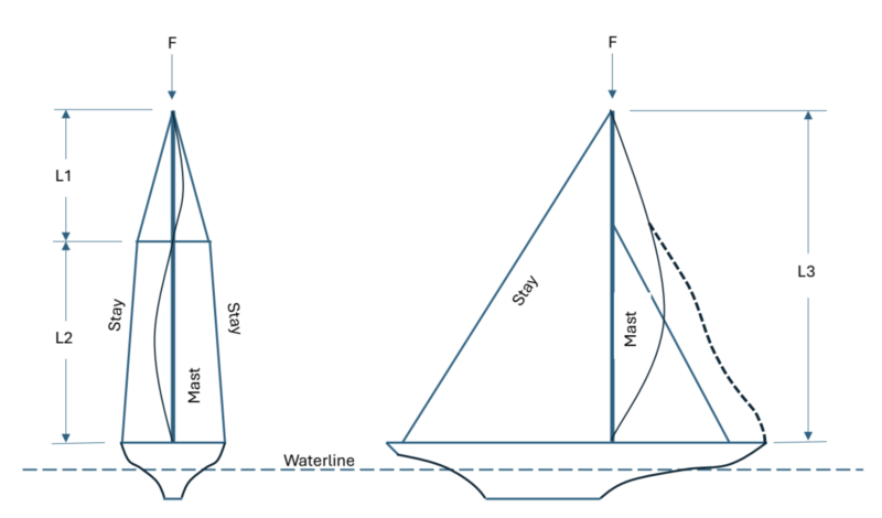
Most of our models have masts supported by stays: sidestays, forestays, and backstays. These stays keep the mast in a straight column. The geometrical constraints of the boat’s relatively narrow beam compared with the tall mast determine how forces are generated and applied to the mast.
The distance from deck to the height of the attachment points of the stays on the mast is much greater than the distance from the base of the mast to the stay attachment points on deck. The wind forces push the mast sideways. This force is resisted by the stays, and we can see this as tension of the stays. This tension is along the axis of the stays—meaning that it runs in the nearly vertical direction of the stays, and so it is primarily a force in the vertical direction. It exerts a downward force: compression on the mast that the mast must be stiff and strong enough to resist.
The key point is that a stayed mast is a slender column that is loaded in compression. Such columns fail by buckling when their “critical load” is exceeded.
Calculating the Critical Buckling Load
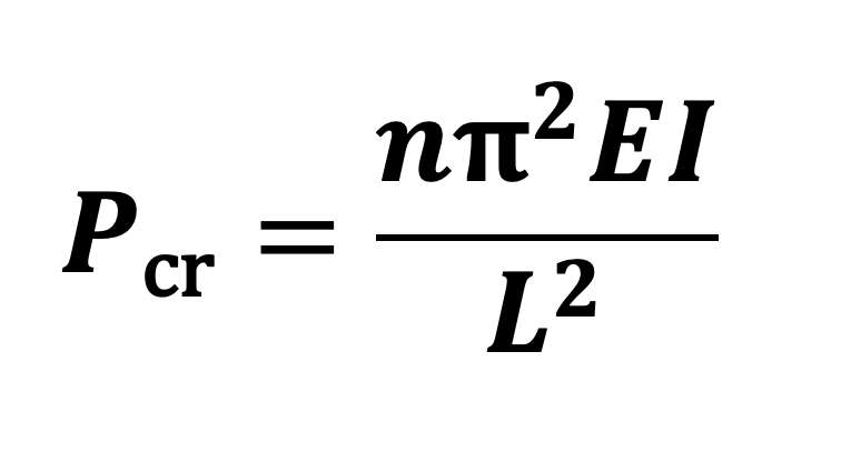
In 1750, a mathematician and theoretical physicist named Leonhard Euler developed a formula for calculating this critical buckling load:
where
Pcr = critical buckling load
n = a factor determined by how the ends of the column are restrained
E = Modulus of Elasticity
I = moment of inertia
L = unbraced length of column
Modulus of Elasticity, E, is a measure of material stiffness or resistance to deformation. Note that stiffness is not the same as breaking strength. Note also that the critical buckling load depends on stiffness, not ultimate strength. This has some consequences for the choice of wood species.
E is a property of the material—the wood species in this case. Tables that give the Modulus of Elasticity for different wood species are available online and are discussed later in this article. Strength is usually associated with density, but stiffness—especially stiffness per weight—may be available with lighter-weight species. This is why spruce is a favored choice for masts in full-size boats. Models can often use even lighter-weight cedar.
The moment of inertia, I, is related to the crosssectional shape of the column and varies as the 4th power of diameter for a solid circular section.
The determination of n in the equation has practical implications for model construction. Usually, our masts are deck-stepped and supported at or near the top by stays. For such a condition, n = 1. Model masts could also be stepped on the keel and supported both at the keel and where they pass through the deck as well as by stays. For this circumstance, where the lower part of the mast is “fixed”, 1 ≤ n ≤ 2. If masts are unstayed, i.e., cantilevered, bending stresses dominate because there are no stays to cause compression or buckling. In these cases, attention must also be paid to the shear forces where the mast passes through the deck and at the step.
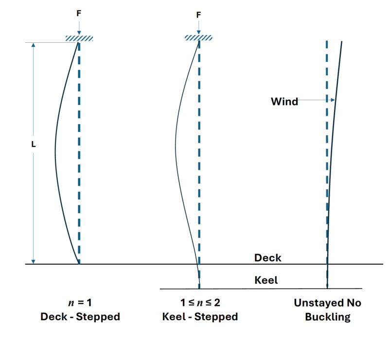
Fig. 1 shows, in schematic and exaggerated form, the buckled mast shapes and values of n associated with these different mast mounting configurations.
Sidestays, including lower stays and spreaders, are “braces” that reduce L and thus enable a larger critical buckling force. This is probably intuitive, but it can be quantified by the above formula. Fig. 2 shows a mast rigged with sidestays, spreaders, a backstay, and a jib stay. The buckling modes—side-to-side and fore-and-aft—are indicated.
This analysis applies to a solid mast and to any practical hollow wooden mast. A hollow mast would be “glued-up”, and the necessary gluing surfaces would make the walls thick enough that any problems associated with thin-walled, hollow-tube columns would not apply.
Detailed calculations for a tapered mast are a bit more complicated; for our modeling purposes an “average” mast diameter should be sufficient. Using the minimum diameter would be more conservative. It is instructive to compare the mechanical properties of some of the wood species that are popular for making model boats. Table 1 lists some example species and gives their Specific Gravity, Modulus of Elasticity, and Modulus of Rupture.
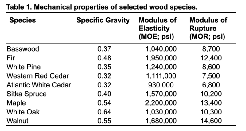
- Specific Gravity is the ratio of the wood species’ density to the density of water—essentially an indication of its weight.
- Modulus of Elasticity (MOE or E) has been defined above and is a measure of stiffness.
- Modulus of Rupture (MOR) is a measure of breaking strength during a bending test.
For mast making, the importance of the Modulus of Elasticity is established by Euler’s equation. Light weight is important for the boat’s stability by reducing weight aloft. Table 1 indicates that western red cedar, white pine, and Sitka spruce are desirable for masts. This assumes, of course, that the sample being used is clear and has straight grain. For those of us without direct access to a sawmill, western red cedar is often the most readily available choice. But wood is not a manufactured material, and the properties of individual pieces piece may vary considerably. The numbers in Table 1 are “typical.” Try to find a lumberyard that allows you to pick through their selection for the lightest, straightest, or clearest pieces.
Calculating Minimum Mast Diameter
Armed with this mechanical engineering knowledge and with the knowledge of wood properties, we can now calculate the required minimum mast diameter for an example model with the following relevant characteristics:
b = half-beam = 0.5 ft (boat beam = 1 ft)
H = Mast height above LWL = 6 f
K = Draft = 1 f
B = Ballast weight = 10 lb
D = Displacement = 16 lb
LWL = 4 ft
Center of Effort (CE) of sail plan = 1/3 of mast height
W = wind force on sails (to be determined)
Allowing for the nice round numbers, this is remarkably similar to a Vintage Marblehead.
Consider first the mast requirements imposed by side-to-side heeling forces (upwind sailing):
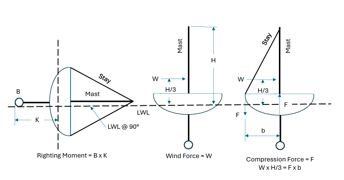
We need to estimate W, the force on the sail. We suggest a simplified approach based on the righting moment of the finand- ballast keel rather trying to calculate the wind force on the sail directly. (Such a calculation would depend on wind speed and projected sail area, which depends on some assumed heel angle, so there would be some messy assumptions.) But the maximum heeling force is determined by the available righting moment, which is determined by the ballast and the draft. When the boat is knocked flat (90-deg heel angle), the wind force on the sails is whatever is required to lift the ballast bulb to the surface. So, in our example, for a model with a 10-lb bulb at the end of a 1-ft fin, the maximum righting torque would be 10 ft-lb—assuming, for simplicity, that the boat rotates about the waterline. (We recognize that this is not strictly true, but it is a reasonable approximation since we do not have lines drawings of the boat.)
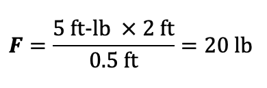
This righting moment is countering exactly the heeling moment generated by the wind on the sails. If, per our example, the sail plan had a peak height of 6 ft, and the center of effort (CE) of the sail plan were ~1/3 of this height (i.e., 2 ft above the LWL), then the force on the sail would be 5 lb at that center of effort in order to generate the same 10 ft-lb of torque as the ballast. We need not specify the actual wind speed or sail area. Instead, we can use these righting moment observations to calculate the force of the wind on the sail. This is one of the key simplifications in our approach.
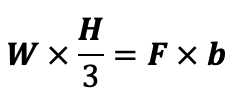
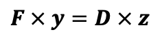
Restating these concepts as an equation for equilibrium, when the righting moment equals the heeling moment,
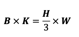
or
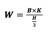
And so the force of the wind on the sail is
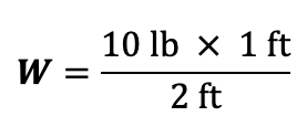
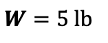
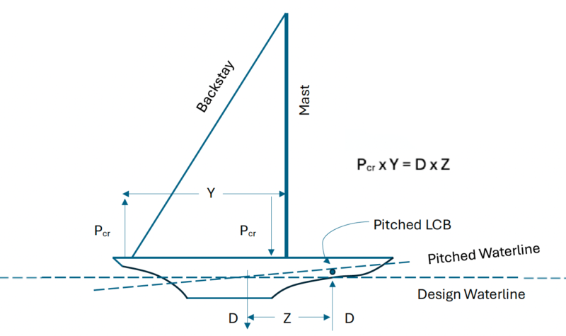
Fig. 3 diagrams the upwind situation, showing a cross-sectional view of the hull. Defining additional symbols that we will use:
F = the force on the base of the mast
z = the distance between the venter of buoyancy (LCB) and the center of gravity (LCG)
y = the distance between the mast and the backstay
d = the minimum mast diameter, which is what we seek
W is a sideways force on the mast, and it causes a heeling moment coupling between the chainplate and H/3. This force pushes the mast sideways, or clockwise rotation in the drawing. To counter this, there must be a force pushing upwards on the base of the mast, rotating it counter-clockwise. This force is F, to be compared with Pcr (critical buckling load) in Euler’s equation.
When the heeling and righting forces are in equilibrium,
Plugging in the data for our example boat,
We now have all the ingredients for Euler’s equation except for the Moment of Inertia, I.
For a solid circular section,
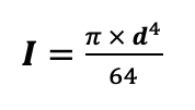
where d is the mast diameter we seek to calculate.
- We will assume a deck-stepped mast, so n = 1.
- We will use western red cedar, with an MOE (or E) of 1,111,000 psi.
- We will assume a single set of spreaders located midway up the mast, and therefore
H/2 is the denominator in Euler’s equation.
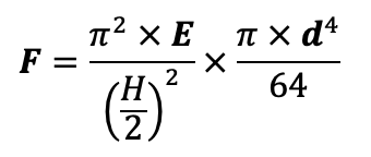
We can use Euler’s equation to solve for d by setting Pcr= F. Note that we should express the mast height, H, in inches to keep the units consistent in the equation below.
Expanding Euler’s equation gives:
Solving for d:
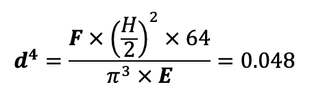
and thus
for the example boat described above with a single pair of side-stays with a single pair of spreaders.
If we compute d for the same boat but braced only by the backstay for buckling in that direction, at L = H, d = 0.66 in. Because the mast has only the backstay to brace it in that direction, the larger computed d (mast diameter) would be required.
Note the necessity to take the 4th root, which requires a scientific calculator, but this is the same as taking two square roots, which most calculators can do.
Caveats:
- There is no safety factor in these calculations, so a slightly larger diameter would be prudent.
- Class rules may require a larger mast diameter. Class rules may also limit the maximum diameter.
- The example computations above were made on a hypothetical boat with dimensions (deliberately) similar to a Vintage Marblehead. The VM class specifies a maximum wooden mast diameter of 0.75 in. The minimum diameters calculated above point to the prudence of using a single pair of spreaders, as most VM modelers do.
Consider now the downwind forces on the mast:
For virtually any practical sloop model, a mast designed per the arithmetic above to withstand the upwind forces will not buckle downwind. The model will pitch-pole before the wind force can break the mast. This assertion will be defended in the sidebar, but this is not necessary reading for determining model mast diameter.
The simple “righting moment” method that we used to estimate the force on the sail for upwind is not applicable in the downwind case. Downwind forces on the sail cause pitch changes (the bow goes down), but there is usually considerable buoyancy forward, and this buoyancy supplements the ballast to resist the pitch changes. Unlike the upwind case, the small pitch angle means that the projected sail area is not much reduced. The boat’s resistance to pitching depends on hull shape—long forward overhangs (think Vintage 10-Raters) provide considerable “reserve” buoyancy to resist pitch changes, whereas boats without much overhang (think Vintage Marbleheads with LWL = LOA) have little reserve buoyancy, and so they “submarine.”
Said more quantitatively, the forces countering downward pitching of the bow result from the coupling torque between the Longitudinal Center of Buoyancy (LCB) and the Center of Gravity (LCG). Plans normally show the location of the LCB (LCB is to flotation what the LCG is to weight). At rest, floating on the designed waterline, the fore-aft positions of LCG and LCB will coincide. However, the LCB will shift forward, possibly dramatically, in response to a downwind gust. (We made a simplifying approximation to ignore the sideways shift of buoyancy in the upwind case because it is smaller for most hull shapes.) We cannot, however, calculate the shifted location of the LCB without lines drawings for the particular boat. So we will approximate.
Fig. 4 diagrams the situation. According to the definitions of symbols listed above and noting that, at equilibrium, the clockwise rotation forces must equal the counter-clockwise stabilizing forces.
or
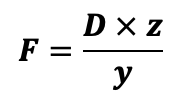
We can derive another expression for F by relating the moments of F and b to the ballast righting moment:
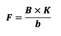
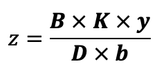
We can perform some algebraic rearrangement of terms to obtain z, the amount by which the LCB will shift forward of the LCG:
Applying the assumed specifications of our example boat from above,
K = 12 in
B/D = 0.6 (i.e., 60% ballast ratio)
b = 6 in
and assume that the mast is 30 in forward of the backstay.
Therefore:
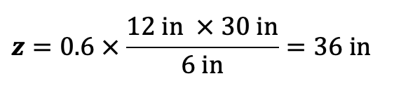
This is the distance that a mast of the strength required for upwind sailing would be able to move the LCB forward without breaking. Note that, in this example, this new position would be forward of the bow, which guarantees a pitch-pole. Therefore, we have shown that the mast strength is capable of surviving wind forces downwind that would overwhelm the boat. The exact values would vary depending on the buoyancy in the bow of the boat, but the general conclusion is sound. This method of analyzing downwind mast requirements is another key simplification in our approach.
The situation for multi-mast boats (e.g., schooners) is somewhat more complicated. The mainmast is farther from the bow, and so more buoyancy is available forward of the mainmast. This means that the boat is less likely to pitch-pole, so the force on the mast could be greater. In the case of schooners, especially gaff-rigged schooners, there is often no permanent backstay. Extra sidestays can perform a “backstay” function, but the compression forces on the mast are increased as the extra stays get closer to the mast. In addition, the mainmast often provides “backstay” support for the foremast with its jibs.
These many variables defy casual analysis. An extra margin of mast diameter is warranted for schooner mainmasts.
References and Sources
- “Euler Column Buckling”: https:// www.engineeringtoolbox.com/eulercolumn- formula-d_1813.html
- “Mast Mechanics: Solid versus Hollow”, Richard Jagels. WoodenBoat magazine, issue #306 (September/October 2025), pp. 88-89.
- Mechanical Properties of Wood: https:// www.fpl.fs.usda.gov/documnts/