
- Title. Author. Summary
- Title. Author. Summary
- Title. Author. Summary
- Title. Author. Summary
- Title. Author. Summary

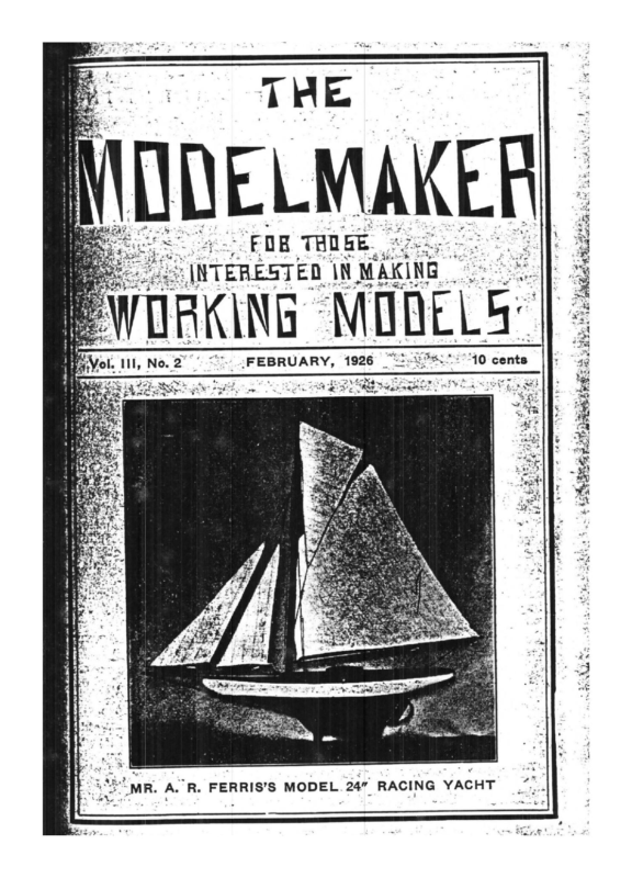
> MR. A. R. FERRIS’S MODEL Bo ‘ a< ° Co) mm aed 10 cents > < oO <= fF
THE MODELMAKER Published by SPON & CHAMBERLAIN 120-122 LIBERTY ST., NEW YORK, N. Y. Issued Every Month : Annual Subscription, $1.00 Copyright by Spon & Chamberlain, February, 1926 Vol. HI. No. 2, “Entered as second-class matter Mar. 27, 1925 at the Post Office at _New York, N. Y. under the Act of- March 3, 1879.” _.- . QUR FOREWORD _ The boiler is, without question, . the most important part of: a- steam power plant, for without its product—steam—the engine - would not function. 4 Much time and scientific’ ex- a’ speed of 300 R. P. M. The water is pumped in at one end and the steam taken out at the other. The tube is kept: about half full of water allowing space for-the steam to generate. centrifugal action of the The tube throws a film of water against the hot tube wall ensuing quick ; ‘-», provement of: the steam boiler, steaming. This boiler has been ..-and in consequence the shapes in successful operation for nea\; and types, and designs, are very .. ly three years producing 700 Ik “y mumerous,” "ii ee eS ~. of steam per sq. in. z “Three of: the most important -; Derimentation has been devoted - to the development and im- ~ “essentials are :Strength and dur - _-production, and low cost The water tube boiler may be cited as one of the most effi' cient type, but it is an expenive piece of apparatus, and if not properly taken care of the cost of upkeep and repairs may be very considerable. One of the most difficult prob- lems for the engineer is the removal of scale from the tubes, for if this is not properly attended to, corrosion may set in and that means leaky tubes with loss of valuable pairs. A Mr. time Atmos, in a making re- Swedish en- gineer, has made a radical inovation in. boiler designs. He has constructed a boiler of a tube about 8 in. dia. and about 11 ft. long. Here is an opportunity for sci- | entific experimentation that should appeal to some of our for . readers. ability, high efficiency in steam This is revolved at As no details’ of construction were given it leaves the Modelmaker free to commence his work from his own particular view point. " The following details would have to be determined tual experiment. by ac- Material—Brass, hard copper or steel tubing. drawn Dimensions—T hickness of wall, diameter, and length of tube. Ends—Form of end pieces. Method of Fixing Ends—Welded, riveted and hard soldered, or threaded and screwed on. It might be advisable to make one end piece to screw on so that the tube could be readily opened an cleaned out.
THE MODELMAKER gre n "20 er
d THE MODELMAKER a MODEL SAIL BOAT a 21 By MR. A. R. FERRIS. ~ The hull of this 24” racing yacht was made by the “Bread wand Butter’ method from 5 white pine boards each of which had Sits corresponding waterline or outline of the shape of the hull at that particular section marked on it from a templet. Each board5 Nas sawed out to its particular outline on a scroll saw. Thebut Faboards were then screwed together one on top of another, outnot glued as yet. The assembled boards, making a rough base ree line of the hull were then mounted on a base board. This a templet paboard had 5 lines drawn across it and for eachat line mhad been made to the correct shape of the hull that particular templet numbered © section. The lines were numbered and eachline. The hull was with the same number as its corresponding then carved out by cutting off the sharp corners of the board and. applying the templets as needed. fic;. When the hull was nearly worked to shape with the gouge it Pewas gone over with a small block plane, wood file and No. 2 sandeach Bepaper. The hull was then dissembled and the inside of y%"”. 2 board sawed out leaving the thickness of the walls approx. BA “4 Hull was then screwed together, LePages glue having been ap“plied to the boards and left to dry for 24 hours. It was then gone over with No. 1 sand paper and then with No. 00. Hull cut was then mounted on a cradle the remaining surplus wood the Be out leaving the walls 3/16” thick. The shear was then cut and inside given two coats of paint. satisThis method of making a hull I have found to be very block. solid a ¥‘Tactory as it requires less work than carving from s ** This is due to the fact that when the sharp corners of the board the to y =‘are cut off, which is readily done, the hull is very nearl a fe it will be when finished. lel The deck was urade from white pine %” thick on which paral to rep.lines were drawn on with a scratch awl and straight edgeribs with two - resent planking. Deck was then nailed on with brads ‘2a slight curve having been fitted in before. being used The rigging is as simple as possible, fish line and rigging hooks and bouses being used to attach the sails. Sails er and *. and masts can be taken down in a few minutes. The rudd E keel are lead weighted.
YLPEASDHMELOapblinoysJapdu ‘£2e/ghl) 22 THE MODELMAKER
8 YSAE IAT 23 THE MODELMAKER makes The model has proved to be a very steady sailer and ns are Model Engineer, principal con- «tents for December 3, 10, 17, 24, “31: Interchangeable Vice-Jaws “for Milling Operations. A 244” #xGauge 4—4—0 Locomotive. Clock Repair work. Making a pair of Standard «Lathe and Treadle. Pad. “Making a Small Drilling Ferrules. Condenser Making The Importance of Modelmaking a5 and Model Engineering. Be ceer ¥i8lide. Control for Locomotive Lathe Bevel Top- Prototypes ¥gs,and Economical Battery-charging A Thermos Stats. Rectifier. ‘s“Model 214” Gauge —4—4J2. -Electrically-driven Tank LocoMotive. Automatic Railway Sig- Cutting Approximate ‘nalling. Selfacting ‘Metric Pitches. ¢<."Brake Mechanism for Lathes. ¥:.- Model Locomotive Building. The 5x Model Battleship “Hopeful.” A : . Portable Dividing Head. Practi‘eal Telephone Installations in A Column of “private houses. 4. “Live Steam” by “L. B. S. C.” Wireless Telephony and Sub- Engineering Light y+. Marine. Ke Equipment and Supplies. Work- i shop Topics. Domestic Engi- Light Electric An ‘* Neering, e Marin Model -;- Supply Failure. Notes. Recent Inventions. A 2” by 2” Horizontal Steam En- gine. Queries and Replies. Practical Letters from Our Readers. Acetylene Welding and the Model Engineer. Reviving Dry Batteries. Society and Club Doings. Titlepage and Index for Volume 53. We understand a Model Yacht Club has recently been organ- in Providence, R. L, and ized, amongst its members are some very skilled model yacht: builders. We wish them every suc- cess. Mr. A. A. Singer recently held another meeting at his office, 15 Moore Street, New York. There were fifteen model enthusiasts present. Mr. Lozier exhibited one of his steam locomotives and some cars which were very much admired. Mr. Singer expects to hold another meeting in February and is in hopes that he willt get sufficient support to warran Engithe formation of a Modelglad to be neers Club. He would reers hear from any of our read siding in New York or vicinity.
70 THE MODELMAKER The “Lightning” on October 31st, 1869, while alongside the pier at Geelong, Australia, with 4,000 bales of wool on board, caught fire from spontaneous combustion and was burned to the water's edge and sank. rT oe ’ 23.25 WL. oper 41 Schock one Sail Plan of Mr. E. I. Schock’s Model Yacht. 1926
THE MODELMAKER 71 A TWO-FOOT WATERLINE MODEL YACHT By E. I. SCHOCK For the beginner at model yacht building and for the man who ishes to have a model that is easily moved from place to place ithout special boxes, I believe a boat of this size and type is very j-line, 9 s<- 5/16 inches beam, 34% inches overall, and has a draft of 9 The hull is built up in the conventional way of boards cut to shape Pen and outside, then glued together. After the glue has set a block of wood is fastened inside the boat, and the model is held ia the vise by means of this block while the outside is shaped. For fethe outside I use the smallest plane I can buy, a Stanley iron plane ‘about 3 inches long. This is a very satisfactory tool, for it is short “enough to slide around the curves of the hull, and can be held in Fone hand. For the cross sections I use cardboard templates. Thin Brood makes better ones if you have it. After it is planed smooth ithe hull may be finished on the inside with a big, long-handled Feauge, outside bevel. For this job I hold the model between pillows to protect the outside. Leave the hull thick in way of Rudder Stock TEI Sand Keel Bolts. The deck beams are carefully notched into the ‘hull, making a little dovetail joint. I do not crown the decks, as a * flat deck saves much labor in fitting, and looks very well on small E models, a Before putting on the deck all fittings must be fastened in place, both on deck and below. &Watertight job. ( The keel clips must be a strong and The vertical rudder stock and tube are very much ‘easier to fit than slantwise ones. I have had one very difficult and trying experience with a sloping rudder, and shall try them no -imore , ‘Deck fittings may be bought from model fitting dealers, or made Rat home. The home made ones are stronger and can be made the Paize you want them. Bought ones are very expensive. 4 The rudder action shown on the Lines Plan is this: fee
72 THE MODELMAKER A double ended tiller is held amidships by a strong elastic and a “runner” such as is used on tents. The line leads through an eye bolt amidships and is fastened to another eye forward. The main sheet is fastened to the aft end of this tiller. This rig is very easily built, and works almost as well as the very complicated ones in use on larger models. The Rudder is a piece of sheet metal, preferably something light. It is riveted to the stock, which in turn is split with a hacksaw to receive the blade. The tiller has a square hole in it, which fits over a square part on the stock. It is held on by a screw fitting into a tapped hole in the rudderstock. By removing this screw the rudder may be unshipped. The fin is held in its clips by small countersunk head bolts. This does not look very rigid, but if the model is lifted out of the water by the hull and handled carefully these will hold. I have this rig on a 39-inch model which has been in use twelve years. It is still strong. The lead bulb on this boat is about 8 lbs. The drawings do not show the lead bulb for the keel. No two builders will get exactly the same weight of hull, so that each keel should be determined by experiment. The rigging on this boat is dark green braided fishing line. All lines have hooks at both ends so that they may be removed easily. The sails are Lonsdale Cambric, finished with Wright’s Bias Tape. The selvage of the material parallels the leach of each sail. d, In making spars the white pine sticks are planed square, taperebe planed octagonal and then round. Spars, hull and deck should scraped before sanding and sandpapered as smooth as possible. To fasten a sail to a.spar stretch a fine enameled radio wire along the spar next to the sail, fastening both ends securely. Lace double the sail to the wire, then fasten the wire to the spar with od this meth you pointed tacks bent from small common pins. By the yacht a more avoid having lacing around the spars, which gives realistic appearance. I have used shellac on decks with perfect results. Valspar var- nish of course is better, but it dries slowly. The hull should have 4 not less than four coats of paint, each coat sanded to make smooth back for the next. The last should be enamel, and left bright. It is not wise to use steel wool in place of sandpaper. It is fast, but scratches. When finished the model is placed in the bath tub for keel experiment. Everything in place. Junk of any kind is piled on deck
73 THE MODELMAKER until she floats on her designed waterline. The weight of the junk is the weight of lead required for the keel. <* The junk is then removed and the model pressed down with a the lead. The Esfinger to get the position of the center of gravity of on her deck in model may be adjusted for trim by pressing down marked. different spots and when the correct trim is found the spotthis point. w ke .The center of gravity of the lead should come just belo her waterline 3? When the model is in the water you cannot see pie tins on the perf om above. To see it from below put some polished u2 & Ships. ae E. e the Rev. W. F .A. Ellison and others, 102 pages, 61 illustra- v=. tions, size 8×5% inches, cloth, ings for small electric motors where these can be purchased, will they kindly send the address to the Modelmaker.
113 THE MODELMAKER MODEL SAIL BOAT “SULMA” BUILT BY MR. ARTHUR R. BROWN Sec. Melrose Highlands Model Yacht Club conform with the maximum size Particulars: block you can get from a given log. It is safe to say that you Length on deck, 36 in. ~.Length of waterline, 26 in. Beam, midships, 634 in. Draft, 71% in. are fairly sure of getting a boat 36 inches long on deck, six and a half to seven inches beam and five inch depth of hull, it is not safe to count on a bulkier boat Weight of lead keel 3 Ibs. Type of hull, dug out. Material, cedar fence post. Sails, Lonsdale cambric. Spars, made of cedar. Deck fittings of brass. Spreaders and mast than this and in fact my exper- fitting pabove deck of aluminum. eIn constructing one of these pueavy models the plans are edrawn up full size on heavy pa- . per. These plans consist of midf8hip section, deck plan and pro- gtle. By cutting accurately to the BS “pld cedar railway ties. I posts at the lumber yard, select- ming those with thick butts and as tree from large knots and checks 288 possible, these posts can be Esbought for less than a dollar in this section and by taking sev- eral at a time they may be peeled, and seasoned so as to have the minimum checks, and by = Duying this way you always have e.Seasoned wood at hand. One post eWill supply material for one mod= el from 36 to 40 inches long and jence is that these approximate dimensions turn out the fastest boat obtainable on this length. Assuming that you have se- lected a good cedar post, the next step is to square it up, this is done by cutting off the re- quired length, allowing about an inch for leeway in laying out. With an ax I hew one side down sufficiently to get the width necessary for my deck pattern, this side is then planed smooth, the two sides are then planed, the bottom is planed enough to get a true centre line. A center line is marked down the top and both ends to meet the centre line on bottom. It is a good plan to mark on the top, lines completely across at two inch intervals at right angles with the centre line. Now that log is smoothed up and marked, take heavy paper deck pattern line it up on top centre lines and mark out deck shape on block, then cut out to shape. Take profile pat- tern and cut out profile shape. . After cutting out profile shape measure down on both sides B enough is generally left from a from top to where bilge start to . ‘good clear log to get out a run to counters by planing from y Smaller boat. bottom down to these lines we -. In building from posts it is jhave our flat floors, counters best to get your cedar squared and runs, it is then only necesUD first and draw your plans to sary to round them up to con-
114 form body. THE MODELMAKER with our plan for underWith a marking guage 1 cut a scarf a quarter of an inch from side of boat full length and hollow out hull to this thickness or less if possible all cver. A false wood keel is made. The pattern for the lead keel : made from wood and split : halves length wise, plaster Paris moulds are made from these pat- terns, the keel moulded, the kee] is fastened with three % inch brass rods, threaded for nuts at both ends, these belts are run threugh hull, false keel and lead
115 THE MODELMAKER : keel, nuts being countersunk into ~lead keel and holes filled with “ lead. The bolts are run through a long aluminum plate in the “hull to prevent pulling through the wood. Inside of hull is given two or three coats of good varnish and deck is put on. I sink all my “decks flush with boat as it 2; makes a neater job. regret to announce the death of Mr. Grover Merriman of the Akron Association of Model Engineers. He was a skilful mechanic, a hard worker and an enthusiastic member of the Association. A man much respect- ed and appreciated by his fellow members, who will greatly miss his kind and sympathetic cooperation in all their work. mst Spars are made of cedar. Deck %:Spreaders and 2 fittings brass. % mast fittings above deck are home are These Br aluminum. We Cal made and can be suited to the – builders own ideas. they also -may be purchased if desired. Sails are cut from Lonsdale Cambric which is very light and es. ee makes a a fine sail. & Mr. J. B. West, of 100 Randall Ave., Syracuse, build a model N. of Y., wants the to American Type Locomotive “999” which we believe was one of the most famous locomotives of its day running on the New York Central Railroad. He would like to a get blueprints and dimensions of this particular locomotive. If any of our readers can supply this information we know that ‘Mr. @& West will very much We had a Dugan, both of them members of the San Francisco Model Power Boat Club. Mr. Willis is an old Railroad man and is naturally more interested in Locomotives, but is broadminded enough to help to support the S. F. M. P. B. C. in the hope that some day this club will grow large enough to include all classes of ModelWe hope that day is makers. Mr. Dugan indistant. far not formed us he has under way a new hull for a Model Speed Power Boat. We understand the members have some very fine We wish Model Power Boats. them a very successful season. ap- preciate the courtesy. The . a 2®>. = very pleasant visit from two of our Western friends, Mr. Clarence M. Willis and Mr. Mr. W. Nelson Rich, 33 Fourth Street, Stamford. Conn., is very much interested in model rail way work. He is planning out a system on a large scale. He a would like to get in touch with . any of our readers interested in %®. this subject residing within a Yreasonable distance of his home. He says he is particularly interested in terminals, signal tems and schedule work. sys- Akron Association now have a permanent meeting place, and in consequence are starting an active campaign to increase their membership. Now is the time to ‘“‘sign on” so that all new members can help in their forthcoming Exhibition of Models. We appeal to all our Ohio readers to help build up this active organ- jzation. Full particulars can be obtained from Mr. J. W. Neptune 130 Paul Court, Akron, Ohio. Please enclose stamped and addressed envelope for reply.