- Title. Author. Summary
- Title. Author. Summary
- Title. Author. Summary
- Title. Author. Summary
- Title. Author. Summary

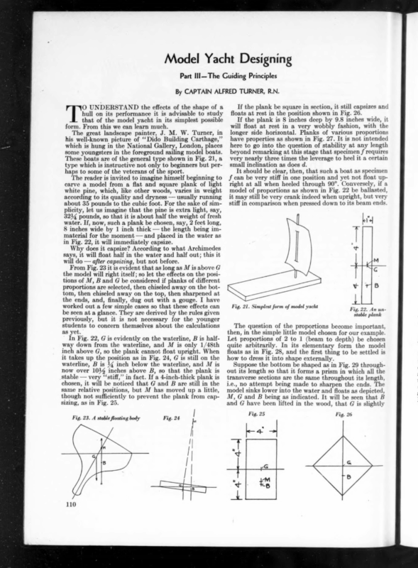
Model Yacht Designing Part IIl—The Guiding Principles By CAPTAIN ALFRED TURNER, R.N. Ts UNDERSTAND the effects of the shape of a hull on its performance it is advisable to study that of the model yacht in its simplest possible form. From this we can learn much. The great landscape painter, J. M. W. Turner, in his well-known picture of ‘Dido Building Carthage,” which is hung in the National Gallery, London, places some youngsters in the foreground sailing model boats. These boats are of the general type shown in Fig. 21, a type which is instructive not only to beginners but perhaps to some of the veterans of the sport. The reader is invited to imagine himself beginning to carve a model from a flat and square plank of light white pine, which, like other woods, varies in weight according to its quality and dryness — usually running about 35 pounds to the cubic foot. For the sake of simplicity, let us imagine that the pine is extra light, say, 3214 pounds, so that it is about half the weight of fresh water. If, now, such a plank be chosen, say, 2 feet long, 8 inches wide by 1 inch thick — the length being immaterial for the moment — and placed in the water as in Fig. 22, it will immediately capsize. Why does it capsize? According to what Archimedes says, it will float half in the water and half out; this it will do — after capsizing, but not before. From Fig. 23 it is evident that as long as M is above G the model will right itself; so let the effects on the positions of M, B and G be considered if planks of different proportions are selected, then chiseled away on the bottom, then chiseled away on the top, then sharpened at the ends, and, finally, dug out with a gouge. I have worked out a few simple cases so that these effects can be seen at a glance. They are derived by the rules given previously, but it is not necessary for the younger students to concern themselves about the calculations as yet. – In Fig. 22, G is evidently on the waterline, B is halfway down from the waterline, and M is only 1/48th inch above G, so the plank cannot float upright. When it takes up the position as in Fig. 24, G is still on the waterline, B is 14 inch below the waterline, and M is now over 101% inches above B, so that the plank is stable — very ‘‘stiff,”’ in fact. If a 4-inch-thick plank is chosen, it will be noticed that G and B are still in the same relative positions, but M has moved upa little, though not sufficiently to prevent the plank from capsizing, as in Fig. 25. Fig. 23. A stablefloating body Fig. 24 If the plank be square in section, it still capsizes and floats at rest in the position shown in Fig. 26. If the plank is 8 inches deep by 9.8 inches wide, it will float at rest in a very wobbly fashion, with the longer side horizontal. Planks of various proportions have properties as shown in Fig. 27. It is not intended here to go into the question of stability at any length beyond remarking at this stage that specimen f requires very nearly three times the leverage to heel it a certain small inclination as does d. It should be clear, then, that such a boat as specimen f can be very stiff in one position and yet not float upright at all when heeled through 90°. Conversely, if a model of proportions as shown in Fig. 22 be ballasted, it may still be very crank indeed when upright, but very stiff in comparison when pressed down to its beam ends. ky T® ~ ! Ke vt Fig. 21. Simplest form of model yacht Fig. 22. An unstable plank The question of the proportions become important, then, in the simple little model chosen for our example. Let proportions of 2 to 1 (beam to depth) be chosen quite arbitrarily. In its elementary form the model floats as in Fig. 28, and the first thing to be settled is how to dress it into shape externally. Suppose the bottom be shaped as in Fig. 29 throughout its length so that it forms a prism in which all the transverse sections are the same throughout its length, i.e., no attempt being made to sharpen the ends. The model sinks lower into the water and floats as depicted, M, G and B being as indicated. It will be seen that B and G have been lifted in the wood, that G is slightly Fig. 26 Fig. 25 I <— 4 af 4 f ‘i | M 110 +18 >
jf F } a oes Lae ke—-5 —sj (@) i 1 |CLe le—c —+ (b) of | H = }-——— 7 ——xi (<) | ee L ) an ap 5 ee ee 2. al s “T Il Le aaa Fig. 28 | I i - 5Bis = oe FS Sl g ) 14 ¥ t . when it falls very rapidly as the waterline plane decreases. Hulls with moderate proportions do not suffer such violent changes in this respect. Can the model be stiffened still more by means of the chisel? Yes. The more the bottom is cut away, as indicated by the dotted lines, the stiffer she becomes. So far, certain effects of chiseling the bottom have been considered, the hull still remaining solid. Can anything else be done to make the hull stiffer? Yes. Some of the tophamper can be removed and a slice (indicated as above pq) can be removed. This brings B up nearer to the waterline, decreases the immersed volume, (volumetric displacement) so that M is higher than ever and G is lowered, and there is an all-round improvement. How far, then, can the upper portion of the wood be J L——. 4" Mag a —“ aaa | Fig. 30 Se : BOX SECTION i ! ! : (e) (J) lower relative to the new waterline, that B is higher than it previously was, and that BM has been increased to such an extent that, although the model is now lighter than it was before in the ratio of 3 to 4, it is actually nearly 24 percent stiffer than it was previously. In this connection it may be remarked that the underwater sections of the well-known schooner America were almost pure triangles amidships. The flat plank as it heels over suffers no noticeable fallin the position of M until the “‘deck”’ enters the water, | J 5 10 (f) o removed? In the completed model it is undesirable that water should get on the deck over the lee rail when heeled at a healthy sailing angle of, say, 30° from the vertical. It means loss of stability and driving power, and the water bursting over the rail constitutes a drag on the speed. It may pour down the hatch, but at present our model has none. The next move is to sharpen the ends for obvious reasons. But what is the effect of doing so? Some of the sections forward and aft then become so narrow in proportion to their depth that the middle of the boat, when she is heeled, may be stable and want to righten, while the ends forward and aft want to capsize. What is to be done, then? Evidently, the ends cannot be left like a square-ended baulk of timber? It is necessary to cut away the forefoot forward and the deadwood aft, so that the ends of the model become of more stable proportions. At this stage never mind theories about wetted surface. Evidently, the model’s stability must be weakened by cutting the ends into points, or more or less streamline entrances, but as a general rule it is advisable to keep the sections forward and aft as full as possible in carving the ends — certainly, it is better for them to be too full than too lean. Hollow entrances are to be avoided except in special cases and, as far as these articles are concerned, they should be avoided altogether. Whatis the next thing to be doneto improve the model? Hollow it out, making the hull as thin as possible. As a general rule this improves the model though it may spoil it as well. The general lightening sends G tumbling down below the waterline, as the bottom may weigh a considerable proportion of the two sides together. At the same time, the volume of displacement becomes small and M may go still further upward. But, on the other hand, two things have happened which have decreased the stiffness. The weight levering the boat upright is very much less and the boat floats so lightly and with such a small waterline plane that she may become unstable when upright. On heeling, however, she puts one side into the water, the waterline plane rapidly increases in breadth, up goes M and the model is stable — not in the upright position, but with a slight list to one side or the other. {mu ej. - p—— tL rr trer ss Hse = om i a ; \ a i t = SE = } J TRIANGULAR SECTION ELLIPTICAL SECTION PEG TOP 111
Plimsoll marks are put on the sides of all British ships. Model yachts, as a rule, follow the general proportions of yachts as far as they are applicable. It is only natural that they should. British yachts emerged from fast merchantmen, fishing boats, smugglers, etc., and for many decades were taxed as regards dues for docking, moorings, wharfage, etc., in accordance with identical rules. In time, as beam was taxed and not draft, the main characteristic of British yachts became that of the “‘ plank on edge,” a type which, as can be seen from the diagrams, is of weak shape whilst upright, yet very powerful when heavily pressed. The Americans, untrammelled in these respects, and with different weather and water conditions, developed craft which were generally more of the light weather, flat bottomed centerboard type. When British yachts were released from the crippling effects of their measurement rules, and external ballast became general, the two types merged to a very large extent. Yet some model yachtsmen still prefer heavily ballasted models with plank on edge features, while others like the lightly ballasted skimming dish model. The former have a big weight at the end of a short lever to keep them upright and the latter a light weight at the end of a long lever. Each has its faults, the latter being very stiff while upright and yet so crank when on its beam ends that, in the case of some centerboard craft, it sometimes turns turtle and floats bottom upwards. Each type is freakish in a sense, and the youngster will be advised to be moderate and design a model of such a shape that its metacenter does not move at all for considerable angles of heel, and stick to the simple elementary principles as briefly indicated, thereby forming a definite, constructive system of shaping the hull. It has been shown that in the case of a solid wooden block a triangular section may be more powerful than a rectangular one of larger size with the boat of heavier weight, but it is unwise to generalize and take it for granted that this is always true. Model yachts are not solid blocks but heavily ballasted hulls of light construction. That the differences between hollow and‘solid models may be appreciated, let it be assumed that it is desired to cut a model from a block of pine 24 inches long by 8 inches wide by 4 inches thick. Any number of different shapes may be cut, but consider only the four elementary shapes as in Fig. 30, in which neither the bows nor the sterns are sharpened or rounded — just boxes — hollowed out to a thickness of 1% inch, and provided with decks of this thickness. For the sake of comparison, load each model down by concentrated ballast suspended by a stiff and light fin, which is so light that its weight may be neglected. Let the four types be spoken of as box section, triangular or V section, elliptical bottom and peg top. The main characteristics of the shapes can be estimated, if desired, by the rules already given — the wood in this case being taken as 36 pounds per cubic foot or 48 cubic inches to the pound. They are given in the following table: — Displacement in lbs. Weight of hulls (Ibs.) Ballast (lbs.) ~ Relative Stiffness upright Relative Stiffness heeled Box 13.9 1.66 V 6.9 1.44 2.3 3.0 1.04 1.6 12.24 (Continued on page 139) ke Fig. 32 LINES OF THE WATER SUPPORT 5.46 yi > Ellipse 10.8 1.52 9.28 1.58 32.7 Peg Top 12.1 1.40 10.70 1 1 Ss bee? 2) C1 Evidently the next thing to do is to ballast the model to bring G down still more so that she can carry sail; as is well known, external ballast is almost invariably used in the form of a lead keel. It is hoped that the reader will realize from these elementary considerations how the French improved the speed of their frigates by sloping the sides of their underbodies inwards as they went downwards from the waterline, and also why the later British tea clippers were given a rise to their floors, in other words, slightly vee’ing their bottoms. If a sailing ship be given proportions, say, 10 of beam to 8 of total depth, she may be perfectly stable with a little heavy ballast at the bottom of the hold, whereas, as she floats so lightly, she may have quite a topheavy appearance. On the other hand, she may be laden deeply in the water with a cargo of grain which fills her holds chock-a-block. She is not topheavy in the ordinary sense of the word, but she may be dangerously unstable if overladen, as the proportion of total beam to total depth is so much reduced. To guard against this, the well-known ae. May, 1931 112
May, 1931 ADYERT’SING PaGrs PrMOVED 139 Yorhting Model Yacht Designing (Continued from page 112) The relative positions of M, B and G are shown in Figs. 30 and 31. It will be noticed at once that the tables have been turned on the triangular sections, the full bodies allowing of greatly increased amounts of ballast and greater stiffness. It will be realized, too, that in the V section with light displacement the weight of the hull becomes a more important factor, as it takes away more than a quarter of the amount of ballast; whereas in the box hull it robs the boat of only one-seventh. On the contrary, the weight of hull is of less importance in the heavy, pudgy models. Any remarks which apply to the weight of the hull apply with even greater force to masts and spars. The effect of sharpening the ends is to lower the position of M because of the reduction in the breadth of the load water plane at the ends. At the same time the displacement is reduced, and the effect of this reduction is to raise the position of M. It has been seen that it is as well to clear away the deadwood, and the effect of this is to raise the position of B at the ends. The net result is that the sharpening of the ends has no marked effect on the position of M — it may be lifted or lowered a little according to circumstances. In this connection, it may be remarked that the position of B is not very far, as regards its vertical position, from the center of the midship section, being generally a little above it. This gives the designer a valuable starting point as he commences his design. The sharpening of the ends reduces the displacement considerably .and, consequently, the stiffness. The proportion of the final weight of the model, after sharpening, to that before sharpening the ends, is termed the prismatic coefficient. It may range from 40 to 60 percent, and it is a handy assistant if used with discretion, but the reader is advised not to attribute any special virtues to any particular value of it. Now the shaping of the ends, in the opinion of the writer, is a matter of first importance in regard to the balance of the model. Yet he realizes that the shaping of the end sections around the lines indicated by the imaginary plumb-bob has been disputed and that the notion of the model resting on the edge of a moving shelf is regarded as fantastic. A study of Fig. 31 shows that the shelf has moved bodily to leeward but, as in these prisms all the sections is likely to _be after heeling, and it is desirable to know this in advance. Models have been designed by the author in which the ends are slightly out of balance and also others, generally similar, with the ends in balance; the diiference in the ease with which each can be handled is very striking, the former being fidgety and the latter most docile and well behaved when sailing. The balancing of the end sections can be carried out in several ways when the imaginary plumb line is known. Full sections or ‘‘V”’ sections or other shapes can be employed. Consider Fig. 33 for a moment. A section sketched in as p g r evidently cannot balance — neither does s¢ u, nor z y z. What is to be done? To retain sections of this type, M must be shifted to the left when s ¢ u begins to become a practical proposition, remembering that a slight decrease in beam brings M tumbling down rapidly, or, in other words, the plumb line moves to the left. This may be undesirable, and in this case the bows may be flared to v ¢ w or beyond, which will make the necessary adjustment. Or it may be desired to use full round sections in the ends in order to balance them; and it should be realized that there is nothing in this method of balancing which makes the designer a slave to either sharp ends or round ends, long overhangs or short. These are determined by the desired length of the boat; and this will be discussed at a later stage. In practice, however, it will be found desirable, in order not to be at the mercy of the’shifting shelf, to place it under control and keep it there by shaping the sections so that it can be nowhere else but where the designer wishes. This is done most readily by shaping the ends so that they balance around the plumb line dropped from the upright metacenter, thereby making the upright and heeled metacenters coincide. (To be continued) are alike, the direction in which the shelf lies is truly parallel with the original center line of the boat and the model does not alter course in the process of heeling. Study for a moment Fig. 32, in which the model is balanced in a rather precarious fashion on the shelf, which is cut along a b c d so that it represents the lines of support under the bottom of the model. As the model heels, the shelf S! H L F moves to the right and the water allows the shape a b c d to alter accordingly and ac- Q. C. f motor cruisers are sold by the following distributors: Albany, New York L. R. Mack, Inc. East of Amityville, L. I. Harold’s Yacht Basin Babylon, Long Island Wayne Frost Boston, Mass. Atlantic Radio and Marine Co. Chicago, Illinois Ward A. Robiasoa commodate itself to the form of the underbody of the model. If, however, the form is such that the new line of support as represented by a b c d lies along a new shelf Cincinnati, Ohio Ohio River Motor Boat Co. Cleveland, Ohio . N.J. Shea Detroit, Michigan Leonard H. Thomson, Inc. Galveston, Texas Robert Sealy Hartford, Connecticut PF. W. Williams, Inc. Huntington, Long Island Chas. A. Gould, 2nd Newark, New Jersey Griggs Sales Company Newport News, Virginia Cc. P. Amory New York, 217 W. 57th St. @ C. f Marine Salon Philadelphia, Pa. Harris, LeRoy & Clark San Francisco, Calif. John G. Rapp Corporation Syracuse, N. Y. Syracuse Motor Marine Corp. Washington, D. C. Stanley H. Horner, Inc. altogether, such as P Q R S?, then the model is wrenched in the direction P Q by the combined action of the lead keel and sails during the process of heeling. If the shape of the bow is too fine, or the quarters are too full a may move to the left and d to the right and the model will gripe. If the bow is too full and the quarters too fine, she will pay off the wind during the process of heeling. The change of direction during the process of heeling has nothing to do with CE’s or CLR’s; and shifting the jib or setting a larger or smaller one will make no difference. _In Fig. 31 it will be seen that the position of the up- right metacenter gives no indication of where the shelf AMERICAN 217 CAR WEST & E&57TH FOUNDRY COMPANY ST.~.-NEW YORK