- Title. Author. Summary
- Title. Author. Summary
- Title. Author. Summary
- Title. Author. Summary
- Title. Author. Summary

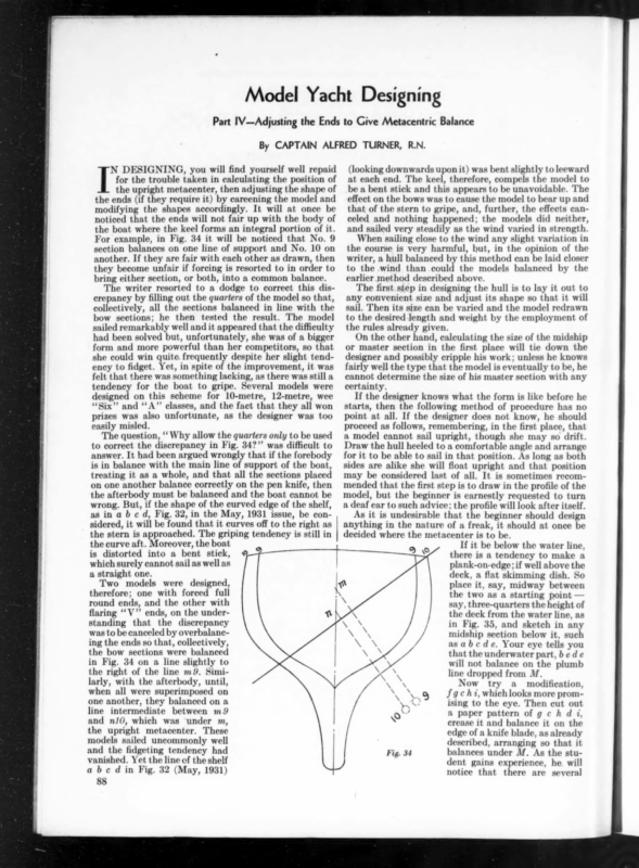
Model Yacht Designing Part I1V—Adjusting the Ends to Give Metacentric Balance By CAPTAIN ALFRED TURNER, R.N. T DESIGNING, you will find yourself well repaid for the trouble taken in calculating the position of the upright metacenter, then adjusting the shape of the ends (if they require it) by careening the model and modifying the shapes accordingly. It will at once be noticed that the ends will not fair up with the body of the boat where the keel forms an integral portion of it. For example, in Fig. 34 it will be noticed that No. 9 section balances on one line of support and No. 10 on another. If they are fair with each other as drawn, then they become unfair if forcing is resorted to in order to bring either section, or both, into a common balance. The writer resorted to a dodge to correct this discrepancy by filling out the quarters of the model so that, collectively, all the sections balanced in line with the bow sections; he then tested the result. The model sailed remarkably well and it appeared that the difficulty had been solved but, unfortunately, she was of a bigger form and more powerful than her competitors, so that she could win quite. frequently despite her slight tendency to fidget. Yet, in spite of the improvement, it was felt that there was something lacking, as there was still a tendency for the boat to gripe. Several models were designed on this scheme for 10-metre, 12-metre, wee ‘““Six’’ and “‘A”’ classes, and the fact that they all won prizes was also unfortunate, as the designer was too easily misled. The question, ‘‘ Why allow the quarters only to be used to correct the discrepancy in Fig. 34?” was difficult to answer. It had been argued wrongly that if the forebody is in balance with the main line of support of the boat, treating it as a whole, and that all the sections placed on one another balance correctly on the pen knife, then the afterbody must be balanced and the boat cannot be wrong. But, if the shape of the curved edge of the shelf, as in a b c d, Fig. 32, in the May, 1931 issue, be considered, it will be found that it curves off to the right as the stern is approached. The griping tendency is still in the curve aft. Moreover, the boat is distorted into a bent stick, $$ which surely cannot sail as well as a straight one. Two models were designed, therefore; one with forced full round ends, and the other with flaring ‘‘V”’ ends, on the understanding that the discrepancy was to be canceled by overbalancing the ends so that, collectively, the bow sections were balanced in Fig. 34 on a line slightly to the right of the line m9. Similarly, with the afterbody, until, when all were superimposed on one another, they balanced on a line intermediate between m9 and n1J0, which was ‘under m, the upright metacenter. These models sailed uncommonly well and the fidgeting tendency had vanished. Yet the line of the shelf abcd in Fig. 32 (May, 1931) 88 ny (looking downwards upon it) was bent slightly to leeward at each end. The keel, therefore, compels the model to -be a bent stick and this appears to be unavoidable. The effect on the bows was to cause the model to bear up and that of the stern to gripe, and, further, the effects canceled and nothing happened; the models did neither, and sailed very steadily as the wind varied in strength. When sailing close to the wind any slight variation in the course is very harmful, but, in the opinion of the writer, a hull balanced by this method can be laid closer to the .wind than could the models balanced by the earlier method described above. The first step in designing the hull is to lay it out to any convenient size and adjust its shape so that it will sail. Then its size can be varied and the model redrawn to the desired length and weight by the employment of the rules already given. On the other hand, calculating the size of the midship or master section in the first place will tie down the designer and possibly cripple his work; unless he knows fairly well the type that the model is eventually to be, he cannot determine the size of his master section with any certainty. If the designer knows what the form is like before he starts, then the following method of procedure has no point at all. If the designer does not know, he should proceed as follows, remembering, in the first place, that a model cannot sail upright, though she may so drift. Draw the hull heeled to a comfortable angle and arrange for it to be able to sail in that position. As long as both sides are alike she will float upright and that position may be considered last of all. It is sometimes recommended that the first step is to draw in the profile of the model, but the beginner is earnestly requested to turn a deaf ear to such advice; the profile will look after itself. As it is undesirable that the beginner should design anything in the nature of a freak, it should at once be decided where the metacenter is to be. 20 If it be below the water line, there is a tendency to make a plank-on-edge; if well above the deck, a flat skimming dish. So place it, say, midway between the two as a starting point — say, three-quarters the height of the deck from the water line, as in Fig. 35, and sketch in any midship section below it, such asabcde. Your eye tells you that the underwater part, b ede will not balance on the plumb line dropped from M. Now try a _ modification, fg ¢ hi, which looks more promising to the eye. Then cut out a paper pattern of g c h d i, crease it and balance it on the edge of a knife blade, as already described, arranging so that it balances under M. As the student gains experience, he. will notice that there are several
Fig. 36 ct shapes which g ch dican take, e.g., Fig. 36, but for the present avoid extremes. As pointed out previously, the ends, 7.e., the shoulders and quarters, should be balanced slightly to the right of the line, and the choice must be made between round and “V” ends. This is a very important matter to decide, and one which should not be settled arbitrarily, as it introduces the question of length. The process of completing the design of the hull may now proceed. A number of calculations will be made, but it is believed that those which are essential have been reduced in number to the bare minimum and to the simplest character. These articles have been written for the benefit of beginners who have had little or no practice in arith- metical calculations, and they no doubt appear verbose to those who have the advantage of mathematical training — the design work being essentially mathematical in character. As far as the latter are concerned, a following method could be described in a few ines. It is a liberal method, inasmuch as it neither ties nor binds the designer to any particular type or size of model. This method, dubbed the “metacentric method” in order to distinguish it from others, has been communi- cated to three different friends of the author, who are unknown to one another, and each has expressed himself as satisfied with the result, after being rather sceptical before getting the hang of it. It is proposed, therefore, to recapitulate and take the beginner through the process, step by step, quoting the necessary references as they arise. These steps will enable the student to begin a design and carry it through to its termination with nothing but his own initiative to guide him. Nevertheless, if he has never designed a model before, he will find it profitable to analyze — and correct, if required — any existing design that tickles his faney. He will then be able to skip several steps by inking Nos. 9, 10, 11, 12, 13, 14 first and then proceeding with No. 1, having determined a definite position for M in the first place — then Nos. 2, 3, 4, 5, 6, 15, 16, and “0 on to the end. The following are the steps recommended: _ Step J. Sketch a midship section of any desired shape in the heeled position under a metacenter M which is paced about three-quarters the height of the freeboard “00ve the load water line. (At a later stage the beginner can place M anywhere he likes and study the innumerable shapes of hull which can be so designed.) Step II. Trace the section on thin paper, cut it out with scissors, crease it for stiffening purposes, and balance it on a pen knife. Step III. Sketch in the bow section by eye, freehand; making it of ““V” type, full-ended type, or as desired, and overbalance it slightly. Strep IV. Sketch in two or more intermediate sections between the bow and midship section so that they balance by eye and yet appear likely to fair up later. Step V. Carry out a similar process with the stern sections, remembering that the run requires flattening somewhat. Srep VI. Draw the sections in the upright position and fair them by means of diagonals, bilge curve, and water lines, the diagonals, etc., being drawn with a batten and all sections freehand. Strep VII. Sketch in the profile of the fin as required. Strep VIII. Check one or two sections forward and one or two aft (subsequent to this first fairing) for balancing, and correct any discrepancies, repeating the above process as required. Make the following calculations with the model in the upright position unless otherwise stated. Step IX. Calculate the area of each immersed half section (Figs. 4 and 5 in the March, 1931, issue). Step X. Plot the longitudinal displacement curve (Fig. 6 in the March, 1931, issue). Strep XI. Calculate the displacement in cubic inches and in pounds. Step XII. Calculate the area of each half water line and plot the vertical displacement curve (Fig. 7 in the March, 1931, issue). Strep XIII. Trace and cut out patterns of the longitudinal and vertical displacement curves and balance them to find the fore and aft and vertical positions of the center of buoyancy. Step XIV. Calculate the height of the metacenter above C.B. If M, thus found, coincides with the position chosen in Step I, the model is, to a large extent, already balanced, but, if not, redraw the sections so far obtained on another sheet of paper, balancing them midway between the chosen and calculated position of the metacenter. Repeat the process, seeing that the general character of the sections is not changed more than necessary. 89
= June, 1931 Yachting If the model be compressed too much by shortening, Srep XV. After correcting all sections, fair them up, remembering that each fairing makes the surface, there must come a time when it begins to pitchpole, or particularly that drawn by the novice, smoother every capsize by the bows, on a run. In 4 sharp-ended model time. with tall sails, the author does not care to have the Step XVI. Heel the model as in Fig. 9 (March, 1931), longitudinal metacentric height much less than the and calculate the heeled immersed sections, keeping in length of the L.W.L., and this limits the extent to which mind whether these sections include one side or both – the longitudinal ‘‘concertinaing” can be carried out in practice. sides of the model, and plot the result to a suitable scale for comparison with the upright displacement curve + ++ by means of patterns, as in Fig. 2. Step XVII. Correct any discrepancy by filling out the Have these articles any bearing on yacht design? The sections above the upright load w«ter line forward, author has had no experience in practical yacht design, while fining up the underbody aft if the heeled C.B. is and therefore cannot speak with any degree of cerabaft the upright C.B., or vice versa, as required by the tainty, but there is little doubt that many a successful pen knife balancing. It may be sufficient to swell one racing yacht would make an utterly useless racing section only forward and compress one section aft in model, not so much from the point of view of: size, order that the effect on the new displacement curves stiffness, etc., but from the point of view of shape. can be ascertained without undue bother. Many cases could be quoted of well-built models Step XVIII. Check the balance and fair up once having been reproduced from the lines of crack, full-size more. yachts. But the models will not sail well enough for Step XIX. Draw the profile in the upright position, racing, as the absence of the man at the helm is so sketching in the fin rudder and stern, and check the marked. It would be absurd to suggest, therefore, that a displacement. large reproduction of a model must make a good fullStrep XX. If the design so prepared be called the trial sized racer. Yet, nevertheless, the hulls of several famous design, and if its L.W.L. is l inches and the displacement successful racing yachts do comply with the requireis d pounds, then in order that it may be reproduced ments of these chapters, with a general exception, without disturbing its balance or shape and be n inches which is to be found in the after deadwood and the L.W.L. and f pounds displacement, draw 1-inch squares tendency, in the author’s opinion, to carry the sail plan over the sections, as in Fig. 17, in the April, 1931, issue, farther aft than could be arranged for in the model. and the corresponding sides of the squares in the final On the other hand, it can be asserted with confidence design will be given by our rule for conversion. that yacht hulls which make much of a departure from Stee XXI. Redraw the hull carefully over the new the proportions laid down as essential for the model squares by freehand, and fair up for the last time. She do not appear to be remarkably successful. should be not only of the exact size and weight desired, but beautifully fair as well. , Step XXII. Insert the fore and aft position of the C.B. in the final drawing by estimating it directly from the position in the trial design, the distance from the bow being trial ae L.W_L. L. times the distance it is from the bow in the trial drawing.* Draw new stations and water lines at convenient distances. + ++ Is this method complete? It shows that while the number of shapes can be enormously great, no alteration can be made to the transverse shapes of a completed design in any spot without the necessity of making another alteration elsewhere. For example, if the floors are flattened, the ends must be filled out; vice versa, if ‘the floors are dropped into the fin. Also, if the floors are dropped for a considerable proportion of the length of the boat, as for a long keel, then the ends require sharpening. Further, the scales of the beam and draft cannot be altered independently of one another by vertical or transverse ‘concertinaing’’ without some general modification of the design. As regards the scale of length, the method is not complete, as it allows the design to be ‘‘concertinaed,”’ in or out, in a fore and aft direction without affecting the balance, and this offends one’s notions of common sense. It will probably be found, sooner or later, that there is a definite connection between the positions of the two metacenters — one of which is under the hatch, and the other two-thirds the height of the mast above the deck. *Note: Proportioning and locating sail plan and ballast are, of course, necessary steps in completing a design. They are, however, not essential to an understanding of the principles of the metacentric method and have, therefore, been omitted from these articles. i . eS 1 The Transatlantic Race Fleet (Continued from page 57) loss of speed due to the reduced rig, as Dorade has a very easily-driven hull, and will probably go nearly as fast in light weather with the new rig as with the old. Mistress, the 61-foot Hoyt-designed schooner owned by G. E. Roosevelt, is getting primed for the fray, as is the cutter Skaal, designed by P. L. Rhodes and now owned by R. F. Lawrence. Both these craft made good showings in the Bermuda Race last year, and should be better than ever with the ironing out of any wrinkles which may have developed during a season’s use. Ilex, the British yawl designed by Charles E. Nicholson, and owned by the Royal Engineers, is due to arrive June 20th, and will be rigged immediately and sailed. to Newport, where the finishing touches will be applied. Flex has an enviable reputation abroad, and so has her crew, which is said to be one of the hardest driving outfits ever to sail in an ocean race anywhere. The fleet will start to gather in Newport Harbor shortly after the start of the Cape May Race from New London on June 20th. Officers of the Ida Lewis Yacht Club have offered the use of their clubhouse to the competing crews, and the Narragansett Bay Regatta Association is coéperating with the Race Committee of the Cruising Club of America by making the fullest arrangements for the comfort and convenience of both crews and committee. , A get-together dinner for the crews will be held at the Viking Hotel, Newport, on the evening of July 2nd.