- Title. Author. Summary

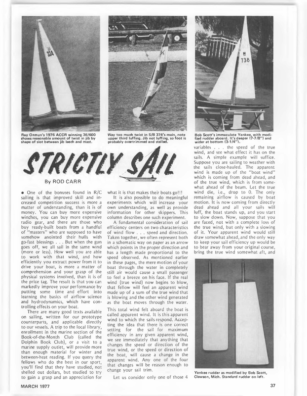
Ray Ozmun’s 1976 ACCR winning 36/600 shows reasonable amount of twist in jib by shape of slot between jib leech and mast. Way too much twist in S/B 374’s main, note upper third luffing. Jib not luffing, so foot is probably overtrimmed and stalled. STRICTLY L By ROD CARR Bob Scott’s immaculate Yankee, with modi- fied rudder aboard. It’s deeper (7-7 /8°”) and wider at bottom (3-1/4’’). variables . . . the speed of the true wind, and see what effect it has on the sails. A simple example will suffice. Suppose you are sailing to weather with the sails close-hauled. The apparent wind is made up of the “boat wind” which is coming from dead ahead, and of the true wind, which is from somewhat ahead of the beam. Let the true @ One of the bonuses found in R/C sailing is that improved skill and increased competition success is more a matter of understanding, than it is of money. You can buy more expensive winches, you can buy more expensive what it is that makes their boats go!!! It is also possible to do meaningful experiments which will increase your own understanding, as well as provide information for other skippers. This column describes one such experiment. radio A fundamental consideration of sail efficiency centers on two characteristics of wind flow . . . speed and direction. Taken together, we often represent both in a schematic way on paper as an arrow which points in the proper direction and gear, and there are those who buy ready-built boats from a handful of ‘masters’ who are supposed to have somehow anointed their hulls with go-fast blessings . . But when the gun goes off, we all sail in the same wind (more or less). How well you are able to work with that wind, and how efficiently you extract power from it to drive your boat, is more a matter of comprehension and your grasp of the physical systems involved, than it is of the price tag. The result is that you can markedly improve your performance by putting some time and effort into learning the basics of airflow science and hydrodynamics, which have controlling effects on your boat. There are many good texts available on sailing, written for our prototype counterparts, and applicable directly to our vessels. A trip to the local library, enrollment in the marine section of the Book-of-the-Month Club (called the Dolphin Book Club), or a visit to a marine supply outlet, will provide more than enough material for winter and between-heat reading. If you query the fellows who do the best in our sport, you’ll find that they have studied, not shelled out dollars, but studied to try to gain a grasp and an appreciation for MARCH 1977 has a length made proportional to the wind die, i.e., drop to 0. The only remaining airflow is caused by boat motion. It is now coming from directly dead ahead and all your sails will luff, the boat stands up, and you start to slow down. Now, suppose that you are faced, not with a complete loss of the true wind, but only with a slowing of it. Your apparent wind would still draw somewhat ahead, and the only way to keep your sail efficiency up would be to bear away from your original course, bring the true wind somewhat aft, and speed observed. As mentioned earlier in these pages, the mere motion of your boat through the water in completely still air would cause a small passenger to feel a breeze on his face. If the real wind (true wind) now begins to blow, that fellow will feel an apparent wind made up of a sum of the true wind that is blowing and the other wind generated as the boat moves through the water, This total wind felt aboard the boat is called apparent wind. It is this apparent wind to which the sails respond. Accepting the idea that there is one correct setting for the sail for maximum efficiency in any given apparent wind, we see immediately that anything that changes the speed or direction of the true wind, or the speed or direction of the boat, will cause a change in the apparent wind. Any one of the four that changes will be reason enough to change your sail trim. Let us consider only one of those 4 Yankee rudder as modified by Bob Scott, Clawson, Mich. Standard rudder on left. 37
; TO 2X2 MAST 7.’ ‘ a / Oe 4 / / 1 MILE & oe 1 / / oe – S| ;/ x= A fill your sails. What we have discovered here is that a change in the speed of the true wind will require either a change in the boat’s heading, or a change in the angle of attack of the sails. We have all spent a lot of time trying to remove twist from our sails, I’ve written a good deal about vangs and travelers and how they can be rigged to do just that. But what if there is a change in wind speed as one goes from the deck of the boat to the masthead, in other words, change in velocity at various levels above the water surface. Common sense tells us that at 40 or 50 feet aloft, the speed of the true to its “free stream velocity”, i.e., it is not affected by the water surface in open areas. It also seems reasonable to assume that the true wind right down next to the water must be almost zero. The air molecules intimately in contact with the water surface might have a speed related to any water current that was flowing, but in our recent discussion of heavy-air sailing, we found out that the surface water flows first forward, and then backward, as waves pass. So that considering air motion to be nearly zero at the surface is a pretty good approximation. Now we have two points on some kind of a curve, zero wind speed next to the surface, and some kind of unaltered ‘free stream” speed aloft at 40 to 50 feet. Some kind of wind blows between these two levels, and the simplest expectation is that there is an increase in wind speed with altitude, A mathematician would call this a velocity gradient. Go up the mast a few feet and the wind is blowing harder. In a preceding paragraph, we convinced ourselves that a change in the speed of the true wind was going to require a change in trim of a sail which had been working at maximum efficiency. Acommon sense kind of analysis of the actual structure of the true wind convinces us that there is some kind of a gradient of wind speed as one goes up from the water. The inescapable conclusion is that different parts of the 38 LAKE ACCOTINK if GUY / hope that the new apparent wind would is something close / I aoe H MEASURED DISTANCE TO GROUND wind FIG. 2 ae, / Y / es KNOTS WIRES oh un A sail are going to have to be trimmed differently if we want them to work at peak efficiency (I promise to look at the efficiency problem in detail in a future column). You are now at a point in your understanding that | reached in 1970. Being a lazy fellow, | never went any further, until | started wondering if having the top quarter of my main leech fluttering while going to weather was indicative of a power loss. Experiments with leech tension proved helpful, and I finally started beating the bushes for some hard information on the true wind and its variation with height. Scholarly papers from Dr. Keith Ruggles and Dr. Erik Mollo-Christensen of MIT, and Dr. P.A. Sheppard of Imperial College of Science and Technology in London, were obtained. In both cases, the information presented did not extend near enough to the water surface to be helpful, and the data taken was not closely spaced either. Recently, SAIL Magazine published an article by Richard Hirsch which began to get closer to our needs. He moored a catamaran in open water and spaced anemometers up its mast from 6 to 38 feet above the water. He ran ail their cables to read-out dials clustered in a box and rigged a camera to take pictures of all the dials at once, obtaining an instantaneous reading of the velocity profile. His conclusion was that the velocity at 6 feet was typically 8090% of the free-stream velocity, considered to be at 38 feet. He worked in wing ranges from 5 to 25 knots, and observed a similar distribution throughout the whole range. Other than these references, information for below 6 feet, in 1 or 2 foot increments, just didn’t exist. And if we believe Mr. Hirsch, there must be a change from 0 to 6 that is 80-90% of the change observed all the way up to 38 feet. In only 6 feet of altitude, this says that the gradient is steep, and may be variable in form as the free stream Well, there was no other way to find out but to do it ourselves. So we set to work to provide the instrumentation we needed. In Figure 1 you will see the Mark | King Kong Ping-Pong Anemometer! A ping-pong ball was suspended by a thread from the center of a quadrant. The harder the wind blows, the greater the thread angle on the protracter. A cleat was provided on the 1/2 inch maple support dowel to allow adjustment of the length of the string. The dowel was a force fit in a 7 foot length of 2×2, which allowed it to be twisted enough to assure that the ball and thread were hanging free. As an exercise, | derived a calibration curve of angle versus wind speed, using a drag coefficient for a hemisphere found in Curry’s 1924 book. Actual calibration was carried out from a jury rig hanging out the window of my 1965 vintage Mustang. The two curves differed only by a factor of two, and probably reflected a drag contribution from the thread that [ had tgnored in my analysis. The whole apparatus was assembled as shown in Figure 2, and with the help of Bob Harris, was anchored upwind from a 1.5 foot high peninsula in the middle of Lake Accotink, in Spring- field, Virginia (Fig. 3). Shown along with the apparatus in Figure 2 is the resulting a FIG. 1 aut rreoe reer WIND / velocity changes. MODEL BUILDER
profile that one can plot after reading the angle from each protractor, converting it to wind speed, and plotting it on graph paper. As installed, the top meter was just about 7 feet above the water. | used a 135mm lens on my camera and shot a whole roll of film of this 7 foot elevation. Na) contraption on a day when maximum wind speed was about 17 knots at the Each picture is an instantaneous measurement of the speed at each level. A number of things should be mentioned as having possibilities for biasing the results. (1) We have assumed only hori- zontal wind movement in our analysis. If there is vertical movement caused by turbulence, it could conceivably buoy up the bali giving a false measurement. (2) If a picture was taken after a puff, some of the balls may be swinging (3) 2 mph BOAT SPEED WIND pressure as we specified. Indeed, a few of the shots show higher wind speeds at lower levels, indicating some cases of such a pertubation. 2 mph BOAT SPEED WIND rather than leaning up against the wind The lowest indicator was only 2 inches off the water, and as small wavelets passed, they had the effect of squeezing air upward under the ball, giving a buoyancy effect as mentioned in No. 1. As a results, some of the readings given by this indicator are anomalous. In Curry’s book, he mentions the idea that there is actually an overall upward inclination of air movement FIG. 5 near the surface and he picks 4° as a likely angle. | don’t know whether he is talking about packets of air richocheting off the water surface or what, but our lowest ping pong ball certainly did do some odd dancing. (4) All of the above sum up to say that what we want to extract from the photos is some sort of a weighted average behavior, rather than trying to make up a complete story for each frame. The profiles in Figure 4 are illustrative. Note that the data from the bottom indicator has been plotted, but only in the case of profiles A and C does it seem to fit the pattern of the rest of the profile. Profile A is the situation that | think exists just after the arrival of a puff. The air near the water is still, since the energy of the puff is working its way downward, chewing up the 1 to 2 foot thick boundary layer. Profiles B, D and E could be considered later stages in the process, with profile C being the final situation just after the puff has started to’ die out. If we consider the freestream velocity to have been about 16.25 mph at 38 feet, then 80% of that is the 13 mph we observe at 7 feet in profile E. But assuming that there was a time between E and C when the 7 foot speed was 13 mph, we see that the 8 knots established at the lowest point on profile C is over half of the freeMARCH 1977 stream velocity. Now let us consider the difference in velocity between the 1 foot level and the 7 foot level. This is a good approximation of the foot and head altitudes of an EC/12, Newport 12 or most Marbleheads. Averages observed in profiles A, B, D and E show that at 1 foot, the speed is 5.5 mph, while at 7 feet, it is about 10. At either extreme in the profiles, this 50% ratio is a pretty good approximation. What kind of an effect will this have on sail trim? First of all, let us assume that the angle between the apparent wind and the chord of the sail must be 30° for maximum efficiency. This is way off base, but will get the message across, and is much easier to diagram. Figure 5 shows the angle, the chord and the means for getting the apparent wind, at the foot of the sail. Boat speed is 2.0 mph, true wind we will let be the 5.5 mph average from above. The angle between the centerline of the boat and the chord of the foot of the sail is shown as 5.28°, and the angle between that chord and the apparent wind as 30°. Notice that the apparent wind is larger (7 mph) than the true wind speed or the boat speed. Also notice that the apparent wind appears to come from a direction nearer the bow than the true wind as a consequence of the boat speed wind. The angle between the centerline of the boat and the apparent wind is 35.129. If we now go up to the mast head, the true wind has increased to 10 mph as a consequence of the wind gradient that we have measured. In Figure 6, the faster true wind speed of 10 mph is plotted. The apparent wind now grows to 11.5 mph and draws aft to an angle of 40.28° from the centerline of the boat. To maintain the specified angle of 30° with the chord of the sail, the angle the chord makes with the centerline has to be increased to 10.289. For the sake of comparison, the previous foot chord from figure 5 has been drawn in. Continued on page 107 39
tion and adjustment are both simple. A drop of only 300 to 400 rpm at the high end is claimed, and long periods of idle are possible with no engine overheating. Priced at $16.95, and guaranteed for one year, the unit can be used without the muffler, as a throttle only. They are on the way to your local hobby dealer, or order direct from Hiscott Components, 2910 Peppertree Lane, Unit C, Costa Mesa, CA 92626. * * ‘(COMPLETE \ x», R/C YACHT KITS With our modern, engineered system of stainless steel deck and sail rig hardware and extruded aluminum spars. And with Vortex-made sails FROM $358 and fiberglass parts of a TO $395 just not available anywhere precision and finish that is else. * Approximately 330 carefully Neither the English ‘‘Aeromodeller” nor Ron Moulton, it’s Managing Editor, organized items in each kit. should need much introduction. And neither should their ‘Aeromodeller Annual’, the 1976-77 version of which Sixty-page, step-by-step assembly manual includes complete control equipment has just been released. installation drawings for two This year’s 5-3/8 x 8-1/2, 144 page version covers everything from A-frame rubber designs to compressed-air driven scale models, R/C, and even an R/C Vortex SC-3 sail control unit. model airship. mation Articles excerpted 12 nations naturally. or three channel radio and Mail ordes only and information have been from model publications of .. . Model Builder included, Interestingly enough, a glos- Write for FORTE sary of aviation/model terms is inclu- Cy J ” eer ded, for the reader of Polish, English, Russian and German publications. Must reading for all serious modelers, the book is priced at 2.25 English pounds; our local bank gave us the latest exchange rate of $1.7475 to the pound. For more information, and US prices and shipping costs, inquire to Publicity Dept., Argus Books, Ltd., Argus House, 14 St. James Rd., Watford, Herts. Merrie Olde Englande, naturally. * ak * A most innovative answer to the prop balancing problem has become available recently. Known as the “Bubble Balancer”, it is designed to accommo- date props with 3/16, 1/4, and 9/32 inch prop holes, and is claimed to take all the guess-work out of balancing propellers. Constructed entirely of metal, using a super sensitive level, the Bubble Balancer has hardened frictionless pivot points and surfaces. It can be used to balance props with any number of blades, in all directions. The Bubble Balancer is priced at $12.95, plus $1.50 for postage and handling. Sleeves for 5/16, 3/8, and special size prop holes are available for $1.50. Order direct from Howard Huebl, Box 193 Route 4, Mankato, MN 56001. * * Milman Engineering Co., Inc. 3448 Bishop Rd., Chehalis, WA 98532, announces the availability of spoked wheels for scale and standoff scale models in sizes from 2-3/8 to 5 inches. The tires are molded of Buna rubber, either smooth or treaded. The rims and spokes are nickel plated stcel, and nylon bushings are installed in 1/8 or 5/32 inch |.D., depending on wheel diameter. Tire widths vary from 3/8 to 3/4 inch, and MARCH 1977 East Ortega santa Barbara, Street CA 93101 weights from 3 to 10 ounces, all based on diameters. Write direct to Milman Engineering for complete information including prices. Tell them MB sent you. @ Sailing…… Continued from page 39 From this exercise we conclude that complete removal of twist from a sail will be detrimental, and all other things being properly adjusted, we should allow about 5° twist in a sail with a 65 to 75 inch luff. If a sail foot is significantly closer to the water as it is on some of the 36/600’s, it might be necessary to reassess the situation, since our Figure 4 shows the steepness of the gradient to be greater nearer the water, and hence percentage change in true wind speed will be greater. All the previous comments | have made about tight leaches, and leaches which are overtrimmed, still hold. Also, the 5.12° boom angle is not real. ft will be significantly different for different boats, for different sai! cuts, and so on. What is real is the 5°+ of twist that should be allowed for in the sail as one goes up the mast. Where do we go from here? A couple of further projects suggest themselves. The first is to use a video tape set-up to film the action of the indicator pole. Since the tape can be played back in 1-second stop action we could build a series of 1-second profiles. By con- = £ as : ial —_— David Mainwaring necting the dots with a smoothed curve and then putting the profiles themselves back on video tape one could make a movie of the actual arrival of a puff. | think that there would be ample proof of a theory | have on why many models when hit by a puff, first heel, then slow down, and finally all of a sudden round up, luffing head to wind. Believe me, you’ll read about it right here in Model Builder if we manage to complete the task. A second use for this data is going to be in the calculation of power distributions and heeling moments for those classes which have changeable sail plans. It also may make some meaningful contributions to the design WHEN CONTACTING ADVERTISERS, TELL ‘EM MODEL BUILDER SENT YOU! 107
( Bh $ ESPECIAL TIES Now ta after three years of testing and development, a precision die cast aluminum Safety Shear Rudder Blade Assembly for .40 and .60 class boats. SS Rudder Assembly complete ……. $12.95 includes: Safety Shear Rudder Blade, Shear Pin, Shear Pin Retainer, Controi Arm, Pivot Pin, Pivot Bracket, Mounting Plate, extra Shear Pins and extra Shear Pin Retainers. All seven component parts can be purchased separately. SS Rudder Blade only Oe > oi $7.95 IMPACT = oy CATALOG $1.00 FULLY GUARANTEED “FORMULA“VEE” : = @ FIRST IN SOUTH AFRICAN WORLD CHAMP IONSHUS @ A WINNER FOR Your @ RIT INCLUDES NSTALLEQ ONE TAY OVER 80 LiPr © SUPER HANDLING HAND LAMINATED FIBFAGLAS HULL A DFCK, MOTOR AILS POCTUAE PLANS”, COMPLETE MLL DING & RUNNING INSTRUCT (ONE, FRANSOM SLOPOAT iNSTALLEO SCOMPLETE HARDWARE KIT: EAT TREATEO FLEX Calf OM1VE, STAINLESS AULODER STAUT. AMD AIDE OL ATES: STAINLESS STEEL TUAN Fit, HUTS 4 OO: 7S AESDLE FARING RUDOFR & STRUT BMD Mid POSTAGE & HASO1 200 £08 COMPLET) ie? Ome THO WARDCRAFT MARINE *6 bOx MY CYNARFOOO, WASH pO0t8 Phone 1708) Tri Ieee of storm sails for the one-designs such as the EC/12, which has such a bad time in heavy air. All in all, it seems to have been worth the effort. It has really just opened the door on an area of basic aerodynamic research that will pay off for model yachtsmen in improved performance, for which the only charge is to scratch your head and dig in to it. Remember to send your AMYA dues of $5.00 to the Secretary, 2709 So. Federal Highway, Delray Beach, Fla. 33444. And I’ll field questions accompanied by a self-addressed, stamped envelope to Rod Carr, 7608 Gresham St., Springfield, VA 22151. e Remotely …. Continued from page 19 between the weigh much, pieces, and that doesn’t “Engines for C/S won’t be a problem so far as power requirements are concerned, but unless geared, few will be able to swing a scale sized propeller. A good .45 should handle most lightplane configurations . . . though a .60 or better will be required for higher 108 DEALER INQUIRES INVITED horsepower prototypes, and if converted to ignition, should be able to turn a larger, near-scale prop and still offer a good rpm range. Brute force is neither required nor desired. Few, if any, full Frank Ward presents! @AHAMEA RECORD HOLDER may be used in Marine Specialties HBR and 2/3AR Rudder Assemblies. size J-3’s offer STOL takeoff performance, so why shoulda 1/4 scale model? “Aerobatics, for those so inclined, needn’t depend upon brute force either, Unlike the average R/C pattern or cven sport model, C/S should fly realistically. P.O. BOX 588 SARATOGA, CA 95070 that can provide all the control a pilot can use …and often times, more… the slow flight speeds and low mass of C/S models should relegate most mishaps to just that . . . minor accidents. The concept demands that flying be accomplished in near ideal conditions. Certainly, very little wind can be tolerated. Any breeze more than about 8 or 10 mph could be hazardous. “Materials of construction for the airframe could well become something Only very specialized, extremely high power/weight ratio full scale airplanes can even approach the full power maneuvers of models . . . such as vertical climbs from level flight. The C/S aerobatic pilot should plan a nose low, speed other than ‘automatic balsa’. Spruce, bass and pine could be most useful and economical, as could expanded bead build-up entry into loops, rofls and other velocity-dependent maneuvers. Only makes sense. And, oh boy, just listen to 8-foot span biplane could rival the tooling and setup charges for Ford’s Pinto. them wires whistle. Whoooece! “Cylinder heads for phoney radial or other exposed engines will require some skill and ingenuity, but with the casting and expanded-foam plastics now commonly available, these can be formed by most hobbyists with a bit of guidance and patience. Special size and contour spinners will be a bit tricky. Okey. So be it. Propellers . . . true scale diameter and shape . . . might be reserved for static display, They’ll undoubtedly be hand-whittled and seldom used for flight. Remember, at 1/4 scale, many will be 18 inch diameter and bigger. “There’s tittle doubt but that C/S will put some real building back into modeling. Unless a person decides to go the very limited kit or plans route, it’s going to be a design and scratchbuild activity. And why not? That’s fun, too. And talk about pride of ownership! Should give the magazines a chance to publish some unique new designs and ‘how to” material. “C/S model longevity should be excellent. With radio systems available foam block and sheet. The cost of sheet balsa wing ribs for a 15-inch chord, Foam sheet with balsa cap strips might save a veneer, weck’s wages. aluminum Certainly, thin sheet or even card stock overlayed with a light fiberglass laminate could find many uses. Interplane struts can utilize aluminum tubing… not necessarily the sizes and grades available at hobby counters… streamlined with balsa trailing edges and wrapped with cloth tape. Flying and landing wires of small diameter, braided flexible wire . . . as in U-control .. . might terminate in miniature turnbuckles such as offered by Lou Proctor Enterprises. ‘’So that’s some of the basic thinking, problems and potential for C/S aircraft models. Now, what the hell do we do with them? “Most important is ‘have fun’. This could range from static display and one- atta-time fly-by demonstrations at picnictype affairs, to competitive, free-style aerobatics, spot landing events, slow flight demonstrations, short-field and obstacle take-off and landing contests . the whole she-bang. Again, ‘fun’ has got to be the rule . .. or rather, the WHEN CONTACTING ADVERTISERS, TELL ‘EM MODEL BUILDER SENT YOU! MODEL BUILDER