- Title. Author. Summary

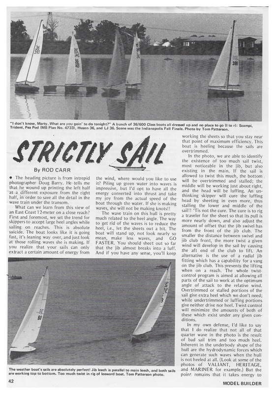
ic a GST eR “| don’t know, Marty. What are you goin’ to do tonight?” A bunch of 36/600 Class boats all dressed up and no place to go (I to r): Scampi, Trident, Pea Pod (MB Pian No. 4733), Huson 36, and LJ 3 6. Scene was the Indianapolis Fall Finale. Photo by Tom Patterson. RITE By ROD CARR @ The heading picture is from intrepid photographer Doug Barry. He–tells me that he wound up printing the left half at a different exposure from the right half, in order to save all the detail in the wave train under the transom. What can we learn from this view of an East Coast 12-meter on a close reach? First and foremost, we set the trend for skippers to accept large heel angles while sailing on reaches. This is absolute suicide. The boat looks like it is going fast, it’s leaning way over, and just look at those rolling waves she is making. If you realize. that your sails can only extract a certain amount of energy from working the sheetso s that you stay near that point of maximum efficiency. This boat is heeling because the sails are overtrimmed. In the photo, we are able to identify the existence of too much sail twist, most noticeable in the jib, but also existing in the main.. If the sail is allowed to twist this much, the bottom . the wind, where would you like to use will be overtrimmed and stalled; the it? Piling up green water into waves is middle will be working just about right, impressive, but I’d opt to have all the and the head will be luffing. An unenergy converted into thrust and take thinking skipper will cure the luffing my joy from the actual speed of the: head by sheeting in even more, thus boat through the water. If she is making Stalling the lower and middle of the waves, she will not be making knots!! sail!! ‘Tis not the cure. The cure is to rig The wave train on this hull is pretty a traveler for the sheet so that its pull is much related to the heel angle. The way more nearly down, and also adjust the to get rid of the waves is to reduce the amount of offset that the jib swivel has heel, i.e., let the sheets out a bit. The from the front of the jib club. The boat will stand up, not look nearly so smaller the distance between swivel and mean, make less waves, and GO jib club front, the more twist a given FASTER. You should: sheet out so far wind will develop in the sail by causing that the jib almost breaks into a luff. the aft end of the club to lift. An And if you have any sense, you’ll keep alternative is the use of a radial jib fitting which has a capability for a vang on the jib club. This prevents the lifting when on a reach. The whole twistcontrol program is aimed at allowing all parts of the sail to work at the optimum angle of attack to the relative wind. Overtrimmed or stalled portions of the sail give extra heel which we don’t need; while undertrimmed or luffing portions give neither drive nor heel. Twist control will minimize the amounts of both of these which exist under any given conditions. In my own defense, I’d like to say that | do realize that not all of that quarter wave in the photo is the result of bad sail trim and too much heel. Inherent in the underbody shape of the hull are the hydrodynamic forces which can generate such waves when the hull is not heeled at all. (Look at some of the The weather boat’s sails are absolutely perfect! Jib leech is parallel to main leech, and both sails are working top to bottom. Too much twist in rig of leeward boat. Tom Patterson photo. 42 photos of VALIANT, HERITAGE, and MARINER for example.) But the point remains that it takes energy to ‘ MODEL BUILDER
make that water pile up, and that energy has got to come from the sails, thereby subtracting from the useful amount of power that can be utilized to drive the boat. As | understand it, part of this quarter wave is associated with the water breaking away from the hull surface. If one fattens his hull farther aft, the water has a tendency to remain “attached” to the hull. In part, this is the reasoning behind moving the maximum beam location farther aft on a boat. In the East Coast 12-meter class, the original class rules specified the maximum beam on deck, but not its location. In the past 5 years, the maximum beam location has crept aft from about 32 to to 34 inches to the 36 to 38 inch area. A lot of this sheer beam measurement has undoubtedly been reflected in a fattening of the underbody_ below it. As a result, the newer, slimmer hulls may be providing a somewhat reduced quarter wave. But before you all jump into the arena and start chopping, remember that the class rules forbids modifying a hull. A new set of motions put out by the technical committee will once and evolution was done MASTS There forever put a stop to further in this class… High time it too. are a lot of misconceptions| floating round about that tall stick that sits in the middle of your boat, holding up the mains’! with all kinds of wires running to and from it (Now you’re using terms | can understand! wen) Some of them (both masts and misconceptions) can be a direct cause of poor boat performance. Often, a bad mast is the result of taking one facet of boat performance to an extreme, to the detriment of other facets. The most serious example is the continual hollering for light masts. This is not the primary requirement of a mast… The primary requirement of a good mast is straightness and ability to accept a regular, controlled bend. The good sailmakers urge you to start with a straight mast as you prepare to tune your boat. They don’t mean that you have been able to pull the bows, hooks, and kinks out of that “dog leg’ with all sorts of un- balanced shroud tensions. They mean that standing all by itself in the corner, with no stays or fittings, and no pulls or tugs, the mast is straight! EC/12-Meter showing the excessive heeling and huge quarter-wave which developes when sails are overtrimmed. Photo by Doug Barry. find out is if the bend is regular. Runa thread between the head of the mast and a point as near to the heel as you can. Every 3 to 6 inches, measure the difference between mast and reference thread, using a machinist’s rule graduated in 64ths (Figure 2). Make a table of distance from the head versus offsets measured. Plot them on a chunk of graph paper so that the 6 foot mast is 6 inches tall on the paper, and so that 1/32 inch of offset becomes 1/8 inch. You’ll wind up with a very bowed plot which should allow a fair curve to be thrown through it. Possible kinds of non-regular curves are shown in Figure No. 3. Example A is typical of a wooden mast which has had holes drilled in it to FIG. HEEL a take a set of spreaders about 2 feet up — and another hole for the jenny strut about 5 feet up. You can see how this weakens the section and makes the overall shape one of three essentially straight segments with definite angles between them. Imagine how unsatisfactory the match will be between this mast shape and a mains’! which has had a smooth luff round-cut into its leading edge. How to fix this mast… ? Cut it up into three pieces and use them for booms on your next boat!! Example B is a fairly heavy mast which is probably wooden and has been tapered in the upper third. It looks like the mast will have to be severely stressed to induce any curve into the lower section. The best approach here would 1 < 3/16” FORE & AFT SAG 0 Let us use a 72 inch mast length as an example. Any dimensions should be proportionally increased for taller masts and decreased for shorter ones. A straight mast is one that, when supported at the <= 3/8" ——____ SS ATHWARTSHIPS SAG heel (bottom) in a vise, parallel to the floor, sags no more than about 3/8 inch under its own weight in the fore and aft direction. Athwartships sag (when you turn the mast 90° in the vise) can be a little more, say up to 5/8 inch (See Figure 1). Provided that the sag limits are not exceeded, the next thing you need to APRIL 1977 STRING (THREAD) CONTINUED On PE.9/
ete ale 1 nm in 1974 has gone to seed by ‘77? Wood is definitely a ‘live’? substance which responds to the tensions, compressions, and humidity with which it is faced. When was the last time you looked at SPREADER a your spar?? : t 3/8” FIG. 3 MAST SAG BY GRAVITY IN FORE & AFT = DIRECTION : te | have used a couple of wooden masts that produced no detectable sag when held in a horizontal position as we have discussed. In light to medium air their performance was excellent. They were retired when | got to the point that | wanted to be able to bend the mast with a little backstay tension. If you are working on a wooden spar, why not leave it a little heavy, maybe a little stiffer than you think is right? You can always limber it up by removing some material, and in the process you'll D ae eee SPREADER - — aa JENNY oe 0 ee 4 af MAST ia 7 2d — be 1 ee 4’ 5’ 6’ LENGTH @eearee ALLOWED TO eee 0024882280408 ment .. . inherent straightness and the 92788829808 SWIVEL learn a good deal about how the-shape comes and goes in it. The point that should be emphasized is that the actual weight of a mast, provided that it doesn’t go over 7 or 8 ounces, is really immaterial to the practical heeling that the boat under undergoes. All this talk about putting more lead in the keel is fine, as long as you can still count ona mast which meets the primary require- ability to accept a regular, controlled bend. When the wind pipes up, it is the wind pressure on the leech of the JIBSTAY ATTACHMENT upper main that gives you the heel you . feel, slack the sheet and/or traveler. Don’t think that planing an ounce off your mast is going to make stand up!! Now we have found a way to assess the overall kind of shape we have in an unloaded mast. Our plots of sag under the pull of gravity allow us to make changes in the mast to give it more controllability as well as more regularity. SUPPORTTM ibs. 7 Lae at i POINTS PLOT A & B OFFSETS SAME aa Ce TABLE HEIGHT OFF A sailmaker would like to know what TOP TABLE (D). E-~D=C seeeeoeoooecuvuseeeeeeesceseeeseeecenaeneaeeaece 4’ 5’ ! 6 a the boat : happens to the shape when it gets loaded by backstay tension. The difference between the loaded shape and the straight condition when it is unloaded is going to be directly related to the kind of a luff curve he cuts in your mainsail. How to find this condition is shown in Figure 4. The heel of the mast is blocked as before, but allowed JIBSTAY ATTACHMENT ———— — 1.5ib. pie =" 31h be LOAD AT HEAD LOAD to start sanding a little at a time on either side of the 4 foot mark. Contrive to spread the bend both above and below 4 feet, without lightening the upper section. The potential does remain for the mast to get too limber altogether and sag a good deal more than the 3/8 inch, which has already been nearly exceeded. Example C is what we are searching for. The regularity of the bend (as seen against the lower dotted reference line) indicates that it is probably an untapered 44 FIG. MAST re to : me 5 DEFORM aluminum extrusion with no holes drilled in it. rotate in a vertical plane. We also support the point at which the jibstay attaches to the mast. Remember that we have said before in these pages that the jibstay, mast, and deck form three sides of a triangle (aptly called the fore- triangle). Unless one of them changes length, the triangle is immovable and Example D is an old mast | had _ therefore the point of jibstay attachment is locked in place above the deck. Movelying around which came off the original ment of the mast can only take place Yankee. You can see it has a weak place between the heel and the jibstay where the spreaders penetrated, and after attachment, and from the jibstay attachbeing sailed for a couple of seasons with ment up to the backstay crane at the the Jenny spreader fitting we built, the top of the mast. We plot the table of wood took a set that actually had a offsets for the blocked, unloaded mast, reverse bend in it. | might mention then we put a 1.5 pound weight at the that this mast was laminated of two masthead and take another set. If you woods with the grain crossed. Do you get the feeling that what looked good Continued on pa © we IS ge #5. MODEL BUILDER
er ete Continued from Set Tie et a page Bile el sail in heavy air; make a third set of readings with a 3 pound weight at the . mast head. When these are plot ed i Figure 5, we see the effect — tightening the backstay has on’. shape. A sailmaker will now cut your main luff so that it will approximate not match) the mast curve under tension. In this condition on the water, the. sail will ip being almost a flat piece of cloth again, like it was on the le wh that these remarks neled sails now realize what a blessing aluminum masts are to both the_sailmaker and the skipper. It is easy to match sail luff curves to an aluminu extrusion of known bending character- istics. On the other hand, we have the common case of people who want sails, and want them even before deciding what kind of mast to use, let alone what kind of shape is hiding in it!! It sounds like the sailmakers lament, and in large part it is. But it should be your lament too, for you are trying to win races with sails that are often a best guess, close to what is needed, but not as close as could be accomplished if both owner and sailmaker had better information on the spar being outfitted. — Next month, | am going to run down the list of spar materials, and the kinds of techniques available for attaching the mains’l to the mast. After that, | hope to venture into the wonderful world of fittings. Till then, remember to send your dues of $5.00 to the AMYA Secretary, 2709 South Federal Highway, Delray Beach, Florida 33444. Tell him | sent you, it drives him crazy. Support for AMYA will keep model yachting growing. And while you are at it, apply now for your FCC license renewal, the cost is absolutely ZERO! The FCC will only know how many of us are using our frequencies by being able to count our licenses. So with the current price, get hold of a Form 505 from your District office in most major cities, and send it in to FCC, P.O. Box 1010, ae PA 17325 (or pick up a copyof last month’s Model Builder),