
- Title. Author. Summary

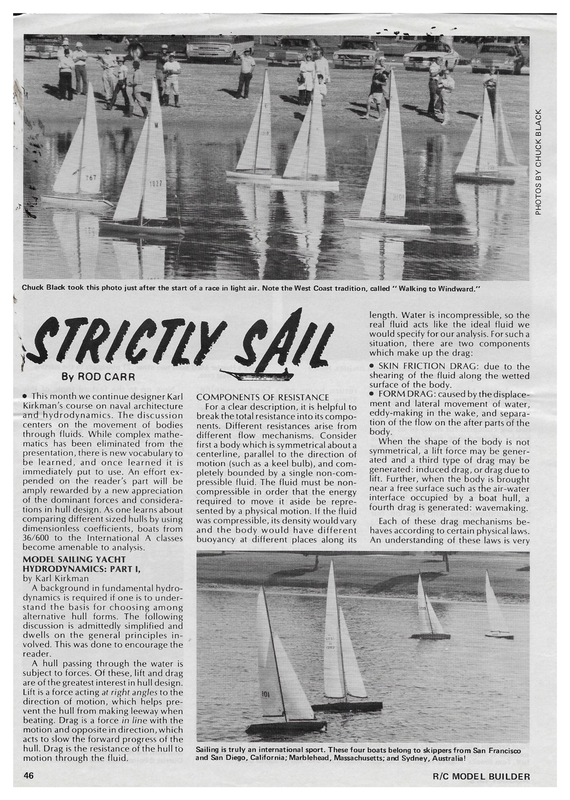
PHOTOS BY CHUCK BLACK FREES Chuck Black took this photo just after the start of a race in light air. Note the West Coast tradition, called ‘‘ Walking to Windward.” length. Water is incompressible, so the real fluid acts like the ideal fluid we would specify for our analysis. Forsucha situation, there are two components which make up the drag: @ SKIN FRICTION DRAG: due to the shearing of the fluid along the wetted surface of the body. By ROD CARR @ This month we continue designer Karl Kirkman’s course on naval architecture and hydrodynamics. The discussion centers on the movement of bodies through fluids. While complex mathematics has been eliminated from the presentation, there is new vocabulary to be learned, and once learned it is immediately put to use. An effort ex- pended on the reader’s part will be amply rewarded by a new appreciation of the dominant forces and considerations in hull design. As one learns about comparing different sized hulls by using dimensionless coefficients, boats from 36/600 to the International A classes become amenable to analysis. COMPONENTS OF RESISTANCE For a clear description, it is helpful to break the total resistance into its components. Different resistances arise from different flow mechanisms. Consider first a body which is symmetrical about a centerline, parallel to the direction of motion (such as a keel bulb), and completely bounded by a single non-compressible fluid. The fluid must be noncompressible in order that the energy required to move it aside be represented by a physical motion. If the fluid was compressible, its density would vary and the body would have different buoyancy at different places along its @ FORM DRAG: caused by the displacement and lateral movement of water, eddy-making in the wake, and separation of the flow on the after parts of the body. When the shape of the body is not symmetrical, a lift force may be gener- ated and a third type of drag may be generated: induced drag, or drag due to lift. Further, when the body is brought near a free surface such as the air-water interface occupied by a boat hull, a fourth drag is generated: wavemaking. Each of these drag mechanisms behaves according to certain physical laws. An understanding of these laws is very MODEL SAILING YACHT HYDRODYNAMICS: PART I, by Karl Kirkman A background in fundamental hydrodynamics is required if one is to understand the basis for choosing among alternative hull forms. The following discussion is admittedly simplified and dwells on the general principles involved. This was done to encourage the reader. A hull passing through the water is subject to forces. Of these, lift and drag are of the greatest interest in hull design. Lift is a force acting at right angles to the direction of motion, which helps prevent the hull from making leeway when beating. Drag is a force in line with the motion and opposite in direction, which acts to slow the forward progress of the hull. Drag is the resistance of the hull to motion through the fluid. 46 Sailing is truly an international sport. These four boats belong to skippers from San Francisco and San Diego, California; Marblehead, Massachusetts; and Sydney, Australia! R/C MODEL BUILDER
cert S choices or when analyzing the performance of a particular hull. Let’s take them one by one and inspect them more closely. SKIN FRICTION Whena flat plate is pulled through the water, the water molecules nearest the plate try to stick to the plate and are dragged along. Those nearest the plate approach the speed of the plate. As one moves out into the fluid, the speed drops off until a point is reached that is undisturbed by the passing ofthe plate’s surface (see Fig. 1). The portion of the fluid nearest to the plate is called the boundary layer. Careful measurements have been made which allow us to determine the amount of energy required per square foot of hull surface to drag the boundary layer along. This is called “‘specific resistance,’ since it refers toa given area at a given speed. If we change the area or move the plate at a different velocity, we will obtain a different number for the drag, due to skin friction. To allow comparison between different sized plates moving at different speeds, the hydrodynamicists have found the drag coefficient to be useful. One measures the drag, then divides by both area and the square of the velocity. As an equation, it appears as: C= D/AV? where: C = non-dimensional drag coefficient D = drag A= area V2 = velocity squared Further investigation showed that further benefits resulted if a parameter called the Reynolds number was used. The Reynolds number (Rn) is named AUGUST 1979 after its discoverer, Osborne Reynolds, and relates the length of the plate to the velocity at which it is moving: We can compute skin friction drag on a hull if we know its area, speed through the water, length, and have access toa C vs. Rn plot. Refined versions of this procedure would take into account the Rn~VXL If we measured the drag of many plates of many sizes at many speeds, we would find that they could be plotted as density and the viscosity of the fluid. Since we use water, we can look for relative differences to guide our choice of better hull forms. in Figure 2. Now sure in the knowledge that any flat plate will fall on that curve, we can predict the drag (D) of any plate as Two distinct types of flow can exist adjacent to a body’s surface. At very low follows: speeds near very smooth surfaces, the flow is hardly disturbed and little 1) Compute Rnby knowing the length of the plate and choosing a value for the velocity it will be moving. 2) mixing occurs between adjacent layers of water. This is laminar flow. If the speed increases or the fluid is disturbed or the surface is rougher, mixing can occur between adjacent layers of the fluid. Little parcels of higher velocity fluid are mixed outward into the slower water farther from the hull surface. This flow is called turbulent. The change Using Figure 2, move vertically upward to the curve, then left to the C scale, reading off C1. 3) Using Equation 1, we know all except the drag (D). Rearrange the equation and grind out the answer: D=Cx AV? Ee | | | | | pos TAS intportant when making initial design bedea te sroe Ron Battershill attempting to lengthen the hull of his Epic in hopes of increasing the hull speed. Andy Littlejohn, Sr., gets himself ready to do his thing with his LJ-50. Sure looks like a clean, relaxing sport. BOUNDARY LAYER ; se See | Pale! 2 | oe SCHEMATIC VELOCITY ! O | LTE EV TE PLATE MOVES AWAY = Ve oe aA AT REST PROFILE FIG. 1 A 47
je howe from 53 all beat om we laminar to turbulent is termed transitional flow. A composite plot of many data points for C (skin friction drag coefficient) versus Reynolds number is given in ~ Figure 3. Notice that the transition flow \ FIG. 2 e SS happens over a range of Reynolds numbers. Also, we see that laminar flow occurs at low Reynolds numbers, while A Jew wo ei ~N ~ ° es: tutbulent flow is more likely at hig ner Reynolds numbers. *, = =~ ~~ Cc FIRM RESISTANCE ~ <7 ~ “Form drag results from the thickness = of a body and the requirement for the ~e water to move out of the way as the body asses. Part of this drag is caused by the sess eee evelopment of a “‘super velocity,” the «Ush of the adjacent fluid parcels to Yio the distance out and around the dy. Since the fluid is incompressible, a pressure difference is caused by the arrival of the body. Both of these pro- GS -@- Rn =) Ay cesses require a continual input of energy, and since this energy is extracted from that given to the hull by the FIG. sails, it appears as drag, or a loss in propulsive force. The amount of form drag from a given body is affected by the Reynolds number of the flow. In Figure 4, the drag coefficient for streamlined foils (like a fin of a fin keel) is plotted SKIN FRICTION DRAG COEFFICIENT VS. R,, 0.010 0.009 + 0.008 + a against Reynolds number. The scales are 0.007 + o somewhat different, but the plots for flat 5 \plates are identified. Common in the 0.006 + bo oO diagram is a drop in the drag coefficient between a Reynolds number of 105 and = 0.005 + Le lw 8 2 10°. 0.004 + rf c A very similar plot can be made for Q other streamlined bodies, such as keel bulbs. It shows the same general shape, 2 0.003 + ° _ 2 including the drop in drag coefficient at oc Ww the 105-10 Reynolds number area. | > INDUCED DRAG 0.002 + =< ” Whena foil, bulb, or hull is placed at an angle to the flow, another drag appears. A typical sailboat actually crabs sideways while it is going to windward. By so doing, the fin and hull createa lift force which counteracts the sideways push of the sails. This allows the boat to make progress to weather, rather than being simply blown to leeward. The price we pay for this assistance is in- duced drag, or drag due to lift. 0.001 104 fess 102 1910 10911 9) aN 10 Next month we will consider the problems associated with the hull and how wavemaking resistance and wake formation become a part of the designer’s arsenal. | would appreciate comments from you readers as to the appropriateness of the material being tech- nical? If you'll give me your reactions, I'll be better able to provide the kinds of columns that meet your needs. Il field questions at 7608 Gresham St., Springfield, VA 22151, if you'll provide a stamped, self-addressed envelope. Rs 10% 100 * presented. Is it helpful? Is it too 107 FIG. 4 — SECTIONAL DRAG COEFFICIENT VS. R,, deeply submerged bodies, and all can affect the performance of partially submerged bodies. * 106 R, (REYNOLDS NUMBER) All the foregoing applies directly to * 10° Nos re: o = S = ” 1.0 a} : wi o 2 O gif es) : o/o = ro P s : x 0.1 S Qa st °fe)gop oO — od ~= os 5 ‘ TIC = 36% ae Ww nn Pla 0.01 5 Te Z — ye {Map _ | TIC = 12% al Loy ai zs : E TURBULENT Flow | 0.001 102 : ‘ 3. 104 3OR 10° 10® 107 REYNOLDS NUMBER ({R,) 108 109 1010 op R/C MODEL BUILDER