- Title. Author. Summary

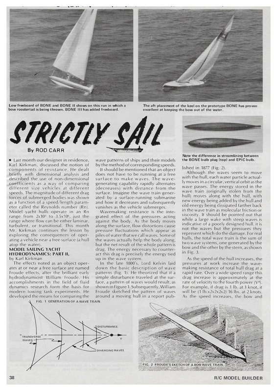
— ._—_— = _ = Low freeboard of BONE and BONE II shows on this run in which a bow roostertail is being thrown. BONE III has added freeboard. The aft placement of the keel on the prototype BONE has proven excellent at keeping the bow out of the water. STRICTLY CAI By Sen ROD CARR @ Last month our designer in residence, Karl Kirkman, discussed the notion of components of resistance. He dealt briefly with dimensional analysis and described the use of non-dimensional coefficients as a way of comparing different size vehicles at different speeds. The magnitude of different drag forces of submerged bodies was shown as a function of a speed/length parameter called the Reynolds number (Rn). Model yacht hulls operate in an Rn range from 2×10* to 3.5×10®, just the range where flow can be either laminar, turbulent, or transitional. This month Mr. Kirkman continues the lesson by exploring the consequences of oper- ating a vehicle near a free surface (a hull atop the water). MODEL SAILING YACHT HYDRODYNAMICS: PART II, by Karl Kirkman The effects noted as an object operates at or near a free surface are named Froude effects, after the brilliant early hydrodynamicist William Froude. His accomplishments in the field of fluid dynamics research form the basis for modern towing tank experiments. He developed the means for comparing the FIG. 1 Note the difference in streamlining between the BONE bulb plug (top) and EPIC bulb. wave patterns of ships and their models by the method of corresponding speeds. It should be mentioned that an object does not have to be running at a free surface to make waves. The wavegenerating capability rapidly alternates (decreases) with distance from the surface. Imagine the wave train generated by a surface-running submarine and how it decreases and subsequently vanishes as the vehicle submerges. Wavemaking resistance is the integrated effect of the pressures acting against the body. As the body moves along the surface, flow distortions cause pressure fluctuations which appear as piles of water that we call waves. Some of lished in 1877 (Fig. 2). Although the waves seem to move with the hull, each water particle actually moves ina circular, vertical orbit asthe wave passes. The energy stored in the wave train (originally stolen from the hull) moves along with the hull, with new energy being added bythe hull and old energy being dissipated farther back in the wave train as molecular friction or viscosity. It should be pointed out that while a large wake with steep waves is indicative of a poorly designed hull, it is not the waves but the pressures they represent which do the damage. For real hulls, the total wave train is the sum of two wave systems, one generated by the the waves actually help the body along, but the net result of the whole pattern is drag. The energy necessary to counter- bow and the other bythe stern, as shown in Fig. 3. act this drag is precisely the energy tied up in the wave system. In the late 1800’s, Lord Kelvin laid down the basic description of wave patterns (Fig. 1). He theorized that if a simple disturbance traveled at the surface, a pattern of waves would result, as shown in Figure 1. Subsequently, William Froude sketched the pattern of waves around a moving hull in a report pub- As the speed of the hull increases, the pressures at work increase the wavemaking resistance of total hull drag at a rapid rate. Over a wide speed range this drag increase is approximately at the rate of velocity to the fourth power (V4). For example, if drag is 1 lb. at 1 knot, it will be (1 Ib.x2x2x2x2) 16 lbs. at 2 knots. As the speed increases, the bow and GENERATION OF A WAVE TRAIN. ~~ DISTURBANCE ~ TRANSVERSE_ WAVES LILLE DIVERGING WAVES . 38 FS TCH OF = IES Zz, z Ze BOW WA Ae See R/C MODEL BUILDER
RESISTANCE zi HULL SPEED SPEED ———————_a FINE END HULL FIG. 5 BOW AND STERN WAVE SYSTEMS. FULL END HULL RESISTANCE stern wave patterns intermix, resulting in alternate reinforcement or canceling out. Total resistance increases, but has Superimposed on it smaller additions or diminutions of drag. These humps culminate in one final hill which sets the hull speed for a displacement (nonplaning) hull. Fig. 4shows a non-dimensional resistance coefficient versus speed for a typical 50/800 hull. The large hump which sets hull speed occurs when the length of the waves in the wave train is nearly equal to the waterline length. To move faster, the SPEED DIFFERENCE AT SAME DRAG MID—RANGE WEAKNESS | OF FULL END HULL hull must literally climb up its own bow wave, which requires a tremendous amount of energy. One usually sees this happen when a SPEED gust hits a flattish- bottomed model and it “‘planes away.” What might the designer do to raise the allowable hull speed of his model? First, one can strip weight out of the boat, reducing the intensity with which it disturbs the water surface and thereby reducing the wavemaking resistance. If the rules allow it, a length increase will tical limit to this approach is the increase in wetted surface which comes with the long hull, and an increase in skin friction. A second change would be to increase the fullness of the ends of the hull. Full- RESISTANCE help, since a faster moving wave train will be generated by the longer hull, raising the hull speed allowed. The prac- ended hulls have a potentially higher speed at the same resistance. The trade- off is the acceptance of slightly more drag in the mid-range speeds, as shown in Figure 5. As mentioned before, yacht design is commonly a series oftradeoffs; you don’t get something for nothing! The balancing of tradeoffs is one of the fascinating parts of the process. As part of the development of the SPEED Continued on page 98 SEPTEMBER 1979 39
DAaLRK. wv Sailing…… Continued from page 39 BONE 50/800, a series of towing tank tests of existing hulls were carried out at constant displacement. Figure 6 shows the results for the EPIC and the WIND II. The EPIC is a narrow, circular-sectioned hull, while the WIND II is a nearly flatbottomed hull. At very low or very high speeds, the WIND II is the boat of choice, for in these regimes its resistance is less. In the mid-range, however, the EPIC shows less resistance. Note that at the higher speeds, planing will initiate at less resistance for the WIND II, asshown in Figure 6. * * * The next article in this design series will discuss lift; how it is generated, the drag it induces, and so on. | will continue to field questions accompanied by an SASE. Rod Carr, 7608 Gresham St., Springfield, VA 22151. e@ a I CIES