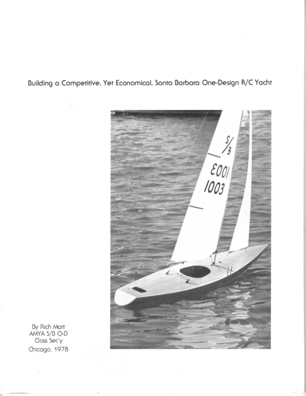
Written in 1978 by Rich Matt, then American Model Yachting Association (AMYA) Santa Barbara One-Design Class Secretary, this booklet explains how to assemble a competitive Santa Barbara One-Design radio-controlled racing yacht at lower cost than a complete commercial kit. Matt compares open-design and one-design racing, outlines the Santa Barbara class’s handling and portability advantages, and recommends buying the essential fiberglass hull and keel while sourcing spars, sails, fittings, adhesives, and other materials separately. He provides contemporary specifications, suppliers, four shopping lists, and estimated costs. An opening discussion explains two-channel radio control and the sail-sheeting mechanism used to adjust the mainsail and jib.
The construction instructions then proceed through five parts: selecting and acquiring materials; reinforcing the hull and fitting structural members, keel ballast, and rudder; installing the radio and sail-control equipment; applying a plastic-laminate deck and making removable hatch covers; and completing the mast, booms, standing and running rigging, sails, and finishing details. Numerous photographs and a rigging plan illustrate the work. The emphasis throughout is on careful fitting, accessible and reliable equipment, sound sailing performance, and economical workshop methods. Prices, supplier addresses, radio technology, and some procedures reflect the book’s 1978 publication date.
Photographs and Rigging Plan. An extensive introductory sequence of construction photographs shows the hull framing, radio and sail-control installations, deck work, hatches, and finished yacht. A full-page drawing illustrates the sail plan and rigging details. These preliminary pages are not numbered as formal parts.Santa Barbara O-D Specifications. Gives the principal dimensions, displacement, and sail area of the Santa Barbara One-Design, including its 70-inch overall length and 1,100-square-inch nominal sail area.Note. Introduces the functions of the sail-control winch and radio equipment, explains basic sail trim on different points of sail, and discusses practical choices for a reliable two-channel system.Part I: Why the Santa Barbara O-D? What’s Needed, and Where to Get It. Discusses the popularity and racing characteristics of the class, contrasts one-design with open-design boats, and compares complete kits, short kits, and individually sourced components. Includes supplier information and four detailed shopping lists for the hull and fittings, rigging, sails, and locally obtained materials.Part II: Preliminary Construction Procedures: Installation of Sheer Strips, Bow and Transom Blocks, Thwarts, Deck Stringer and Rudder. Guides the builder through preparing a support cradle, roughening bonding surfaces, fitting wooden reinforcement and deck-support members, aligning the rudder, and filling and weighting the detachable keel.Part III: Installing the Radio Gear and Sail Sheeting Mechanism. Details the positioning and removable mounting of the sail-control unit, receiver, servos, and batteries, with attention to balance, moving-arm clearance, hatch access, sheet runs, and rudder linkage.Part IV: Installation of the Plastic Laminate Deck and Making the Hatch Covers. Explains shaping and epoxying the laminate deck, trimming its edges, marking and cutting the two openings, and forming, fitting, and securing Plexiglass hatch covers. Alternative hatch arrangements are also considered.Part V: Final Assembly: The Spars, Hardware, Rigging and Sails. Covers deck fittings, mast and boom fabrication, spreaders, jumper struts, stays, turnbuckles, bending on the sails, routing and adjusting the sheets, and final painting and rig tuning before sailing.Recommended Hardware. A final illustrated reference page identifies commercially available rigging and deck fittings, with descriptions and period prices. This is a product reference sheet rather than a separately numbered appendix.
Building a Competitive, Yet Economical, Santa Barbara One-Design R/C Yacht By Rich Matt AMYA S/B O-D Class Sec’y Chicago, 1978 ���������������4v0P Trae 4 | 4.20 NO Bos \ Taaeh Ae ‘ O+APi4TaR . Mend s 12° a Anwer Ore meow Tr C Pa. -2 SGAN ETIB varee Sweoue = DETAIL $cae Bowsae Arsen 7%” D4LTAG | Su 7PsRr “JiBs 74 47 Swrsv2 4 Ss z BEND Sa. 2 INSTR D2 LEVEE Ow LATION SM Rov £997 vei kere i i es TT Oownv £ Somer ar A Donny ‘Ce Se2tfve. Cor -Oor < Aree NAY SerAsw Sood 2. Sakive fe YY TING 27 vw CF END Down Fare Sef £1 Aro Smee re 4ox4w PPTL TION. 262 i Bon aucwn er \ Wy, qn ymasT £0CA710 6 FoRWARL TURN acne \ A “ Ss VANS _ Swivee — J GoosSHNLCK TeX \ MaAIn Boom _ ay SANTA ONE BARBARA DESIGN R/C RACING YACHT Wf �Building a Competitive, Yet Economical, Santa Barbara One-Design R/C Yacht Santa Barbara O-D Specifications 70" (177.8 on Length Overall sssecceeseccevevees 62" (157.5 em vees sesecec ne Nominal Load Waterli 13" (33.0 cm) ccevens ccceccc Maximum Beam sesecce (33.0 cm ) 13" eseeone seeeeee Nominal Draft eoeveee in. (7100 sq. cm) sq. 1100 s sseee ecees eeves Area Nominal Sail 28 lbs. (12.7 ke.) Nominal Displacement sescecesssoes Note: of an inexpensive, yet This booklet is intended to describe the assembly is made to the other essentials competitive, S/B O-D. Only necessary reference common to a complete R/C yacht: a sail sheeting mechanism and a two or three channel radio. isms can be obtained by More complete information about sail sheeting mechan description: The purpose of writing the manufacturers. But, to provide atobrief trim, or otherwise set, the jib is a sail sheeting mechanism (sail control) posit ioned most advantageously in and mainsail booms so that the sails are relation to the wind and the boat's direction of travel. For example: d be eased out When the boat is sailing downwind its sails shoul to expose as as so rline cente as far as possible from the yacht's from behind wind the With wind. much sail area as possible to the it is in effect pushing the boat along, the sails should then bd made to resemble an outstretched umbrella. When the boat where the wind is be set where they overtrimmed so as is on a course 90° to otherwise on the side are not out so far as to overpower the boat the wind, or 4 point of sail of the boat, the sails should to flutter nor should they be and cause excessive heel. When the yacht is sailing as close into the wind as possible,true of the wind's usually a minimum of about 45° off to either side as close as held and in ht broug be d direction, the sails shoul possible to the yacht's centerline. trim the sails. On a R/C Aboard a "people boat" it is the crew's job to "sail l unit" or "sail model yacht a mechanical device called a "winch", radio contro d comman of the skipper sheeting mechanism" is installed that will at the fishin g line, called "sheets" position the sails where he wants them set. Strong mechanism to the two when used for the purpose, are led from the sail sheetingagains t the sails, pressure sail booms. A strong wind exerts considerable sturdy ful device. Since power and therefore, the sail sheeting system must be a other, only each to the two sails, the main and the jib, are trimmed parallel one sail control unit is required. It is possible to build your own sail winch. But, it is not recommended, run prove The sail control mechanisms available commercially will in the long �to be a wise investment, especially to the novice skipper. Only seldom will a regatta be won by a yacht having a homemeade sail control installed. The sport's champions believe in the efficiency and reliability of the commercial units. Average price of a ready-to-use sail control would be about $75, information about the units available, .For detailed write Vortex Model Engineering, Probar Design and Sail Engineering (See manufacturers list below for addresses. ). As for the radio gear... channels. You will need a system having a minimum of two One of the other two servos is linked directly to the rudder to accomplish steering control; the sail control unit. the other is used to actuate the switch operating Perhaps, one-third, or even one-fourth, the population of R/C skippers will use a three channel or more elaborate radio and install an additional accessory function to their yacht. would be fine-tuning jib out to one side jib trim, Examples of such accessory functions an adjustable backstay, or a device to flip the or the other when running downwind in light air. decide to get into R/C sailboat racing, If you it won't take long to discover that these extra functions do little more than provide an excuse for doing poorly inarace. argument. At any rate, the merits of "go-fast" gadgets are good subject for Be confident in the adequacy of a two channel radio. It should be mentioned that very few skippers bother to secure the radio gear in waterproof boxes. More than likely, Only one out of a hundred, would be a good estimate. they are the type to share their model boating time with gas powered hydroplanes, and it then becomes a matter of convenience. In R/C sailboats the threat of water damage to items below deck is a factor only in heavy weather. Even then, there isn't an experienced R/C skipper around that considers it any kind of a blow to his pride to use masking tape as a secondary seal around his hatch covers. A suggestion: readily. Opt for a brand of radio that enables you to change frequencies There are sets available that offer inier-changeable crystals making it possible for you to have this flexibility. Regatta Directors must limit the number of entries on any one frequency to three, maybe sometimes four, and it is a bit of a pain to show up at the local pond for some casual racing and find another skipper or two using your frequency therefore making it necessary to share time on the water. Do yourself a favor and consider the additional expense of a multi-frequency transmitter and receiver. KHKEK Part I - Why the Santa Barbara O-D? What's needed, and where to get it, In 1977, some 1,500 R/C model yacht racing enthusiasts were members of the American Model Yachting Association (AMYA). According to the AMYA Quarterly Newsletter forty-five sanctioned clubs sponsored almost the year. Even though the AMYA is only six years old, 100 regatta events during these numbers indicate that the hobby and sport of R/C model yachting is well established and shows every indication of continuing prosperity. By the number registered, five classes of model yachts are particularly popular: 50/800, 36/600, Santa Barbara O-D, Heritage 12-Meter and Newport 12-Meter. What class a personchooses to get into is often, and logically, what is active and popular in his area. one Also, determined by it is not unusual for more than class to be abundant in a particular area giving cause to acquire another �yacht of the different class in order to make it possible to participate in more regattas. What makes owning more than one yacht somewhat practical is that a model yacht's innards, the sail sheeting mechanism and the radio gear can be readily transferred from one boat to another. Since these two items represent more than half the expense of the model yacht, a person can almost justify owning an additional yacht in order that more use can be made of the electronic and mechanical equipment. Another matter to consider by a person planning to become involved in R/C sailing, and who is trying to decide what class to choose is that there are two varieties of classes: open-design and one-design. Open-design classes, as the name implies, permit hull designs and sail plans that may vary considerably, and yet, the boats are still eligible to compete against each other. The measurement limitations of the 50/800 and 36/600 open- design classes are specified in terms of overall hull length and total square inches of sail area. For instance, 50/800's are permitted a maximum hull length of 50" and a maximum sail area of 800 square inches. The yachts remain competitive to each other because they are of the same "size", Open-design classes have appeal to those who have experience and ideas in yacht design and who are capable of doing their own scratch building. The basic idea behind it is to show up for a regatta having a boat that is faster and more maneuverable than those sailed by the competition. Development of design becomes a necessity. Obsolescence of a design becomes a reality. The trend within the 50/800 Class, for example, indicates that a winning design's longevity as a winning design is good for one year. On the other hand, there are the one-designs which include the Santa Barbara, Heritage 12-Meter and Newport 12-Meter. By "one-design" is meant that all yachts registered in the class are near identical in design and proportions, One-designs, so far, can not be scratch built. This is because the fiberglass hull must be pulled from a mold that has been approved by the AMYA Class Secretary as accurate to the class design. Sail and spar dimensions are dictated by the class rules, With a one-design a class member has assurance that his or her racing competition will be using a yacht that is identical to his or her own, and it then becomes the sailing skill of the individual skipper that determines the regatta winner, Racing tactics, familiarity with the boat, tuning skills and a little bit of luck make the difference in one-design racing. Another important virtue of one-design classes is that a well maintained model yacht, one that was assembled with care to begin with, will not wear out or become obsolete. As long as the class itself retains its popularity and activity, the boat will retain its resale value. From the beginning, one of AMYA's most popular, most active, and most competi- tive one-design classes has been the Santa Barbara One-Design (abbr. : S/B O-D). The yacht was designed and introduced in 1964 by Tom Protheroe of Santa Barbara, California. tribution There are in existence today almost 1,000 S/B O-D's, And, the dis- of skippers, fleets and regatta activity across North America is the best of any one-design class. Experienced R/C skippers recognize the S/B O-D as a modern classic. It is a boat that performs well in light winds as well as being one that remains very manageable in heavy weather. As compared to many other yacht designs, it has no bad habits. The S/B O-D's maneuverability in tight quarters around the starting line and around crowded course marks is a real joy. If set up and tuned properly �for the existing wind conditions, it will sail a straight and constant course. Also, being a large model yacht (almost 6' in length) and weighing close to twenty-five pounds, the S/B O-D remains readily visible at a distance while Sailing a steady, predictable course, The keel, sail rig and rudder are readily removeable making the S/B O-D easy to transport and stow away. The class's serious competitors will agree boat is one of the easiest to transport to distant regattas, travelling by air, as the yacht's that the For instance, original packing. considered as carry-on baggage. The keel can be fitted into your suitcase When parked under the seat ahead, for a good footrest. Air travel with boats of other classes is usually much The of a challenge. the fixed keels exagerated mast of the length of the or it will make more and when everything but the keel will fit securely into the carton used open-design classes other one-designs mentioned make packaging and handling comparatively difficult. Once at the lake, it takes only a few minutes to secure the S/B 0-D's keel, sail rig and rudder in place. Vortex Model Engineering, 210 E. Ortega Street, Santa Barbara, CA 93101, is the only source for the S/B O-D, Other manufacturers could apply to Vortex for license to produce the yacht and to the AMYA S/B O-D Class Secretary for approval of the product, a challenge but they have not. to manufacture Why? Well, perhaps they realize the quality of product at the price it would be Vortex asks, Vortex qualifies as the most experienced and most respected manufacturer of R/C model yacht kits. been Model yachts are carefully researched, Still, their in all, only business, and their products have a prospective purchaser's first reaction to the price tag on the complete S/B O-D kit, as offered by Vortex, that the yacht is one very expensive item, that the kit is absolutely complete, It must be kept in mind, and about half of the cost is however, is represented by the custom made stainless steel hardware and rigging parts. The complete S/B O-D kit package sells for $378.00. parts, all hardware and even together. The This includes sails, all the resins necessary for bonding the various parts only item left to buy separately and locally is the lead shot used for keel ballast. Assembly and all installations are uncomplicated and quick. What has to be of the one hobby world's most carefully prepered Manuals accompanies the kit making making experience instruction it possible for those with limited model to put it all together with little fuss and still wind up with a beautifully finished model yacht. For those modelers reluctant to make the also offers a S/B O-D "Short Kit". keel, the bolts and cockpit cover. rigging Wire, Vortex sails and hardware. to This alternative the fiberglass is the above mentioned You may then opt to or otherwise provide your own, require more research on your part facturers. Also provided The price of the Short Kit is $158.00. purchase from other sources, spars, in the full kit, sealing washers necessary for joining the two, deck and the clear butyrate assembly manual. investment Included with this package are the hull and bonding materials, to the "Full Kit" will learn what is available from other manu- A S/B O-D put together by the Short Kit method utilizing spars, sails and hardware from other sources will cost about $275.00 all together. Vortex also publishes an extensive parts list. any of the components particularly for the that go into the cost conscious, to complete consider. the fiberglass hull and keel you will have the a S/B O-D, It is possible to buy separately kit. two This is then a third method, By purchasing from Vortex only items basically essential for Certain measurements as specified in the AMYA S/B O-D Class Rating �Rules will need to be adhered to when completing the construction, but this will not be a problen. It will be the purpose of this booklet to explain what it takes to assemble a S/B O-D by this third, alternate method. Described, will be the things needed, where to get it all, and how to put everything together so that you finish up with a competitive, yet comparatively inexpensive S/B O-D. One big objective will be to show that it is possible to assemble a S/B O-D by this third method for virtually the same cost as that required for assembling another R/C yacht of another class: roughly, $220.00. As you might suspect, putting together a S/B O-D by this third method will require more in the way of time and effort, and a bit of chasing around when gathering the necessities. With the photographs and descriptions provided, the actual assembly should be within the skills of most modelers, There are four sailmakers to recommend. Also, three hardware manufacturers, three sail sheeting mechanism manufacturers, and a number of R/C electronics suppliers that are all worthy of consideration when planning your S/B O-D per the Short Kit or by the method to be described here. Since many parts are needed, and their choice can be by personal preference, the possibilities for variety are great. To'learn what products are available send off self-addressed, stamped envelopes with a note explaining your interest in making a S/B O-D to the following manufacturers... S/B O0-D Kit, Short Kit, Parts: Vortex Model Engineering, 210 E, (catalogue - $1.00) Ortega St., Santa Barbara, CA 93101 Hardware & Fittings: Vortex Model Engineering - address above, Probar Design, P.O. Box 639, Escondido, CA 92025 A.J. Fisher, Inc., 1002 Etowah Ave., Royal Oak, MI 48067 Sail Sheeting Mechanisms: Vortex Model Engineering - address above. Probar Design - address above. Sail Engineering, P.O. Box 8439, Richmond, VA 23226 Sails: Vortex Model Engineering - address above. Carr Sails, 7608 Gresham St., Springfield, VA 22151 Black's Sails, 4761 Niagara Ave., San Diego, CA 92107 Protheroe Model Boat Works, P.O. Box 30073, Santa Barbara, CA 93105 Radio Equipment: Check with your local hobby dealer. Inquire about two or three channel radios having interchangeable frequencies. The yacht assembled as the example for this booklet uses a combination of hardware items from both Vortex and Probar, the newly introduced Vortex SC-3 sail sheeting mechanism, Carr sails and Kraft radio gear. The "Shopping Lists" printed below itemize everything necessary. Whether or not to substitute certain parts and pieces with those available from another manufacturer is your decision, All the suppliers named above are reputable, and their products were all originally designed with model yachting use exclusively in mind. Both Vortex and Probar have copies of the "Shopping Lists". When ordering just include a check and mention that you intend to assemble a S/B O-D per this booklet. There is no need for you to re-itemize the lists. �S/B O-D "Shopping List #1" Vortex Model Engineering, (1) 34 (2) ‘54 (2) (1) (1) (1) (1) (1) (1) (1) (1) (1) 210 E, Ortega St., Santa Barbara, Santa Barbara O-D Fiberglass Hull Santa Barbara O-D Fiberglass Keel Bolts, 1/4-20 x 1-1/4" Flanged Head, @ 35¢ Sealing Washers, @ 10¢ Mainsheet Block Assemblies, @ $3.25 Main Traveler Rail Assembly 1/16" Braided Nylon Line Aluminum Rudder Rudder Shaft Log Tiller Tiller Cap Screw, 6-32 x 1/4" 6" Unanodized Aluminum Mast Clevis with 12" Rod Tub of Cab-0-Sil Filler CA 93101 $52.90 40.70 +70 »20 6.50 7.90 075 eld 2.00 70 015 9.75 80 20 $130.40 Note: The carton will be shipped by truck because it exceeds UPS and Parcel Typical shipping expenses are about $20.00 A good reason for making this a group project is that two or three s/B O-D cartons can be sent to one address for the same expense as only one carton, Post maximum dimensions. S/B O-D "Shopping List #2" Probar Design, tn (1) (1) tf (4) (4) tt (1) (1) (1) (1) (1) (1) ‘3 (3) P.O. Box 639, Escondido, CA 92025 A-9 A-23 A-2 A-1 H-1 H-2 Rigging Wire Rigging Wire Swages, packet Bowsie Sheet Exit Guides, @ 50¢ Turnbuckles, @ $4.50 H-15 Boom Vang Pivot, 1/2" H-13 H-17 H-16 A-3 A-9 a-8 A-15 H-8 $3.00 75 .10 1,00 18,00 Chainplates, @ $1.00 Gooseneck, 4,00 3.50 1/2" 5.50 Spreader Assembly Diamond Jumper Masthead Fitting Sheet Metal Screws, packet Dacron Line Screweyes, packet Cleats, @ 50¢ 3.50 3.00 050 75 250 250 1.50 $46.20 S/B O-D #1003, the yacht described in this booklet, makes use of heat-formed Plexiglass (TM) hatch opening covers. for use as the main hatch cover, However, as an alternative to Plexiglass you might consider ordering from Probar their new clear molded plastic hatch cover (A-18 @ $5.50) and the new fiberglass hatch cover ring used as a base for the cover (A-20 @ $3.50). S/B O-D #1003 also makes use of a screweye (one of those in packet A-15) as the jib padeye. However, you might consider ordering one H-15 Eyebolt from Probar at $2.25 is sturdier and appearance-wise better Eyebolt, than the screweye. The H-15 Eyebolt If you order the H-15 you will still need the packet of A-15 Screweyes for other purposes. ‘ �S/B O-D "Shopping List #3" Carr Sails, 7608 Gresham Street, Springfield, VA 22151 S/B O-D #1003 is equipped with Carr's "Standard Suit" S/B O-D sails. These sails meet all measurement specifications of the S/B O-D Class Rating Rules. With battens and vinyl class insignia they are priced at $30.00. When ordering specify that the mainsail be fitted with a bolt rope for use with a Vortex aluminum mast, and also mention that the mainsail is to be "loose-footed", S/B O-D "Shopping List #4" Local Shops and Stores From the local sporting goods store you will need 12 to 14 lbs. of #8 lead shot for keel ballast. In the fisherman's supply corner find a packet of split rings 1/4" in diameter and three medium size swivel clasps. From the local cabinet maker pick out pieces of stiff, high-pressure, plastic laminate, such as Formica (TM), measuring 13" x 72", 12" x 7-1/2", and 6" x 4", From the local hobby shop you will need: Devcon 5-Minute Epoxy (two packages), Hobby Poxy II, a pint of casting resin and the necessary catalyst, a 6" x 12" piece of 1/8" plywood, and a pair of clevis rods for servo linkages. From the local hardware store get: sized roll of aluminized couple a cloth duct tape, large roll of i" masking tape, of medium grit sanding discs for use with an electric drill, brushes for spreading epoxy glue, a six acid two dozen spring loaded clothespins, of white automotive touch-up laquer, a medium an assortment of sandpaper sheets, a spray can another can of another color for painting on the yacht's waterline, eight 1/2" #4 sheet metal (self-tapping) screws, a 3' length of 5/16" dowel, a 3' length of 3/8" dowel, a 3' length of 1/2" dowel, an 8' length of window lath and an 8' length of window parting stop. 1-1/8" x 1/4" and parting stop 1/2" x 3/4",) If you decide to search out a (Note: Lath measures to make hatch covers out of Plexiglass, source. ment for window glass. Many hardware it will be necessary stores now stock the material as a replace- Two pieces of 1/16" thickness will be required: one 8" x 12" and another 3" x 5", Shopping Lists #1 (Vortex), #2 (Probar) and #3 (Carr) add up to an investment of $206.80, What additional expenditures are involved because of Shopping List #4 depend a lot on what you might all ready have your skills as a shopper. Plexiglass are The lead shot, on hand, what you can scrounge, plastic laminate, and wood strips and the items that you are bound to have to go out and buy. Together these items should cost between $20.00 and $30.00, As an alternative to a plastic laminate deck you might consider using mahogany plywood, the 1/8" variety, such as that used as facing on hollow-core interior doors, are, It makes for a serviceable deck, price at the local lumber yard. advantages. It is available good looking and distinctive deck. that is easy to fit and trim, The plastic laminate, in all you can resist picking out a marble, hull, It you can find a damaged door having enough good surface never require refinishing, sorts of colors, speckle the boat. however, And, chances intact for a good has definite patterns and or flower pattern, textures, If you will have a The laminate will last as long as the fiberglass and will resist is many times better than soft plywood. plywood deck and left one made of laminate are A few ounces are all that are scratches and gouges The differences in a manner in weight between a inconsequential to the performance involved, of �Working with plastic laminate will be a new experience for many modelers, especially those who are used to Monokote and balsa! Ordinary home workshop tools are adequate for working the material. Needed will be an electric drill, == its sanding disc accessory, an electric hand-held jig saw and a sanding block, local hardware store getting the other items, pick up a Remington, While at the tungsten carbide "Grit Edge" This blade (fine grit) blade for use with the hand-held jig saw. is about the only one to be trusted when Cutting laminate. Being a dense, brittle sort of stuff, plastic laminate requires care and patience to cut and trim. Look in the Yellow Pages under "Kitchen Cabinets and Equipment" to find regular users of the material, Visit the shop, explain what you need the laminate for, and ask to pick over the scrap inventory. Expect to pay about $1.00 per square foot for whatever you select. Again, if you plan to follow the recommendations necessary to mail orders and checks off to three Carr. of this booklet, suppliers: Vortex, it will be Probar and They each are aware of this project, and they have on hand a copy of the "Shopping Lists" as presented here. A note indicating that you plan to assemble a S/B O-D per this booklet will be adequate, rather than taking the bother to re-itemize waiting, goods the lists. gather store Expect to wait about together the hardware store, two weeks for deliveries. hobby shop, cabinet While shop and items. sporting Part II of this booklet will describe the preliminary construction procedures : installation of the wood sheer strips, bow and stern pieces, thwarts, deck stringer and rudder, Part III will deal with radio and sail sheeting mechanism installati on, Part IV describes the installation of the plastic laminate deck, making the hatch openings, and fitting the hatch covers. And, Part V will deal with the spars, hardware and sails. A quantity of photographs are involved; they are intended to make this an easy step-by-step assembly project. The drawing included will be particularly useful when performing the steps described in Part V. KEEKHK Part II - Preliminary Construction Procedures: bow and transom blocks, First, it is thwarts, necessary to prepare the yacht stationary. Installation of sheer strips, deck stringer and rudder. Just rested a cradle or some kind of stand for holding on the workbench, the hull's round bottom will roll around making fitting and gluing procedures difficult. Securing the keel in place and laying the hull on its side during construction will only make assembly awkward and inaccurate, A cardboard carton about 24" notched at the long, ends to conform to the The carton cradle is for use When at the the grass, lake, only in 15" high and wide, open at the top, and hull shape will make for a useable cradle, the workshop and when storing the yacht. an old blanket or scrap of carpet will serve better than a cradle, Lying on its side when not in the water, the boat will not be blown over by a sudden gust of wind; it will be easy to check sail trim by walking around and sighting down the mast; and it will be the sail rig. easier to set up or take down Prepare the cardboard carton to hold the yacht with the keel attached, Align the depth of the box's notches so that the base of the keel rests on the floor of the carton. Once the keel is weighted, and if the boat is suspended at the box's notches without the keel being direcly supported, the hull at these pressure points, there is the chance of deforming �Finish the cradle, rest the fiberglass hull in it, and you are ready to get started. Use a piece of coarse sandpaper to scratch up the inside top edge of the hull for about 1" down. You will notice a waxy residue from the fiberglass resin clogging the sandpaper. Without first sanding away this waxy stuff and exposing some clean scratched fiberglass, you would otherwise have a poor gluing surface. Whenever these instructions call for gluing something in place to the fiberglass, try to remember to first sand the area affected. Installation of the wood bow block, transom block and sheer strips comes next. Sheer strips run fore and aft, from bow to stern, on the inside top edge of the hull. Together with the bow and stern blocks, this wooden perimeter around the inside top edge of the hull serves as a gluing base for the deck. As recommended in Part I, you Should have purchased an &' length of clear pine window lath from your local hardware store. Lath measures 1/4" thick and 1-1/8" wide. For the bow block, cut off a piece 1-1/2" long, Place this small section at the bow and rest it on top of the hull there while marking it from below with a pencil. a sanding block to cut and fit it to shape. Once flush with the top edge of the hull and its sides sides. Use a finger to hold it Use a coping saw or jig saw and satisfied with its fit, its top not forcing the inside of the hull, glue it in place using 5-Minute Epoxy. Cut a 6" length of lath for use as a transom (rear end) block, This piece of wood will require some careful trimming. Three sides and the top must be shaped. A pencil, coping saw and sanding block, plus a bit of patience, will do the job. Use 5-Minute Epoxy to secure. Cut off another length of parting stop 6-1/2" long and set it aside for use later as the rudder thwart. Run the remaining length of lath through a table saw using a thin plywood cutting blade so as to bisect it lengthwise into two long, thin strips measuring 1/4" x (about) 5/8" x (about) 82". If you do not have convenient access to a table saw, use a sharp utility knife alongside a metal straight edge. You will be slicing with the grain, and a dozen careful passes with the knife should do the job as well as would the table saw. Cut the two 82" lengths down to two 67" lengths. One will be fitted to each inside top edge of the hull sides as the sheer strips. Notch the ends of these strips to accomodate the now secured bow and transom blocks. Fit them carefully. A good, tight fit against the blocks will insure that they will bow and force themselves to conform to the curve of the hull sides with a minimum of clamping when it comes time to glue them in place. It would be a good idea to determine the adequacy of your available clamps. In the few inches furthest towards the bow you may notice it necessary to use a "C" clamp on each strip to insure a tight fit to the hull. Allow the sheer strips to be a tad higher than the fiberglass edge, because once glued, the wood can be readily sanded flush. Run a strip of masking tape around the outside top perimeter of the hull so as to protect the outside gel coat finish from any excess epoxy that might squeeze up and over when gluing in the sheer strips. Once satisfied with the trial fitting, mix up some Hobby Poxy II and add some Cab-O-Sil filler to thicken it up a bit. Use an acid brush to apply the epoxy glue to both the sheer strip and the top 3/4" inside the hull. Position the sheer strips and secure them with the clothespins and clamps. Use a paper towel to wipe off any excess epoxy from the top edge so as to catch any drips. Turn the hull over resting it across a carton upside down so that any excess epoxy under the sheer strips will form a strengthening fillet along the underside. let harden overnight. �10 From the 8' length of parting stop (1/2" x 3/4") cut one 11-1/2" section and another 11-3/4", These are to be installed as thwarts crosswise the hull and epoxied to the sheer strips. The 5 fips edge will be the thwart's top, or botton, and the 1/2" edge would be the vertical sides. The 11-1/2" piece is installed so that its center is 30" aft from the tip of the bow, and the 11-3/ " piece 44" aft of the bow. sheer The strips. tops of the thwarts should come flush with the top edge of the Taper and angle the thwart ends to conform to the inside surface of the sheer strips, S/B O-D Class Rating Rules, per the American Model Yachting Association (AMYA), require that the hull's beam (width) does not exceed 13" or be less than 12-1/2", Check the beam measurement when fitting the thwarts, and double check prior to setting them in place with 5-Minute Epoxy. Be safe, try for a beam measurement of 12-3/4", Cut a 5" length of parting stop and fit under the forward it as a vertical riser from thwart down to the hull bottom, It will be necessary to trim off about 1/2" when getting it to conform to the shape of the keel socket on which it rests, Epoxy it into place. On the underside of the hull, a dimple about 7" forward of the stern, in the fiberglass marking the intended you will discover location of the rudder. Using a 5/32" drill make a hole for the rudder shaft. You will need inside the hull a thwart to support the rudder. For this purpose use the 6-1/2" length of lath cut off and set aside earlier. taper and angle Without removing more of its length than necessary, theends to conform to the inside shape of the hull when this thwart is located sideways across the hull and about 1-1/2" above the rudder shaft hole. While in the process of fitting the thwart ends, determine the thwart's center and drill a 1/4" hole to accomodate the rudder shaft log. rudder shaft log is the metal tube which serves as the the rydder shaft. Do not glue the thwart or log next intended step which is to insure With a tape measure hooked strips at a point 63" aft. hull sides. on the tip of the to hold Turn the hull upside down, it secure. rudder. then be measure hull sides Adjust the masking tape from the marks on the Double bow mark the top of the Place the rudder shaft up the over the to align sheer strips When equal on both sides according to square. Wait until the proper alignment. sheer Extend these pencil marks just a bit over on to the Use a strip of masking tape run from the To check, in place yet. the rudder's The housing and bearing for masking tape. the the rudder perfectly vertical. to the forward tip of the tape measure, Double into its hole, tip of the rudder the rudder board or business card and slip one under each end of the rudder top where meets the hull. Doing this should up a matchbook cover card- will line up the fore and aft angle it of the rudder shaft and prevent the rudder from later dragging on the hull when turned. turn When satisfied that the rudder the hull on over, necessary to refine grease, way Oil or wax inside the Fit the fit Once straight and log and hardened, thwart. It may be A shaft will prevent any epoxy that might Rough up the touch of ooze its fiberglass gluing Use 5-Minute Epoxy to glue the thwart and shaft log double Be secure with masking tape, then the ends with a sanding block, shaft log from being a problem. II and Cab-O-Sil filler. shaft of the thwart on the rudder areas with coarse sandpaper. in place, is held the rudder shaft up on this gluing job with a mixture of Hobby Poxy sure to make a hefty fillet around the base of the log. Using left over sheer strip material (bisected lath) cut an 8-1/2" length and install it "on edge" as a thwart 18" aft of the bow. Taper and angle the ends to �11 the butt neatly against the sheer strips. Epoxy the thwart's top edge flushandwith after length, 9" a to 5/8" x 1/4" top edge of the sheer strips. Cut another You now fitting the ends install it across the sheer strips 57" aft of the ybow. them number mentall later, s purpose ce have four thwarts installed, For referen 1 through 4 starting from the bow. The next step involves fitting the deck stringer. This is a length of parting and stop (1/2" x 3/4") running down the centerline of the hull from bow to stern goes r stringe deck the , thwarts #4 and #1 the Like resting on the four thwarts. edges "on edge" with the narrower sides making up the top and bottom and the wider notched be should stringer the of inch ost forwardm The being the vertical sides. of a 1/ " deep so that it fits under the bow block and into the bow area. The top in Keep block. bow the of surface top the with the stringer will then be level mind that the first 6" or 8" of the finished deck surface will be flat. The crown of the deck begins gradually from this point. The center of the #1 thwart will need to be notched about 1/8" deep and 1/2" across so that the stringer sets down into the thwart this little bit in order to maintain the proper deck crown. The stringer will rest on top of the #2 and #3 thwarts without the need for notches. in the same It will be necessary to notch the #4. thwart to the same depth, 1/8", and notched off cut be should r stringe the of end aft The manner as the #1 thwart. the to fit under and flush with the top of the stern block. As you proceed, rsight a has stringer from both the bow and then the stern to be sure that the stringe aft or smooth line with no high or low deflections. Whether viewed from forward, a the side, the stringer should follow the sheer of the hull and also provideand then crown for the deck that will be 3/4" high in the mid-section of the yacht not taper smoothly into the bow and the stern. Once satisfied with its fit, do control glue the stringer in place. Instead, set it aside until the radio and sail mechanism are installed. Cut two 3" pieces of leftover 1/4" x 5/8" sheer strip and use 5-Minute Epoxy to set one on each side of the hull in the forward corner formed by the sheer strip and the #2 thwart. These will serve as back-up blocks to secure the screws which will hold the chainplates. "Chainplate" is another word for the hardware item which secures to the yacht the wire stays which support the mast. It may be necessary to sand away the one corner of the back-up to fit around any excess hardened epoxy holding the #2 thwart to the sheer strip. You are now ready to plot the installation of the sail control mechanism and will the radio gear. That project can get a bit involved, Part III of this booklet keel. the weight to cover the matter in detail. Now, however, would be a good time hole in In order to get the lead shot into the keel it is necessary to drill a the keel to in drill and to the keel top. Fit your electric drill with a 3/8" bit, top to either side of the center seam. Drilling in to the center seam creates a risk of splitting the keel open. The combined weight of the keel, the bolts, ofthe lead, and the casting resin poured in to solidify the lead must be a minimum the 14-1/2 lbs. and a maximum of 16-1/2" lbs.. These numbers are a stipulation of be checked AMYA S/B O-D Class Rating Rules, and it is not unusual for keel weight to is a keel weight light a at regatta events. Whether a heavy keel is better than matter that has been debated for years. If a popularity contest were held, the shell, heavy keel fans would probably be the winners. In the belief that thea keel more little to up add will the bolts, and the resin necessary to secure the lead of ent equival the up Mix shot. than 2 lbs., measure out between 13 and 14 lbs, of t. catalys of drops ten about only a small coffee cup's worth of casting resin with �| 12 Pour about one-third the resin into the keel. and over so as to re-coat the inside Use a funnel. Wipe the funnel clean and dry with paper towels, pour in the lead shot. Pour Roll the keel around of the center seam adding a bit of strength. replace it in the keel hole, in’the remaining resin, and then keel so that the resin flows and covers the lead completely. be able to see all that is happening to mentally visualize. Use a dose inside the keel shell, of will power to resist and slowly rock the Naturally, but you won't it is all easy the urge bottom of the keel on the workbench as if to pack the lead down, to bang the Doing so, might result in a split keel. The big reason for not mixing a larger amount of catalyst to the casting resin is that it is important create heat, the Any heat smooth surface just that. that as the resin cures that might be of the keel. tape It's not a bad idea, once the resin has been poured in, If any heat does generate, hole, and submerging only the bottom half prop it up so that to rest the A piece of the When standing the keel in the bucket or tub for the resin to cure, could deform it will be harmlessly Be careful so that no water gets into the keel. over the that. slowly and does not Too many keels have been screwed up all ready by keel in a tub having 6" of water, dissipated. it does so generated by the curing process time the forward end of the keel of masking keel should prevent it will take the top is about 2" below horizontal. After plenty of time, perhaps a day or two later, test the resin for hardness by poking a dowel down the hole in the keel top. be necessary. original cup-full did not solidify the entirely. it in, Chances are, the keel back and forth so as would be the lead's top surface, pour it lead shot in. Only, keel upside down, seen filling the park it so this time, Flow the hole and The use of fine after covering the ounces turning the masking tape dark. harden, and hull keel socket, hull socket's edges, Set hole so turn the it can be the keel down and then become a plug for the hole, insure that the top of the Sand away any high Check the fit, tub. of resin and hole with masking tape, sandpaper may be necessary to sets properly into the the mix up another couple liquid resin into the area of the the resin will stay put, pour to flow the resin around what Tape the hole and return the keel to the second application has cured, seam and of resin will Mix up a half-cup of resin with only about ten drops of catalyst, slowly rock the Once the Another application it's none spots keel on the keel's too difficult. KEKKK Part III - Installing the radio gear and sail sheeting mechanism. As described in Part I of this booklet, an R/C model yacht requires at least a two-channel radio. actuate the One channel is for rudder control, sail sheeting mechanism. sail control, or "winch" is to set most advantageously in relation to The purpose the yacht's the wind and and the other is used to of the sail sheeting mechanism, two sails so that they are positioned the direction in which the yacht is moving. If you were to attend an R/C yacht regatta and look inside every boat to see how each skipper handled his radio and sail control installation, discover that the whole matter is a very individualistic seems to have his own ideas about what to use, and how to secure control everything in place. is usually installed first. how to use A few basic Its position is thing. it, you would Each skipper where to put it, considerations apply. important. The sail The weight should �13 be kept as low in the hull as possible; its swinging arm must not contact anything as it rotates; and the swinging arm must be situated properly in relation to the sheet exit guides. The radio gear is installed so that the servos are in proper position to operate the rudder linkage and to actuate the sail control switch, The sail control's battery is last to be installed; its accessability and weight placement being important, Also to be considered when installing all gear is that the sheets (lines led from the sail control mechanism to the sail booms) must not foul on anything if and when they go slack in light winds. And, since there is the chance that a small quantity of water might filter in through the sheet exit guides and from around the hatch cover, it is a good idea to install all your equipment at least an inch above the hull floor and the same distance away from the hull sides. The S/B O-D, being a comparatively large model yacht, has the space available below deck to accomodate any of the commercial sail control units. You can be confident that any of these sail controls are adequate for trimming the S/B O-D's 1,100 sq. in. of sail area, The unit selected for installation in S/B O-D #1003 is the recently introduced SC-3 Sail Servomotor by Vortex Model Engineering. The SC-3 took some two years for its development and production set up. it is readily available, the SC-3 should increase even more the popularity that Now of the S/B O-D Class. Over the seven years that Vortex has been in business, they have established a reputation for providing quality products, and because of this, many of their loyal customers have been waiting for the SC-3. For racing competition purposes the Sail Servomotor is able to trim the yacht's sails from full out to full in, or from full in to full out, in four to five seconds. Most of the more successful racing sailors agree that a sail control function should not be any faster or slower. Vortex claims that the mechanism and gear train is stressed for an output torque of ninety pound-inches, and the output arm is connected to a leaf-spring that absorbs shock and that will release without damage if the sheets snag and exert a force on the arm that exceeds 80-85 poundinches. The swinging arm of the SC-3 rotates about 160 degrees, and the rotation of the arm is stopped at each end of its travel by limit switches mounted internally. The switch used to actuate the unit is also mounted internally with the switch lever protruding from the top of the unit's housing case. The SC-3 operates on six volts, and Vortex recommends the use of the rechargeable GC610 Gel/Sel. This battery is available from Vortex, and so is the necessary charger. On top of the SC-3 case is a plug for connecting the charger to the battery. Tied in with this plug is an electronic circuit that regulates the charging cycle of the Gel/Sel by doing away with surplus charger current once the battery is fully charged. ‘In other words: There is a device inside the SC-3 that takes the guesswork out of charging the Gel/Sel. Vortex provides the following to describe the 5C-3: weight 17 oz., overall height 3-3/8", diameter of the case's cover plate 5-1/4", diameter of case 4-1/4" and the bottom of the case is 1-1/16" below the cover plate. Rotation of the arm is counter-clockwise as the sheets are trimmed, and the arm may be mounted with an 8-1/2" or 10" swing radius. The arm also has built in jam cleats for tying off the mainsheet and jibsheet. Your s/B O-D is ready for the sail control and radio gear once the four deck thwarts, the mast riser, rudder thwart, and the other procedures specified in Part I have been tended to, The long deck stringer should be fitted and ready to be installed, but not glued in place. Leave this item on the side for now. �14 Keep in mind that all mechanical and electronic gear should be installed in the fore and aft center of the yacht. and balance considerations, This the hatch opening once the boat is decked. the gear through the to the two keel bolts. socket wrench from straight above necessary to first rearrange any of it will be because it to be able through the the Start by experimenting with the battery connected, In addition to being able to insert hatch opening, You will want is important to maintain access to work the keel bolts using a hatch opening without electronic it being or mechanical equipment. installation of the SC-3. in order to determine necessary to run the important not only for weight things for good accessibility from The S/B O-D's main hatch will be between 32-1/2" and 41-1/2" from the bow, and remove is but also to locate Do so with the the proper location of the unit swinging arm through its rotation cycle. the arm of the sail control is rotated to its furthest forward position it should not interfere with the vertical mast riser. must not contact the hull side, not contact the #3 thwart and when fully aft or rotate so far as When (clockwise ) As the arm swings aft it (counter-clockwise) it should to hit the hull before the "full-in" limit switch is actuated. With these as prerequisites, it is necessary to place the Vortex SC-3 so that its output shaft is 38-1/4" aft from the bow, 3-1/8" in from the outside edge of the hull's starboard side (on the right when facing towards the bow), and with the top of the output shaft screw 3/8" down from a straight edge stretched across the hull sides, radius, The arm must be mounted on the output shaft with the 8-1/2" swing rather than the 10" radius. It will be necessary to put a 1/2" worth of "Z" bend in the end third of the sail control arm in order for it to swing under and clear of the #3 thwart. the arm tip no more than about 1/4" under that thwart. then later interfere with the pushrod connecting the rudder servo and To mount the SC-3 the in this position securely, unit if ever necessary, plywood board it is first mounted on a plywood board and to remove then the is rested and screwed to two thwarts that are permanently mounted measures 5-3/4" x 5-3/4", to accomodate through the tiller. and yet allow a means across the beam (from side to side) down inside the hull. center Lower Lower it too much it may board, the the the screws provided. SC-3's case. cover plate With the of the SC-3 body is of the sail control passing then screwed to the board with The two thwarts are pieces of pine 3/8" x 3/4" x 11-3/4", They are mounted down in the hull be tapered to accomodate "flat" rather than the curve of the hull, is determined by whatever trimming it takes specified above. The 1/8" plywood board A 4-1/4" diameter circle was cut out of the board's As a reference: The "on edge". The ends must The exact length of these thwarts to position the SC-3 exactly as top edge of the forward thwart came 2-5/8" The thwarts are spaced to that they are above the fiberglass keel socket hump. 4-1/4" apart in between their inside sides. As mentioned above, sort of thing. servos and radio and sail control installations are an individualistic Since S/B #1003 uses a Kraft Systems "Brick" which has the two the receiver all were minimal, of 1/8" plywood 4-1/2" x 6", shared by the 5SC-3. receiver, in one neat little The entire radio package, mounting space requirements was mounted on a piece The radio board is then mounted on the same thwarts If you will be it will then be case, battery included, using radio gear having servos separate necessary to use of the elongated plywood mounting boards. The one for the sail control must also be made now that they would be spaced further apart. longer in order to fit the thwarts Maintain the 5-3/4" width of the sail control board and the 4-1/2" width of the radio board, and adjust the length of �15 the two per your requirements. Fit the thwarts inside the hull accordingly. Pay attention to accessibility of the keel bolts and to the final, necessary location of the SC-3's output shaft: rae aft, 3-1/8" in, and 3/8" down, Four self-tapping screws 1/2" long are needed to secure each of the two equipment boards to the thwarts. Ultimately, the thwarts are epoxied to the hull sides, but the equipment boards must be removeable. Once the deck is on the hull, access to these screws will only be from through the narrow hatch opening. Therefore, the two screws securing each of the two equipment boards closest to the hull sides are screwed permanently into the thwarts. board are notched to allow the board to be slipped The outboard corners of each under the screw heads. These notches should run towards the yacht's centerline and be about 1/8" wide and 1/2" deep. The screws should be adjusted about one-half turn short of being tight so as to allow the board The to be screws holding the than slots. easily slipped under These four screws, hatch opening, the screw heads. inboard corners of the boards fit through holes rather since they are directly under the center of the are easy to get at. So, when it ever comes time to remove either the sail control mounting board or the radio board, all that is necessary is to unscrew the screws near the corners of the board, from under the outboard Arrange and accomodate for the slide the the board screw heads, towards and lift the it out. install the radio equipment on its board, servos which will then keep their profile swinging arm. This type of servo Make cutouts to low and allow clearance installation also puts the rudder servo output wheel at the appropriate height for linkage to the inboard centerline of the yacht and out sail control's actuating switch from its to the servo, tiller. Devise a linkage Plot a course for the receiver antenna leading it down and forward out of the swinging arm's possible reach and then up the mast riser, through a hole in the deck (to be drilled later ) and up the mast where the yacht is it will be held in place with a tad of masking tape when in use. From the photos you will notice that as an alternative to the Gel/Sel rechargeable battery, S/B O-D #1003 uses a portable radio's battery pack holding six throw-away "C" cells. Four "C" cells were tried, but evidently that form of six volts lacked the amperage needed to operate the SC-3. After a half-dozen three hour outings with the yacht, the original six "C" cells still operated the sail control with good speed and strength. When satisfied that the preparations have met all the precautions, the gear thwarts to the hull sides. Be roughing it up with coarse sandpaper. thwarts when gluing so as to insure use Hobby Poxy II, cation once mix Have the equipment boards secured to the their proper alignment. it with some Cab-O-Sil filler, the first has hardened. then epoxy sure to prepare the gluing surface by first It would be best to and provide a second appli- You do not want to risk these thwarts breaking loose. Use a length of 5/16" dowel, and the 1/16" threaded rods and clevises to put together a push-rod connecting the rudder servo and the tiller. It may be necessary to notch the underside of the #4 thwart to provide clearance for the push-rod, Finally, bow, stern, it's time to epoxy the deck stringer mark the stringer at points 31-1/2", 42-1/2", indicate the in place. and where the stringer rests on the thwarts. location of the forward and an two hatches, inch further aft Apply glue at the Once the epoxy has set, 60-3/4" and at 64", but the marks are in order to accomodate the These marks spaced an inch further larger hatch flanges �16 which will be installed later. At these four points on the deck stringer use a small saw to cut almost through the stringer from each side. 1/8" of wood uncut. and then once these two the deck is sections Leave the center During the decking operation the stringer must remain intact, installed and it comes time of deck stringer can be to make the hatch openings, conveniently removed. After the two hatch openings are cut out, a careful rap with a screwdriver handle will break the unnecessary portions of the stringer at the partial cuts, KEKKE Part IV - Installation of the plastic laminate deck and making the hatch covers, Once satisfied that all deck timbers, the rudder assembly are the radio gear and sail control, and installed and ready per Parts I, II and III, then it is time to install the yacht's deck, Find a sanding block about 4" wide and at least as long as a full piece of sandpaper. Start by sanding the wood sheer strips flush with the top edge of the fiberglass hull. Let this long sanding block ride the stringer as you apply pressure to sand the appropriate angle, parts flat. sheer. In the The area sheer of the strip will bow, then be sanded at a about the first The 6", slight, but sand all wood crown of the deck should begin aft of this area and increase the area of the stern, Sight your work, and test the results with something semi-flexible like the backside of a plastic ruler. Here, gradually. When you are after a sanding crown of the fiberglass in the deck that will conform to that molded transom, in to the top Be sure to have a layer of masking tape all around the outside top edge of hull to protect the white gel coat. Remove the equipment boards from their thwarts, and set the rudder push-rod aside, Place the large sheet of plastic laminate (13" x 72") intended as the deck face up on the workbench top. Turn the hull upside down and lay it on the laminate, At three or four locations wrestle double wraps of masking tape around both the hull and the laminate so as to draw them together at the sheer strips. Use a felt tipped marking pen to scribe the outline of the hull on the plastic. Don't try to be exact. Mark the outline about 1/4" large all around, There are two reasons for marking the laminate face surface rather than the the backside, First, the color layer is more brittle and running the saw along the marked line with this side up lessens the chance of chipping the laminate. Second, if you have a patterned piece of laminate, wood grain for instance, it will be easier to center the appropriate part of the design down the centerline of the yacht. Break away the masking tape wraps freeing the laminate, and set the hull aside, Insert a Remington Tungsten Carbide fine grit "Grit Edge" (SS2-1FH) sabre saw blade into a hand held jig saw. Using some form of oil, 3-in-1 or light motor oil, run a bead of it along the line marked on the laminate. Lead the bead of oil from the marked line off the end of the laminate so as to lay a path along where you intend to start cutting in with the saw and meet up with the marked line. Set the marked line within 1/4" to 1/2" of the workbench edge. it in slowly, Hold it down firmly, don't let it hop, Turn on the saw and feed avoid a tight turn that might bind the blade and cause a chatter, and steer it steady. Cut for 6", turn off the saw, check the blade's proximity to the workbenc h edge, and don't let the cut off portion of the laminate dangle, Finish cutting the entire deck perimeter �17 in three passes: one for the stern and one for each of the full-length sides. At this time do not cut out any hatch openings, Take coarse sandpaper and remove the sharpness from the sawn edge. When it comes time to epoxy the deck in place, a lot of tight taping will be necessary, and any sharpness to the laminate's edge will tear the tape. Put the rough cut deck on the hull holding it centered with a few strips of masking tape. Through the deck install two small screweyes, one 12" aft of the bow and another 1/2" in from the stern, both on the deck's centerline. The forward screweye Will eventually serve as the jib sail's tie-down, and the one aft will be the tie-down for the backstay (the rigging wire supporting the mast from behind), By installing them now, they will serve as alignment pins when gluing the deck to the hull. When installing the screweyes, or any screw devices, into plastic laminate it is necessary to drill holes that are slightly larger than the diameter of the device being used. Rely on the screw's bite into the wood back-up below for holding strength. By trying to set the screw's thread into the laminate you will either break the screw, strip it, or most often wind up popping off a surprisingly large chunk of the laminate's surface. Be careful, of course, when drilling the oversize hole in the laminate that you stop feeding the drill as soon as you break through the laminate and start penetrating the wood back-up. Remove the two screweyes, the tape tie-down strips, and turn the deck over. Mix up about a quarter-cup of Hobby Poxy II, and blend in with it enough Cab-0-Sil to increase the consistency to almost that of peanut butter. Keep in mind that with the Cab-O0-Sil added, the epoxy will react and begin to cure in only half the time it would otherwise. Instead of having the 45 minutes it claims on the instructions, plan on having no more than 20 minutes. Use an acid brush to apply this glue to the outside 5/8" of the deck's underside. Lay on a hefty bead along the sheer strips and the bow and stern blocks. Also do the length of stringer with the exception of the two sections that will be later removed for hatch openings. Enlist a helper to pick up, flip over, and lower the deck on to the hull. Carefully line up the holes and put in the screweyes, Starting at the mid-section, and working towards the ends of the yacht, use lengths of aluminized fabric duct tape to bend down and hold the laminate tight to the sheer strips. Use lengths of tape long enough to go clear across the deck and at least five inches down the Use a pull that is just short of Tug the tape down tight. sides of the hull. tearing the tape. Run a few diagonal tapes at the aft corners bringing the laminate snug to the transom top. Continue adding strips of the fabric tape until only about 2" of exposed laminate separates each strip. Finish smothering the deck entirely using masking tape between the fabric tape. This might seem to be an extravagant use of tape, but this is one job that won't permit corrections once the epoxy has set. Be safe, Finally, turn the yacht upside down to allow the excess epoxy to flow back and form a fillet at the joint of the deck and sheer strips. Do not be too anxious to remove the tape. Let the yacht set upside down until the next day. After the epoxy has cured remove the tape. Leave the one run of masking tape around the top of the hull that was originally put there to protect the gel coat, Acetone or Hobby Poxy thinner on a rag will clean off any epoxy fingerprints and tape residues from both the fiberglass and laminate without harm. The decking will be overhanging the sides of the hull by almost a quarter-inch. The irregular edge will also be cluttered by a bead of hardened epoxy on top of the masking tape and under the overhang. Bringing the deck flush and smooth to the �18 hull sides is the next project. Enlist your helper again, this time to hold the hull steady in the carton-cradle while you use two hands working an electric drill fitted with a medium grit sanding disc to bring the excess decking to within 1/16" of the hull sides. with a use a hand are too those The only safe way to finish off that last remaining 1/16" is sanding block and medium, held jig strong that then fine, saw and grit sandpaper. Resist the temptation to edged blade to remove you will bugger having access to a router. up the hull The hull the deck, and both the deck and the surface. A router guide the deck overhang. sides, sides are hull sides are a The same advice not at a constant The goes to angle to odds continuously changing curved or self-guided edging bit will be of no use, and trimming the deck up close free-hand with a high speed cutting tool is a way of asking for a crummy block, job. at an angle white On the other hand, by blending a little patience with a you will wind up with a perfect edge to the deck. so as gel coat of protective to finish with a rounded edge, Stop sanding as the laminate. hull side masking tape is flush with the from around the sanding Hold the sanding block soon as Remove the the strip of hull top only when finished finishing the deck edge. There are a variety of ways to make the two hatch covers. For one, you could order for use as the main hatch, the one situated between 32" and 42" aft from the bow, the hatch cover and hatch cover ring now available from Probar Design. This still leaves a need for something to use as the small aft hatch, the one over the rudder shaft permitting access to that area, Another type of hatch cover assembly can be made up of a piece of laminate and strips of 1/4" hardwood. glued and screwed coaming, to the deck around the perimeter of the and four are glued to the edges of a piece of laminate making the This type of hatch turns out to be rectangular in shape, formed outward to parallel the curve of the Four strips are hatch opening to make a cover. but the sides can be hull-deck edge for good appearance. The forward end and the aft end of the deck coaming and the cover should be presawn to match the crown of the deck, The third type hatch cover, looking. concern Unfortunately, the one shown on S/B #1003, it is also the in extreme weather conditions, edges solves that problem. least watertight. and then a run Making this type is perhaps the neatest But, this that fits under the hatch opening to hatch cover, the heat forming, And, it involves It is a time consuming process, modeler willing to give only a of hatch cover invloves more work in order to make a flange of Plexiglass. is of masking tape around the cutting, laminate support the drilling and polishing but within the capacities of any it a try. The first step involved in fitting a Plexiglass hatch cover is to use a long straightedge and pencil to draw a centerline centerline at 32" to indicate the forward end fore and aft on the deck, of the main hatch, 42" Mark this the aft end of same, 61-1/4" the forward end of the aft hatch, and at 63-1/2" its aft end. Take a draftsman's compass and set the gap from point to pencil tip at 2-3/4", Place the point on the centerline 34-3/4" aft of the bow ard draw a 5-1/2" diameter circle on the deck, A small piece of masking tape under the compass point will keep it from sliding around. The forward edge of the circle should then pass through your mark at 32", Reset the compass for a 3-1/4" radius, and with the point at 38-3/4" aft on the centerline draw a 6-1/2" circle. To complete the outline of the hatch opening use a straight edge to draw a line connecting the side edges of the two circles, You then have an egg shaped hatch profile. The smaller, aft hatch is outlined by using a ruler, a right angle and a 25¢ piece. Use the right angle to draw lines across the hull perpendicular to the �19 centerline at 61-1/4" and 63-1/2" aft from the bow. from both outside edges of the hull. Mark these lines 2-1/4" in Use these marks to draw lines that then parallel the hull sides and make for the outline of a trapezoid, Fit the 25¢ piece into the inside corners, trace it, and this will round the corners. Before cutting out the hatch openings or the hatch covers, the Plexiglass should be heat formed to the contour of the deck. Tape a sheet of clean paper over both hatch cover outlines. The Plexiglass will then be heated in the kitchen oven until deck where it goes limp. It is then pulled from it cools becoming rigid again, the oven and set on the but in perfect deck conforming shape. The use of the paper prevents flaws in the glossy surface of the Plexiglass. The plastic should not be cut to the shape of the hatch opening until after the heat forming process. Leave the plastic rectangular and at least an inch too big. Peel off the protective paper from both sides prior to placing the plastic in the oven. Pre-heat the oven to 325 degrees. a piece of paper on it and then the plastic and check the clock. After about Take a flat cookie sheet, place on top of that. Put it will begin to bend up and rise off the paper for about 1/16". seconds to either side of the go flat on the paper. from the oven. This three minute mark, is your cue that the Plexiglass is ready to be in the kitchen, and then just slide the plastic cookie sheet on to the paper covering the hatch cover area. the Then, about fifteen these edges will relax and again taken Use a hot pad to carry it all over to the yacht which should be parked on its cradle handle in the oven two minutes the outer inch of the Plexiglass Plexiglass with your fingers. will register on the surface. with your fingernails. Nudge Move carefully, go rigid in half a minute. Not only is it around, it hot, if necessary, but quickly. off the Don't attempt to your fingerprints by poking its edges The plastic will cool and Let each piece of hatch cover material cool in place for five minutes. Take everything back to the workshop, with a 1/16" or 3/32" bit. pull out the electric drill, inside the outlines of the hatch cover openings. with some scoring with a utility knife, technique may sound a bit tedious, much time. and fit it Start drilling holes, one next to the other, the A jillion holes later, hatches can be broken away. but it works, just along The and it doesn't take all that Resist the temptation to use a larger drill bit and drill fewer holes. This may result in chipping away a large chunk of the laminates surface, After lifting away the portion of decking just cut out, it will be necessary to remove the section of stringer running through the center of the opening. cuts made in the stringer earlier make this easy. driver handle usually does it. A The splintered center sections of remaining stringer can then be smoothed by reaching in with sandpaper. sandpaper folded in quarters will quickly finish the Start with a piece edge of coarse, The judicious rap with a screw- Also, a piece of jagged deck opening edges. continue with medium grit bringing the laminate to the pencilled outline, and then finish it smooth and round with fine grit. Since the Plexiglass hatch covers fit flush within the perimeter of the openings, flanges protruding 1/4" all around the inside of the openings must be secured to the underside of the deck to support the covers. a piece of laminate 7-1/2" x 12", For the main hatch's flange use Use a compass, ruler and pencil to first draw a duplicate of the hatch opening in the center of this piece, and then draw another hatch opening shape 3/8" smaller, all around, within the first drawing. piece of laminate on a scrap of wood and use a drill to make a sequence adjacent holes cutting away the smaller, the egg shaped center cut-out's edges. inner section. Set this of Use sandpaper to smooth In the center of the outer, forward edge �20 and outer, aft edge of the flange make notches 5/6" wide and as deep as necessary to accomodate their fit around the stringer ends remaining under deck, flange inside the boat through the hatch opening. off a corner of the rectangular flange to enable Slip the It may be necessary to round it to be wiggled into If the flange binds on the hull insides when trying to fit it in, the hull. don't bend it. It could break, When satisfied with the flange's fit. brush to the 3/8" of the flange. the flange plastic deck, Apply 5-Minute Epoxy using an acid 1" around the underside of the hatch opening and to all but the inside Handling it by as many non-sticky places as possible, get into position inside the boat and up under the deck. spring-type clothespins as possible Work quickly. after the You have only a few minutes before epoxy sets and the hatch flange is secure, carefully use a screwdriver blade to on Poxy thinner to the flange. A little Hobby last remaining traces of glue. Use as many to squeeze and hold it tight to the scrape away the the remove epoxy hardens. the excess epoxy that or Acetone Soon clothespins and oozed out on a rag will remove It may be necessary to take the sandpaper and touch up the flange shape and get it to a uniform 1/4" or 5/16" perimeter within the hatch opening. Repeat Now it comes the procedure time plastic over the edges. Use a sharp point, scratch hatch openings. the outline Plexiglass Tape to the aft hatch. hatch covers. them in place such as a scribe, Place the pre-formed using masking tape at awl or even a sewing needle of the deck opening into it about 1/16" too large. stuff, to fit a similar flange to fit the the surface of the to the plastic. Mark Once marked, then comes the problem of cutting the The easiest and perhaps most reliable method of cutting 1/16" Plexiglass without cracking tooth blade, it Ment With a scrap saw table. is to use a Dremel Moto-Shop type If you have access of the If you let to plastic. this Be type careful it hop and chatter, stay clear of the scribed line by 1/8". jig saw fitted with a fine of saw, oil the blade, to the plastic hold the plastic will crack. In 1/16" thickness, and tight experito the When cutting, Plexiglass is easy to final trim with a sanding block, Another method of cutting thin plastic small metal burr bit. Place the is the Dremel tool as if it were a fat pencil, the scribed using five line, to use a Dremel to carve sit down, and staying a comfortable lightly stroke and groove away at it. or six passes tool fitted with a Plexiglass on a scrap of plywood, clear through. 1/8" hold outside Go half an inch at a time, Trimming to the scribed line is done by sanding block, Still another technique for cutting 1/16" Plexiglass is to use a metal straight edge together with a sharp utility knife and score straight lines proximity to the curved outline and utility knife to make repeated scratches along the score both sides pointed Do not attempt to cut the deck hatch openings: snagging, the taken care Plexiglass using the drilling a sequence in Plexiglass, to also use a back-up block and hold to ride Be use Use the sure to The many of with a sanding block, same technique of adjacent holes. riding up the drill bit, If you do any drilling will tend straight edge. of the plastic prior to attempting each break-off, corners remaining can be the plastic in close then breaking off a piece at a time. and used for making The then splitting are chances of too great, only small bits at high speed. the plastic down Be tight anticipating that sure it up the bit. Once the two hatch covers are cut and the edges coarse sanded to the approxiMate shape, Sand a bit, use medium grit paper on the sanding block to arrive at the final fit. then repeatedly place the cover over the hatch opening to check progress, �21 With care and patience you will turn out a surprisingly good fitting set of covers. After getting the final fit using coarse and then medium grit sandpapers, use #220, #400 and then #600 wet-or-dry paper to smooth and round the cover's edges. final polishing will not remove much plastic, 1/64", or so, smaller all around. This is acceptable, because in the heat of the sun and with increases in temperature, it will need a little space within the plastic will be expanding slightly and the hatch opening to grow. There are a variety of ways for holding the hatch covers in place. perhaps, may have your own ideas. reliable, You, It is important that the hold-down device be that it can be released conveniently with one hand when it comes time to open the hatch, the This but it will make the cover about and the hold-down device should not snag any lines running to sails. The aft hatch is easy to secure. A small rubber band stretched from a screweye on the rudder shaft thwart up to a hook attached works well; and because it swinging sail control arm, hatch. is nearly invisible, this to the underside of the cover it looks neat. Because of the tie-down method is not practical for the main In this case, what would work is a pair of elongated tabs. One tab should be located just forward of the hatch opening, and the other just aft the opening, Each tab would be secured to the deck's centeriine by one screw. When the tab is rotated 90 degrees it would then extend over the cover holding it in place. When rotated again, it would clear the cover allowing it to be lifted away. Tabs about 3/8" x 3/4" are adequate. Plexiglass would be a good material to use. Drill one hole about 1/4" in from one end of each tab. be sure that the drill bit used is slightly larger than the screw threads. deck, but being careful screw itself seis its threads other wood back-up for these laminate made up point where Install the tabs by screwing them to the of their exact location and also being careful that the in the laminate decking. screws. You will be There threading of the deck layer and the hatch flange. the friction of the screwhead on the using a reasonable amount of finger pressure. losing the hatch cover if the is no stringer or into the double-thick Tighten the tab permits You would be the tab screw to the to be rotated taking a chance on tabs rotate too freely. Another method for securing the hatch covers would be as that used on S/B O-D #1003: Tabs are fitted on the hatch cover, rather than to the deck, and a tab are fitted underneath and on centerline cover. the A spacer near the aft end of the As the hatch cover is pushed back in position this tab hooks under the flange to secure the aft end of the cover. This tab is permanently held by a pair of small machine screws and nuts passing through holes in the hatch cover. There is no need for this tab to rotate or move. The forward end of the cover is secured by a spacer and tab combination underneath, but this can be slid from locked to unlocked position by a finger-tab on top of the cover. are cut into the centerline of the upper and lower tabs together. cover to accomodate Two 1/2" slots two screws which tie the By hooking the aft tab under the flange when putting the cover on, and then sliding the forward tab forward so it latches under the forward end lower tabs, of the flange, the cover is secured. finger pushing tab, two holes and Making the two spacers, two two slots requires considerable time and work as compared to the turn-tab method described first. If you have in mind to put your method for holding the covers of two hands, the on, use of tools, or own originality to work and devise another plan to avoid any system that requires the use that involves removing and hanging on to small parts such as screws when putting the hatch cover on or taking it off. racing your yacht there is little time available for fooling around with When �22 inefficient hatch covers. Besides, one handed operation of the covers is a must, other hand may be holding the yacht or your transmitter. The KREKK Part V - Final assembly: The spars, hardware rigging and sails, Now that your S/B O-D has been fitted with a deck and hatch covers, replace the keel, hardware rudder, radio and sail control mechanism. Starting at the bow and working your way aft, the Installation comes next. of the deck the first deck hardware item is screweye all ready installed during the decking operation, It should be located 12" aft on the deck's centerline. Later, whenever the mast is rigged, a swivel hook coming down from the jib boom will be attached to this anchor point. The jib is the smaller of the yacht's two sails. It is also the sail forward of the mast. A "sheet" is a line led to a boom and its purpose is to position the sail properly in relation to the wind direction. Since the sheets, one for the jib and one for the main, must run from the booms down through the deck to the sail control mechanism they must pass through somethin g relatively friction free. A sheet exit grommet does the job. They are made of hard plastic, and the openings have rounded edges. The exit grommet for the jib sheet should be installed on the centerline 25" aft of the bow. Use a drill bit that matches the diameter of the grommet to go clear through the deck and stringer. If the grommet fails to have a tight fit in the hole, use a touch of 5-Minute Epoxy. While in the grommet installation business, or anyway, While the right size bit is in the drill, install another grommet 29" aft the bow also on the centerline. This grommet will fairlead the line which runs from the sail control, through the deck and up to the main boom. The mast step is nothing more than a shallow hole drilled through the deck and just into the the wood deck stringer. The peg which will later be installed in the base of the mast position on the deck, you have a sets into this hole and keeps Use a 1/4" bit, countersink bit use it the foot of the mast drill the hole about 1/4" deep, to angle the sharp edge of the hole's in and if top. The mast step should be located 28" aft of the bow on the centerlin e, A bit of 5-Minute Epoxy will seal the raw wood, A toothpick makes for a useable glue spreader, The purpose of the chainplates, in their bases, is chainplates are installed to secure the on each side screwholes in their bases are same, set should be One of the mast step, which look like hoops having two screw holes turnbuckles and rigging wires to the deck. Two parallel installed so of the deck, to the the deck center They should be edge and about of their hoops set 1/2" so the in from is slightly aft 28-1/2" aft on the centerline draw a perpendicular line across the beam, mark the line 1/2" in from the outside edges of the deck to mark the location of the forward chainplate's forward screw. Drill holes in the laminate deck that exceed the diameter of the self-tapping screws being used. Don't take a chance on chipping off a chunk of the laminate's surface by trying to thread screw in to the laminate itself, Rely on the screw's set into the wood back-up block for all the strength necessary. Drill another set of holes for the forward chainplates' other hold-down screw, and then install the second pair of chainplates, the aft chainplates, so the peak of their hoops is 2-1/2" aft of the first set, the �<3 The traveller assembly is centered up to run crosswise the deck 45" aft of the bow. The Winds. traveller comes in to use particularly when sailing in Proper adjustment of the rail will result strong, stops which are positionable on the gusty traveller in better stability and directional control of the yacht. the main sheet comes up from its exit grommet on deck it is After led through two blocks (pulleys) fixed to the main boom, and is then terminated at the traveller. will need a slider of some sort to ride the You traveller and be a convenient device with which the main sheet can be tied to. A simple 1/4" diameter "split ring" available from a fishing the as it comes from Vortex tackle store does Model Engineering be job. sure When assembling the to place the rail prior to screwing on the stops and the end mounting brackets. machine screws and nuts, or back-up blocks with self-tapping traveler split ring on the Use 4-40 x 1/4" screws, to secure the brackets to the deck, The final item of deck hardware is the screweye installed a 1/2" in from the transom. It is rigged, supports Once was put this the in position back during the decking operation. screweye serves as When the mast the anchor point for the rigging wire which mast from behind, the deck hardware installations are completed it comes time to prepare the three spars: the Vortex aluminum mast, a length of 3/8" diameter hardwood dowel which becomes the jib boom, and a length of 1/2" dowel for the main boom, It is suggested that you first applying paint. drilled, then Once the job. the hardware difficult making all paint all After the install all hardware hardware should be is fitted, removed and installations without the paint has hardened, the items is convenient and adequate. the spars prior to the necessary holes are the paint applied. scratching and hardware White It would be chipping a good can be re-installed. Being unanodized aluminum the mast should be paintecd, touch-up paint on and all Aerosol spray automobile is a good color choice. As it comes, the mast is 1-1/2" longer than necessary. Use a hacksaw and file to cut it down to 70-1/2", AMYA S/B O-D Class Rules specify that the height of the masthead above the deck must not exceed 72-1/2", No minimum is indicated. The 70-1/2" length makes for an appropriate height for both appearance and practicality. A dowel of a diameter suitable to fit into the mast step hole on the deck will need to be fitted into the base of the mast. A 3/4" length of left-over rudder push-rod dowel could te used, Only 1/4" of this dowel should protrude from the base of the mast. The other 1/2" should be imbedded in the hollow center of the mast with 5-Minute Epoxy. cross section and and up about Lie, and hold leg with serves as a made Use tissue, enough liquid glue, of to fill the hollow into the base of the mast holes fits down holes points forward, tissue as a installed stopper, the glue cures. stamped aluminum, and the and in set the is shaped into the like a it same clear of manner as the fitting lopsided top of the mast. long leg runs aft. stand-off for the backstay keeping masthead fitting should be base. of the mast upside down vertically until short leg having no drilled short the Mix up the epoxy, put the peg in position, pour in the glue, The masthead fitting, The Stuff a scrap then provide a dam for "T". The The masthead the mainsail. The the peg in the mast in epoxy. First, however, use a nacksaw and thin file to cut notches down about 1/4" in to the leading edge of the mast and down inside the mast groove. This will position edge of the fitting about 1/6" above the mast tip. into the groove from the base The boom vang pivot SWiveled loop at of is a "U" its center. It the top horizontal The mainsail will later be fed the mast, shape device having four screw holes and a hinged, should be secured to the aft side of the mast so �a4 that it straddles the mast grove and the swiveled loop is located only 1/2" above the mast base. The "U" shaped bracket should be adjusted a bit with pliers in order that it might better fit the necessary screw holes thread diameter in the mast, shape of the mast. use a drill bit that When drilling the is smaller than the of the self-tapping screws provided with the hardware, The gooseneck resembles the boom vang pivot in that it is mounted on the mast identical "U" bracket and has a swivel. The loop, however, is replaced with an by an elongated bracket. This hardware item serves as the hinge connection between the mast and the mainsail boom. elongated bracket. priate, The boom is Use pliers to adjust the to be shape of the must be Ultimately, limited. to rise and the amount of rise permitted the aft end of the boom Wind pressure on the mainsail will the proper mainsail shape will be tend lost. underside of the gooseneck's boom bracket. to the up a connecting link. The tang on The spreader assembly from Probar Design two wire retainer clips and a rod. drill a hole on clear through its sides. the workbench and prop up something so as to keep the the underside of between the bar. But, first, through the the boom in order for the clevis two tangs, two screws, two end A tang, the center and bottom holes screw passes in to the cut of to The the workbench surface. Keep the spreader bar passes through and using its center hole, is slipped on each of pliers to put a slight outward bend of each tang. The tangs should be lined up top and a slight angle aft at the bottom. their top hole into the mast holding each tang in place, A touch of 5-Minute Epoxy where the spreader bar fits through the mast and the center holes the interest of the tangs will keep of portability the spreader bar. When in use, spreader one on the spreader bar and the is use a pair to have a slight angle forward at A the When making this hole lay the mast on its of the headstay fitting with a scrap of the fitting parallel these holes. includes on on the mast and 26-1/2" up from the base of the mast drill as vertical and square as possible, centered between the boom end located a clevis rod can be cut to the right length and a loop bent end to make tubes, side tang Once the mainsail is bracket should be bent down at about a 45 degree angle rod to line up with the boom vang swivel. Side to cause Control can be achieved by running something rigid from the boom vang swivel up off the and mount it on the mast so that the center of the swivel is 3-3/4" above the mast base. boom, secured within "U" bracket as appro- end spreader bar centered and secure. tubes are not permanently secured of the spreader tube other end is held captive is slipped In the to the in postion to the sidestay (rigging wire ) by the bent wire clip. Jumpers are like "V" shaped spreaders. of the mast at the point where the jib They are fitted to the forward edge is attached, The pull of the jib would bend the mast forward and distort the shape of the mainsail if it weren't for the jumpers, The Probar jumper assembly consists of a mast fitting, and wire retaining clips. Install the mast fitting, using the adjacent to the fitting's arms, 51-1/4" up from the mast base. tubes, screws two screw holes The lower and free hole of the fitting should be bent out away from the mast at a slight angle. two side arms on the fitting should be bent forward so that when the slipped on they are at a 45 to 60 degree angle to each other. of angle when separating the the mast is The two tubes, and file to cut tubes vertical, is not critical. and the "V" should not favor as they come from Probar, them down to 2" spreader tubes in that they are They should, one The exact amount however, side The be or the are longer than necessary. in length. The tubes are jumper's tubes are horizontal other. Use a hacksaw like the intended to be kept in position by the tension of �25 the taut rigging wires they support away from the mast. You could use a drop or two of 5-Minute Epoxy to set the tubes permanently in place on the jumper fitting's side arms. Final mast hardware installation consists of placing a self-tapping screw on each side of the mast to serve as anchor points for the sidestays. These screws are to be 59" up from the base of the mast, and they should enter the mast where its width is the maximum. Cut a 14-3/4" length of 3/8" dowel for use as the jib boom, and a 22-1/2" length of 1/2" dowel for the mainsail boom. Use coarse sandpaper on a sanding block to shape the booms. Both should have a taper that narrows slightly towards what will be their aft ends. The cross-sectional shape can be oval, tear-drop, square or rectangular. Installation of the jib boom hardware is best accomplished while working with the jib itself. You will notice that the jib comes from the sailmaker with a length of braided cable sewn into the fold along the sail's forward edge. The ends of this cable are locped and swaged. To the top loop attach a 12" length of Probar white Dacron (IM) line. Tie another 12" length to the eyelet pressed into the top of the jib. Directly into the center of the jit boom's Forward tip install a self-tapping screw. This will anchor the bottom loop of the cable. About 3/e" aft of the tip drill a 1/16" hole clear through the sides of the boom, but be careful to drill slightly atove or below the screw you just installed. A short length of line passes through this hole and is looped and tied through the eyelet found in the lower forward corner of the jib. This loop will prevent the jib from sliding up the cable. A 1/4" of clearance betweer the top of the jib club and bottom of the sail is about right. 1-5/8" aft from the forward end, on the underside of the jib boom, install a screweye. To this screweye fit on a Tishing leader swivel clasp. This is the pivot that secures the jib boom to the jib padeye on deck, Also, on the underside of the boom, install a Prober cleat 2" in from the aft end, and another screweye at 1/2" in from the aft end, Finally, about 1/4" in from the aft end, from top to bottom and clear through, drill a 1/16" hole. A 10" length of line should pass through the eyelei located in the jib's lower aft corner, loop around the body of the jib boom and be tied. This loop should be about 1" in diameter. Lead the tail of this locp aft and through the hole in the aft end of the boom and secure it to the cleat. The shape of the jib is adjusted by means of this moveable loop. Starting at the forward end of the mainsail boom, the first hardware item to install is the gooseneck, It may be necessary to re-work the gooseneck's elongated bracket with pliers for a good fit to the boom, Next come the two main sheet blocks (pulleys) which are secured to the underside of the boom, one 5" aft and the other 16" aft of the toom's forward end, Also, on the underside, install a cleat 19" aft the forward enc, 1/4" In from the boom's aft end drill a 1/16" hole clear throughvertically from top to botton. Before securing the boom to the mast, and then the sail to both, the sail must be inserted into the groove built in to the aft edge of the mast. The heavy line, called a "bolt rope", sewn into the forward edge of the mainsail is fed into the groove from the mast base. Obviously, to do this, the boom vang pivot and the Once the tip of the sail is led all the gooseneck must be detached from the mast. way up to the masthead fitting, then lay the rig on a table top. Re-install the gooseneck fitting securing the boom to the mast. lower forward corner of the sail to the boom. With a 4" length of line tie the A loop through the eyelet in the �26 sail and around the gooseneck will do it. of the sail and the top of the boom, mainsail's plastic up and tied headboard. This line becomes to the masthead fitting. the boom remains stationary. Allow about 1/4" between the bottom Tie a 6" length of line to the hole in the The the "halliard" when it Adjustments to the tension along the forward edge of the mainsail are accomplished by untying and retying the masthead fitting. in the about Take a 10" length of line, lower aft corner 1" in diameter. of the mainsail, Tie the loop, wrap pass halliard around time hardware from the spars, and to paint the rudder as well. tend the pass it through the eyelet located it around the the boom forming a loop tail through the hole the boom and lead it forward securing the tail to the cleat. Now that all the holes are drilled and the hardware located, and all is led loop tying the bottom of the sail to to the painting. The rudder should be in the end of remove the Now would sails be a good sanded with fine paper before painting. Once the paint is dry, all hardware and the jib attach to the the spreader and jib boom, Do not rehang the mainsail at this and time. jumper hardware to the mast, install the main boom hardware. The next project involves fitting the rigging wires. The single or Vortex and the stranded can be stainless secured tail wound steel rigging wire available from either Probar in either of two ways: can be first fitted with a swaging sleeve, through the swage, from Probar. and A bit looped clamped by compressing of a challenge One must remember to slip a swage is the tail has been returned up the the swage. The use Epoxy to blend The legs. the one spool, Bend in same. oval the sleeves in order to make through. Once looped and use pliers to compress the of the sleeve, sleeve the tail tight. The cut toa 1/ " length, then dabbed with a bit the first to be rigged. it in half forming a tight leg through until the bend meets it is looped and side of the sure to slip a and it secured. jumper and mast. swaging sleeve is Do hole. of 5-Minute sleeve. Cut off an 8' length of 180 degree bend having wires will be drawn snug, but not loops suo by not crimping tight used as an adjustment device. jumper tube where then the up the so Slip a sleeve up the but do not crimp this two wire. spreader tang Form the spreader screw the loop at a point where tight as to put a forward bend into one sleeve near jumper Wires are drawn together and tightened. other screw, that both wires are equal in length. By sliding this the masthead, tight. held in other leg down the loop at the two ends, sleeve it should be led down to the same with the Before forming the Be careful to bend in the that the the way up to the masthead fitting, place by a retaining clip, notice and smooth against the leg is led down to the appropriate where available Pass one end into the forward hole of the masthead fitting and pull run it all One outside swages are on the wire before forming any bends sharp pointed wire jumper wires should be wire from the 4' the the or it led back sleeves: tail should then be bent back down the outside of the sleeve, pressed tight to itself; of swaging to fit back up and sleeve, looped around a fitting the wire through the fitting, involved with the It will be necessary to slightly compress and enough room for It can be tightly for a few revolutions around it be the the mast. You will can be sleeve down a few inches, the This can then affect the shape of the mainsail. A wire running from the aft hole of the hull will be needed. called the "backstay". of the masthead fitting down to the stern This wire which supports the mast from behind From where it is is looped and swaged at the masthead fitting down to where another loop should be formed at the bottom, it should be 72" long. �27 To the free loop at the bottom of the backstay tie a 16" length of line. Pass the tail of the line through two adjacent holes of a Probar plastic bowser. Then pass the line through the top of a fishing swivel, and then back up through the bowser's remaining hole where the line should be terminated with a knot. Four sidestays are needed, two uppers and two lowers, The upper sidestays run from the screws located 12" below the masthead, down through the tips of the spreaders where they are held in place by retaining clips, and then end at turnbuckles near deck level. The lower sidestays are attached at the lower holes of the spreader tangs, and then end in turnbuckles at deck level. All four sidestays should be first secured to the mast fittings and then left six inches too long at their lower end to make it easier working out the final length. Only about 3/8" of adjustment range is available from the turnbuckles so care must be taken to get this final length as close to correct as possible. Too many variables are involved to offer a specific measurement for sidestay length: the accuracy of mast hardware installation, the crown of the deck, length of the spreader tubes, and the possibility that the wire might stretch about 1/8" with use. Cut two 68" lengths of wire for use as the upper sidestays. To one end of each wire form and swage a loop to slip under the screwhead that will be holding each to its side of the mast. A small washer separating the loop from the mast would help to protect the mast's paint job. For the lower sidestays cut two 32" lengths of wire. Attach one to each spreader tang with a swaged loop through the bottom hole of the tang. All four sidestays will be extending beyond the mast base by a few inches. To the bottom hole of the jumper fitting attach a 5' length of string. This string is temporary. Place the yacht in its cradle down on the floor. Level the boat using a ruler to get the yacht's waterline parallel with the floor surface. Measure also the sides of the boat down to the floor so as to be sure it is not leaning to one side or the other. Enlist a helper to hold the mast vertically on deck while you hook on the backstay, The backstay's fishing swivel connector attaches to the screweye near the transom. Adjust the bowser so that a tape measure reads 78-1/2" from the screweye up to the other end of the backstay at the masthead fitting, Take the string running from the jumper down to the jib padeye and secure it there. When taut, this string should measure about 54", As a double check, it should be 76" from the tip of the bow to the forward tip of the headstay fitting. The mast is now supported fore and aft; and when the yacht is viewed from the side, the mast is raked aft a few degrees. Assemble the turnbuckles and attach them to the chainplates. Set the threaded top of the turnbuckle so that only one-third of the threads are screwed in to the body of the turnbuckle. The objective of the next maneuver is to secure the Im order to get sidestays to the turnbuckle tops while keeping the mast straight. the pairs of sidestays equal in length make use of masking tape as markers. But, before proceeding with any taping or bending, be sure to slip one swaging sleeve up each stay wire. Start with the lowers. Take a guess as to where they should Instead of putting a bend in be looped to fit the top of the aft turnbuckles. the wire, wrap a tab of masking tape around it. The bottom edge of the tape tab should mark the location of the intended bend. Bring the two wires together for a moment at the forward edge of the mast and compare the location of the tabs. Adjust the tabs up or down as appropriate, and then swing them back over to the turnbuckles to see how the adjustment went. Repeat the procedure until satisfied that you have determined the proper place to put in the bends. The upper stays �28 are next. Their fitting will go easier since the mast is now supported in place by the lower sidestays, the backstay and the string running forward. Use the same technique for determining the length of the uppers. The uppers are led to the forward turnbuckles, but be sure that these wires are led through and secured to the tips of the spreader bars. Replace the string running from the jib padeye to the jumper by installing the jib in its place. Hook the jib boom's fishing swivel to the jib padeye, and then tie the two lines at the top of the jib to the jumper fitting. The line from the jib's cable should be drawn snug bringing the same tension to the backstay as did the temporary string. The line from the eyelet in the peak of the jib should be drawn and tied to the jumper fitting when the tension draws all wrinkles from the luff of the jib. Unhook the backstay, backstay and turnbuckles so the mast can be lifted off. Lay the rig on a table and put the mainsail on the mast. Screw on the gooseneck and boom vang pivot. Secure the sail to the boom. Install the clevis rod connecting link between the gooseneck's tang and the boom vang pivot. While the sails are spread on the table it would be a good opportunity to attach the self-adhesive vinyl registration number and class insignia. The number on the sails must match the registration number found inside the hull. Replace the sail rig on the boat. Then install the sheets. As mentioned, sheets are lines led from the sail control's swinging arm to the jib boom and mainsail boom for the purpose of positioning the sails properly when sailing. Being subjected to strain and wear, the sheets should be made of sturdy line. Use the braided nylon line available from Vortex. Do not use a knife to cut synthetic lines. Instead, use a match to burn the line in two. The strands will melt together rather than unravel. Prepare two lengths: one 48" for use as the main sheet and another 36" for use as the jib sheet. Remove the swivel affair from a fishing swivel and knot the clasp part to one end of the 36" jib sheet. Feed the other end down through the jib sheet exit grommet on deck. Reach in through the hatch opening, retrieve the line, and pull it aft to the sail control's arm. Thread the line through the holes in the arm starting at the outboard tip and leading it back, bowser style, up and down through the other holes to the jam cleats built into the arm back near the arm's pivot. Secure the line in the jam cleat so that when the arm is rotated to the fully aft "in" position the jib sheet will then have the jib trimmed about 2" short of being snug. Another way of determining "close hauled" trim of the jib on a S/B O-D is to set the sheet in the jam cleat so that there are "four fingers" worth of space between the side of the mast and the side of the jib boom. Pass one end of the main sheet through its deck grommet just aft of the mast and lead it to the sail control in the same manner as the jib sheet. From the deck grommet the other end of the mainsheet should be led up to the first block on the main boom, then through the second block, and then down to the traveller. A loop in that end of the main sheet will pass through the blocks and feed into the split ring riding the traveler rail, It will be easier to secure and then detach the loop if you first modify the split ring. Take a pair of long-nose pliers and bend outward the first 1/8" of one of the split ring's sides. Cleat the main sheet to the arm of the sail control so that when the arm is rotated to the full "in" position, the sheet is then only about 1/4" slack of being taut. For normal wind conditions the traveller stops should be within 1/2" of the traveller rail's center. They are to be adjusted outward in heavy winds. notice that as you run the sail control through its cycle, You will the two sheets ease �29 at the same rate causing the booms to always parallel each other. For starters, the jib boom outhaul (the adjustable loop of line connecting the aft end of the sail to the aft end of the boom) should be set so the jib is free to are 1/4" to 1/2" clear of the jib boom. The mainsail outhaul should be adjusted so there is 1-1/2" to 2" of curvature between the sail and the main boom. Remove the sail rig, keel and rudder in preparation of painting the waterline and the deck edge. Use masking tape and paper as required. When masking off the waterline stay clear, above or below, by about 1/16" the line etched into the hull. This will result in a paint job having sharp edging. The neatest way to finish off the deck edge is to temporarily remove the chainplates and mask off the deck an even 3/8" in from the edge all around the perimeter of the deck, the hull color up over on to the surface of the deck, the appearance of the finished yacht. By wrapping it adds a great deal to Mask the hull sides about 1/4" below the deck edge, and spray with a white primer and then a white primer to match the hull. Your S/B O-D is now completed. Pick a nice day for launching, take it to the pond, and start practicing your sailing technique. There are almost 1,000 other S/B O-D owners waiting to join you in some friendly, yet determined, racing competition, Be sure to become a member of the American Model Yachting Association by sending your name and address to the AMYA Secretary: Mr. Bob Crysler, 2709 So. Federal Highway, Delray Beach, FL 33444, Include $5.00 to cover your first year's dues and another $1.00 to register the yacht (Be sure to indicate the hull registration number. ) �Recommended Hardware DECK CLEATS SCREW EYES When rigging screw eyes a make Deck cleats allow an easy method of adjust- mast, small handy ways to attach jib hoist and sheet lines to the boom. Various sizes are provided in the assortment. Screw eyes.are zinc and nickle plated. 2 dozen per Vortex ‘Mainsheet Traveller © Package. ments for sheet lines. Cleat is stainless steel with stainless screws included. H-8 Deck Cleat $.50 _ A-15 Assortment $.50 HATCH COVER RINGS The molded fiberglass hatch cover ring will provide the base for the hatch cover made with a lip that will fit on the deck, or with the flange under the deck for a very clean look. Available late June ‘77. $3.00 $3.50 A-19 Small Ring A-20 Large Ring QUICK DISCONNECT TURNBUCKLE The Probar Quick Disconnect Turnbuckle allows the competitive skipper to repeat his exact HATCH COVERS his equipment. setting regatta after regatta. To adjust setting move jam nut and move barrel Hatch Covers are clear moulded plastic designed to seal well. The see through cover allows the skipper to visually check stay up or down. The precision made turnbuckle is made to last a lifetime; all stainless steel. H-1 Quick Disconnect Turnbuckle $4.50 Avail- able late June ‘77. A-17 Small Style 1 A-18 Large Style 1 $5.00 $5.50 BOOM VANG PIVOT Is STAINLESS RIGGING WIRE Stainless needs rigging no clips, able in two lengths. permanent eye. Enough to rig self tapping screws are avail- A-9 12 screws % long A-10 12 screws 3/8 long $.75 $.75 coil to wrap form hold or solder can to wire swedges Stainless steel screws are a must on aluminum masts. The you joints ALUMINUM MAST HEAD FITTING The because it around in a corrosion most boats, A-7 Rigging Wire aluminum ting is with free head to be fit- used wood masts. The fitting will also slip into the top of the popular tubing $3.00 Mast designed 7/16 aluminum used for many A-3 Masthead Fitting The Boom Vang is the best way to control the leach tension on the main sail. The Vang Pivot allows the vang to move freely to follow $3.50 H-17 Spreader Assembly boom. Stainless steel mounting H-5 Boom Vang Pivot %” H-15 Boom Vang Pivot 4%” $3.50 $3.50 masts. $.50 CBD Zt ylat me DIAMOND JUMPER STRUTS SPREADER ASSEMBLY The stainless steel spreader kit Includes tangs, screws, tubes, rod, and retainer clips. The use of stainless steel on aluminum masts is necessary to prevent extreme corrosion. the screws included. ¥/2"' size pictured. The diamonds provide the ultimate in mast control for the upper 1/3 of the mast. The removeable struts allow the mast to be transported easily. All stainless construction includes mast fitting, tubes, screws and wire retainer clips. H-16 Diamond Jumper Struts $3.00 STANDARD GOOSENECK The Standard Gooseneck features all stainless steel construction. The boom crutch has a built in vang attachment. '/2"" size pictured. All mounting screws are included. H-3 Standard Gooseneck %4" H-13 Standard Gooseneck 2" BOWSIES DACRON LINE Dacron line is used for sheets, back stays and sail control adjustments. High strength low stretch line to be used with Probar bowsie. Enough to rig all boats. A-8 Dacron Line $.50 Bowsies are used to adjust line lengths on the back stay or injection The lines. sheet Probar black nylon molded bowsie is very small (less windage) and positive in adjustment. A-2 Bowsies $.10 $5.50 $5.50 SHEET EXIT GUIDE Sheet exit guide is injection molded Deltin, featuring a lock ring underneath the deck to prevent pull out. Guides can be glued in place with Plastic cement or epoxy. A-1 Sheet Exit Guides $.50 PROBAR DESIGN CHAIN PLATE The chain plate was designed to accomodate the Probar Quick Disconnect Turnbuckle. The mounting screws are also Stainless steel. H-2 Chain Plate $1.00 �