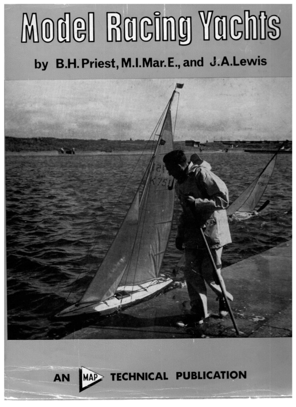
Model Racing Yachts is a comprehensive treatment of the design and sailing of competitive model yachts by two accomplished British designers and skippers, B. H. Priest and J. A. Lewis. It begins with the naval architecture of small sailing craft—displacement, resistance, keel design, stability, hull balance, lines drawing, and sail plans—and explains how these interdependent choices shape performance. The authors emphasize that model yachts cannot simply be scaled-down full-size boats: they sail in full-strength winds and must be designed to meet the distinctive constraints of model racing and class measurement rules.
The book then examines three principal racing classes—the 10-Rater, Marblehead 50/800, and International A Class—with close attention to rating rules, successful designs, and the evolution of competitive hull forms. Later chapters turn to practical tuning, on-the-water handling, and racing tactics, connecting design theory with the observations and adjustments that win races. A final chapter introduces construction methods. Illustrated with photographs, technical drawings, and nine fold-out yacht plans, the book serves as both a historical account of mid-century model-yacht development and a practical reference for designers, builders, and racers.
Preface. The authors explain their aim of linking basic yacht-design theory with class rules, tuning, handling, and racing experience, stressing the relevance of model experiments to full-size sailing.
Part One—The Naval Architecture of Model Racing Yachts
Chapter I: Introduction. Introduces the design process, the effects of racing-class restrictions, the differences between model and full-size yachts, and the interpretation of hull-lines drawings.Chapter II: Displacement. Explains buoyancy and displacement and demonstrates practical volume calculations using the trapezoidal and Simpson’s rules; also considers the longitudinal distribution of underwater volume.Chapter III: Resistance. Examines the forces that oppose a yacht’s movement through water, including frictional and wave-making resistance, and their implications for hull shape and speed.Chapter IV: The Keel as a Salient Feature. Discusses the keel as an essential part of a model yacht’s hydrodynamic design, including its influence on lateral resistance and overall performance.Chapter V: Stability and Hull Balance. Considers the ability of the hull and ballast to resist heeling and the relationship between hull form, balance, and sailing behavior.Chapter VI: Drawing the Lines. Describes the drafting and fairing of the hull’s waterlines, sections, and profiles, translating design ideas into usable construction drawings.Chapter VII: The Sail Plan. Explains sail-plan proportions, placement, and the interaction of mainsail and jib in producing efficient drive and balance.
Part Two
Chapter VIII: The 10 Rater Class Yacht. Explores the measurement rules and design choices of the 10 Rater class, showing how designers balance dimensions, sail power, and performance.
Part Three
Chapter IX: The Marblehead 50/800 Class. Reviews the Marblehead class and the development of successful 50-inch, 800-square-inch designs, including differences in hull shape and sailing characteristics.
Part Four—The International ‘A’ Class
Chapter X: Rating Rules. Sets out the rating-rule background needed to understand the design and measurement of International A Class yachts.Chapter XI: The International ‘A’ Class Rule and its Operation. Explains how the rule works in practice and how its measurement provisions influence the combinations of hull, ballast, and sail dimensions.Chapter XII: Pre-war Under the Rule. Traces early A Class racing designs and the developments that emerged before the Second World War.Chapter XIII: Post-war Development Under the ‘A’ Class Rule. Follows changes in A Class design after the war and considers how leading boats and designers advanced the class.Chapter XIV: The Development of a Design. Uses the evolution of particular designs to illustrate practical decisions, compromises, and improvements in yacht architecture.
Part Five—Tuning, Handling and Racing Tactics
Chapter XV: Tuning. Details the adjustments to rig, sails, steering, and balance used to obtain the best performance in different wind conditions.Chapter XVI: Handling. Discusses sailing and controlling a model yacht, including the skipper’s response to the boat’s behavior on different points of sail.Chapter XVII: Racing Tactics. Examines competitive decisions such as positioning, wind advantage, and encounters with other yachts on the racecourse.
Part Six
Chapter XVIII: Construction. Outlines practical methods and considerations for building model-yacht hulls and related structural elements.
Index to Fold-out Plans
Plan I: Lines of Top Hat ‘A’ Class. Hull lines for the International A Class design Top Hat.Plan II: Lines of Whirlwind 10-rater. Lines drawing of the 10 Rater Whirlwind.Plan III: Lines of Witchcraft Marblehead. Lines drawing for the Marblehead yacht Witchcraft.Plan IV: Lines of Witch Marblehead. Lines drawing for the Marblehead yacht Witch.Plan V: Lines of Bewitched Marblehead. Lines drawing for the Marblehead yacht Bewitched.Plan VI: Lines of Commando ‘A’ Class. Lines drawing for the International A Class yacht Commando.Plan VII: Lines of Saxon ‘A’ Class. Lines drawing for the International A Class yacht Saxon.Plan VIII: Lines of Highlander ‘A’ Class. Lines drawing for the International A Class yacht Highlander.Plan IX: Lines of Moonshine ‘A’ Class. Lines drawing for the International A Class yacht Moonshine.
ode] Macing VOcwnis by B.H. Priest, M.I.Mar.E., and J.A.Lewis —S �MODEL RACING YACHTS There are probably no two people better qualified to write a book on the arts of present-day model yachting than Dick Priest and John Lewis. Between them they have designed the majority of the top boats in important races in the last few years; both are outstanding ‘A’ class designers, Lewis is a top-line 10-rater architect, and Priest especially strong on Marbleheads. Thus the three main classes are completely covered by their combined experience. Practically, they are once again completely complementary, with Priest the really experienced racing man and Lewis, no mean skipper, of a highly experimental turn of mind. Both have deep sea experience, and Priest has considerable dinghy racing behind him, while Lewis has been responsible for experimental work connected with full-size sailing craft of a highly successful nature. Both build yachts, fittings, etc. As mentioned in the book, both were members of the same model yacht club for years, and worked together on research and basic design analysis, etc. While each produces individual designs, there is a similarity of conception and execution, not to mention a similarity in the long string of successes enjoyed by boats built to their designs! With such impressive qualifications, the publishers have confidence in offering this book as the finest ever written on the subject—a book which will be fascinating to any interested in the design and handling of yachts of any size, and one which will be the standard text-book for model yachtsmen for many years to come. Published by MODEL & ALLIED PUBLICATIONS LTD. 13/35 Bridge Street, Hemel Hempstead, Herts. Publishers of model books, plans, etc, and the following periodicals: Model Boats Model Cars Model Engineer Aeromodeller Model Railway News oo Radio Control Models and Electronics 49s. �MODEL RACING YACHTS Their architecture, design, construction, and handling By B. H. Priest, M.I.Mar.E. and J. A. Lewis Model & Allied Publications Ltd (13 /35 Bridge Street, Hemel Hempstead, Hertfordshire �Other Titles: RADIO CONTROL MANUAL No. 2 SIMPLE ELECTRIC CAR RACING BOAT MODELLING MODEL MAKER ANNUAL THE AMATEUR ROD-MAKER FLYING SCALE MODELS AEROMODELLER ANNUAL AIRCRAFT IN MINIATURE USING THE SMALL LATHE MODEL AERO ENGINE ENCYCLOPAEDIA POWER MODEL BOATS AEROMODELLER POCKET DATA BOOK GLASS FIBRE FOR AMATEURS SIMPLE RADIO CONTROL CONTROL LINE MANUAL VANE STEERING GEARS SECRETS OF SHIPS IN BOTTLES MULTI-CHANNEL RADIO CONTROL Further titles to be announced regularly Trade Distributors: ARGUS PRESS LIMITED 12/18 PAUL STREET, LONDON, E.C.2 PRINTED AND BOUND IN ENGLAND BY HAZELL WATSON AND VINEY LTD AYLESBURY, BUCKS �Contents Preface Part One—The Naval Architecture of Model Racing Yachts Chapter I Introduction Chapter IT Displacement 10 Chapter III Resistance 15 Chapter IV The Keel as a Salient Feature 20 Chapter V Stability and Hull Balance 22 Chapter VI Drawing the Lines 26 Chapter VII ‘The Sail Plan 32 The 10 Rater Class Yacht 36 Part Two Chapter VIII Part Three Chapter IX = The Marblehead 50/800 Class 45 Part Four—The International ‘A’ Class Chapter X Rating Rules Chapter XI The International ‘A’ Class Rule and its Chapter XII Pre-war Under the Rule Chapter XIII Post-war Development Under the ‘A’ Class Chapter XIV The Development of a Design Operation Rule 52 55 58 62 71 Part Five—Tuning, Handling and Racing Tactics Chapter XV‘ Tuning 80 Chapter XVI Handling 92 Chapter XVII Racing Tactics 102 Part Six Chapter XVIII Construction 107 �Index to fold-out plans Plan I Lines of Top Hat ‘A’ Class Plan IT Lines of Whirlwind 10-rater 40 Plan III Lines of Witchcraft Marblehead 46 Plan IV Lines of Witch Marblehead 50 Plan V Lines of Bewitched Marblehead 54 Plan VI Lines of Commando ‘A’ Class 74 Plan VII Lines of Saxon ‘A’ Class 78 Plan VII Lines of Highlander ‘A’ Class 90 Plan IX Lines of Moonshine ‘A’ Class 100 �Preface Tuts book is the endeavour of two men to describe the science of Model Yachting from A to Z, from the very basics of design, through the application of design to the various rating rules, and on to tuning and handling. The book has been written to be of help not only to Model Yachtsmen but to those who sail Twelve-Metre boats, 5:5 Metre boats, Dragons or Dinghies. This might be considered an ambitious statement and that there can be little or no connection between one who designs and sails a model and one who designs and sails a Twelve-Metre yacht. Within the book it will be found that there is in fact quite a real con- nection. Taking design for an example, as applied to the International ‘A’ Class rule, it will be realised that we have as yet less then twenty registered numbers in the Twelve- Metre Rule in the country, whilst the International ‘A’ class models are nearly up to a registered number of eight hundred. Design to a rating rule is built up from a number of interrelated curves and factors. These can be combined in an infinite number of manners. As all design is a compromise then how these factors are combined decides whether a good or a bad boat has been produced. It is often said that nothing is new in yacht design, it has all been tried before. This is, of course true, but by altering all the things that can be varied then a brand new type of design can be produced. It would be logic to assume that the model designer, in the course of the thirty odd years that the International ‘A’ Class Rating Rule has been in use, has just about tried the lot and in so doing has evolved a type of boat miles ahead of the old originals. Just how this evolution took place must be of interest to every serious designer. It might be said that the Twelve-Metre designer has the advantage of being able to have his products tank tested. This is correct, but it must be remembered that the tank will only compare, say, four different designs; it will say which of them is the best under different wind ranges. It will not, however, say whether the products are good, bad, or indifferent. All four might be bad and the tank will only find the best of a bad bunch. A great deal has been written on the magic thing called Tuning. In this field the model man has a great advantage. He is not in the boat but is able to walk alongside it and so observe its every action. Because of this he has been able to devise a most scientific approach to the whole question, so much so that his final windward tune is reduced to no more than a degree on the helm or an eighth of an inch on the sheeting trim. The authors are only too aware, from practical experience, of the problems of trying to tune a yacht when sitting in it. Under these conditions everything is confused to a degree. Is it mast position, sheeting angle, or sail flow? Is the boat being pinched or is she having to be held up on her course? All this is simple to the experienced model yachtsman. By observation alone he can tell at once which point it is that requires correction. It is remarkable how few people have the faintest conception of how to set about the tuning of a boat, or even what are the major factors to be considered. For this reason the whole subject has been set down from its basics and the writers have endeavoured to guide the reader through the subject in what they consider the correct manner. If they have done their job correctly then the obvious conclusion will be that the only correct manner to tune an America’s Cup Challenger will be by having its designer up in the air to observe its conduct during competitive trials. The authors have set about this book because they believe that there is now a need for it and, on paper, that they are the most fitted to tackle the job. They base this assumption on the fact that in the three major classes sailed in the country, boats to their designs have won each of the National Championships of these classes, at least three times in each over the last ten years. It has been of great advantage that the writers have been members of the same club for a number of years and because of this have been able to talk about their designs and ideas together in a spirit of friendship and competition. It was found that their ideas were very much in sympathy, insomuch as they agreed on all major points. It will probably be found, indeed it is more than possible, that in reading through the book a divergence on minor issues will be found. Even in design it will be found that although the type of lines drawn have quite a likeness, their proportions vary. For example it will be found as a general rule that a Lewis design. has its centre of buoyancy somewhat further forward than that in a Priest design. This can only mean that the former type of design has finer after sections than those of the latter. Lewis is known to be more concerned with the actual theory of design than his co-author who has had a more practical experience. Because of this the book has naturally split itself into the fields in which the writers have felt most fitted to write—Lewis on design and the Ten Rater rule, in which field he has had his greatest success, Priest, on the other hand, on handling, tuning, and on the International ‘A’ Class, in which he is probably best known. A vast amount has been written about the art of sailing. Read though one may, it is usually found that the real crux of the matter is always left untold. Pure experience is the thing that eventually counts and this is very hard to put down in words, even if the writer wants to. In this book it has been the intention of the writers to put on paper, in the simplest manner they can devise, all the theory and experience they have encountered. In this effort they themselves believe they have succeeded. Time alone will prove if this is so, because, if it is found that design, tuning, handling, and competition have improved, the authors will consider their efforts to have been worth the labour. DICK PRIEST JOHN LEwIs �PART ONE The Naval Architecture of Model Racing Yachts CHAPTER I Introduction THE designing of yachts is one of the most fascinating occupations that a man can have, particularly if he is not dependent on it for a living. It provides an outlet for his creative instincts and he can blend artistic and scientific talents in such proportions as pleases him. A great deal of research work is being done on yacht design but it will be a long time before designing becomes so highly technical that the man with a good eye and a feeling for a boat cannot compete successfully. He must of course be aware of developments but he need not have more than a basic knowledge of naval architecture. All yacht designs are produced to satisfy a particular specification. This may be in the form of Racing Class Rules or the requirements of the future owner. Sometimes the needs of the owner will not produce a satisfactory yacht and this is only one of the professional designer’s worries. The professional designer has also the responsibility of spending large sums of money and this is bound to check experimental development. Tank testing of sailing yacht models is interesting, expensive and provides data which can often be misleading. The designer’s brain and vision are still the most important elements of success. The model yacht designer is free of many of the restrictions of the designer of full scale craft and his job is considerably easier. He does not have to consider the con- structional problems of a design except in a most rudimentary way, he does not have to accommodate a crew, nor does he need seriously to consider seaworthiness. He can, if he is designing to one of the Racing Class Rules, concentrate all his efforts into producing the fastest form of hull to suit the particular rule. The Rule is his specification and as such must be thoroughly understood by him. He should be familiar with work of other designers and he should take every opportunity of seeing models performing under all conditions of wind and water. One of the worrying things about designing is the pendulum of fashion. When a successful yacht appears on the scene there is a tendency for the design features of that yacht to be pushed steadily to extremes by unintelligent development. If this occurs slowly the bad features do not show up until someone moves in the opposite direction and starts winning prizes. So, whilst being aware of the latest designs, also beware, and do not imitate for fashion’s sake. The basic laws of naval architecture in the determination of hull form are the same for model yachts as for large sailing yachts. There is no similarity between racing models and 8 racing dinghies or other forms of sailing craft which plane at high speeds on the surface of the water. Model yachts do in fact plane extremely rapidly but they do so under conditions in which full-size craft would not survive. The model yacht architect should look at designs of over 30 ft. length if he is seeking inspiration or guidance. Although the design process is similar it does not follow that a good model would necessarily be a good yacht if scaled up to full-size. It is equally true that success in full-size cannot be scaled down to a model. This brings us back to the importance of the initial specification. The wind does not accommodate itself to the requirements of the model designer and so his small yacht has to contend with a full scale wind. The water is also out of scale in density and due to the small expanse on which races take place it is very rare for the waves to exceed the length of a modern 10 rater or International A class model. Models have to race in wind strengths of up to 40 m.p.h. and therefore need to be extremely powerful and stable. Model races continue long after full-scale regattas cancel their events and the ocean racing chaps would be more water. concerned with survival than speed through the This does not mean to say that model designing cannot contribute usefully in the development of full-size yachts. In fact the model designer is in a position of advantage due to his freedom, and the intelligent use of his knowledge by the full scale designer could be of considerable value. This is becoming more and more recognised as a fact in yachting circles and it is a great pity that there are so few model designers who are pursuing a steady line of development towards improving design generally. A yacht to be satisfying as well as satisfactory should be a thing of beauty. Fortunately those features which produce what is acceptable as beauty fit in quite well with the require- ments of performance. The shape of a model does not have to be distorted in order to accommodate crew or passengers. It is as difficult to define what makes a yacht beautiful as it is difficult to describe why a picture is beautiful but there are certain features which can be learnt by anyone. However, it is the designer’s basic instinct for beauty of form and line which ultimately determine the final appearance. A good design does not need fashionable gimmicks to help it. The following chapters will explain various aspects of yacht architecture which are useful to the designer of model yachts. The information is treated under separate headings for simplicity but it should always be remembered that it is �ove TOP HAT DESIGNED BY John Lewis . COPYRIGHT OF MODEL MAKER PLANS SERVICE 38. CLARENDON RD. WATFORD, HERTS INTERNATIONAL A CLASS SCALE: Ye FULL SIZE. 55:0″ 81-25″ DISPLACEMENT 60:0 LBS. (46 LBS. LEAD) 14-25″ LWL. BEAM 12-2″ DRAUGHT LWL. LOA, 11-74″ (1620 CU.INS) Yo QBL AV.F 52-06″ 4-4″ S. AREA 1604 SQ INS. 40°03 SA. FULL SIZE FIGURE 2 8] BODY PLAN YACHT �SAIL PLAN va SCALE IST —25-0″ 2ND,3RD,4TH — 24-5″ | LEAD LINE —64-0″ | IST suIT 2ND. + 80-0″ 3RD. + 65:0″ 4TH. + 60-0″ 72-0″ IST. 2ND. 605″ 54.5″ 3RD. 505″ 4TH 455″ (ST -20″5 ” 2ND,3RD,4TH — 20:0″ �MODEL RACING YACHTS “Vv SNIT MOG fe} fer D c D m m 5 fe) a3 fe) fe) Zz Zz ie | aundld > fe} na i Qa Zz wo ‘@ SNIT MOG |se m > 7) wn n ay fe) fe) D no} x > =A, ol ETM. ‘@ ADOLLNG VADOLLING i t_ y 7 Z cOvid ‘DADOLLNG IMS STM. oa Zam OTM “D SNIT MOG ‘S81 O09 LNSW39DV 1dSId—O-SS “TM1 SIHL NI SANIT JO NOILD3fOUd JO NOSIYVWdWOD DINO SaTaVNA (AsioDwaxXa DNILHONVYC ONILSAYSLNI NV) YAINNWW LTA > SoS a ee i ai | The representation of the shape of a yacht hull by means of a lines drawing can be a most absorbing essay in draughtsmanship. Whilst some superb drawings can be produced it is not essential to be a skilled draughtsman as long as due care is taken and a high standard- of accuracy is maintained. As in all good drawing each individual line has a definite meaning and Figs. | and 2 illustrate how the various hull lines interrelate. In the horizontal plane the ‘Level Lines’ or what are more commonly called ‘Waterlines’ show the shape of the hull at various distances above and below the ‘Load Water Line’ (L.W.L.) which is itself the plane of flotation of the hull at its designed displacement. The ‘Buttock Lines’ show the hull shape in the vertical plane parallel to the longitudinal centre line. These lines should more accurately be called ‘Bow Lines’ from midships forwards and ‘Buttock Lines’ from midships aft. The cross sections show the transverse shape of the yacht and it is on these shapes that the most important calculations are based. _ The lines ‘indicating the shape in an inclined plane are known as diagonals and these are most valuable in quickly arriving at a truly fair hull. The projected set of lines in Fig. 1 is not particularly useful in design but it does illustrate the use of lines and gives 2) 4 m a S ee a ee ee The meaning of the hull lines drawing an Zz Dv D NAHM JIT AOOT TIM TINH VW LYHM JO NOISSAYdHI TWIYOLDId VW SAAID GNV SOLLSIYSLOVYVHD TINH the amalgamation of all the considerations which make a good or bad design and that change in one feature is bound to cause change in other features. Only the designer himself can choose just how far he is prepared to push the advantages in certain directions and thereby accept the disadvantages in other directions. The designer must decide whether he is going to limit the yacht to a good heavy weather performance, a good light weather performance, or try and produce a good all-rounder. It is much easier to design for extreme conditions than to compromise and try for excellent results at all wind strengths. The easiest design to prepare is that for a good heavy weather boat when practically everything can be sacrificed to length and power. The light weather boat is probably the most entertaining of them all, as all sorts of architectural devices can be employed in order to reduce wetted surface area and skin friction. There is no need to consider only sheer maximum speed for a given length. The differences in hull form for low resistance at high and low speeds will be dealt with in a later chapter. The most difficult design is that intended to combine good light weather and heavy weather ability. In fact it is impossible for a compromise design to equal an extreme design in its own particular conditions, and the term ‘good all-rounder’ is rather a misnomer. The compromise design will always stand a chance of being beaten under any particular conditions but whereas the extreme designs will win races under their ideal conditions they could also be well down the finishing order on many occasions. The compromise design will win fewer first prizes but may constantly be in the top four and for this reason most model racing skippers prefer the compromise with a slight bias towards the average conditions in their particular locality. The fact that a model yacht has to operate over a wide speed range makes the problem interesting and it is very doubtful whether there will ever be finality in design. In the case of powered craft, which are usually required to travel at a fixed economic speed, for a given length the hull form is more or less predetermined. �MODEL RACING YACHTS a good impression of the hull form in three dimensions. The normal layout comprises a plan, an elevation, and a set of cross-sections. In the plan the centre line, buttock lines and cross-sections appear as straight lines whilst the waterlines are curved. The elevation or profile contains the waterlines and cross-sections as straight lines and the curved lines are the bow lines and buttocks. The set of cross sections is commonly called the Body Plan but is really a.set of superimposed transverse sections. INTERNATIONAL “A” CLASS “YEOMAN” BEATING TO WINDWARD IN SECOND SUIT. GOSPORT 1952 CHAPTER II Displacement IF a yacht were to be placed in a tank which is brim full of water a certain quantity of water would spill over the sides of the tank and be ‘displaced’. Now it is a fundamental law that the weight of the displaced water would exactly equal the weight of the yacht and the volume of the displaced water would exactly equal the immersed volume of the hull. If weight is added to the yacht it will sink deeper into the water until the volume or weight of displaced water again exactly equals the new weight of the yacht and thereby also equals the new immersed volume. If more and more weight is added a condition is reached when the volume of the hull is insufficient to displace the necessary weight of water and the yacht will sink. This serious state of affairs does not occur very often but all too frequently a yacht does not float on its correct waterline plane because either the designer has made a mistake in his calculations or the builder has ignored the constructional weight set out by the designer. 10 People are often quite muddled when thinking about displacement. For example it is surprising the number who believe that filling a hull with table tennis balls would cause it to float higher out of the water whereas in fact the hull would sink lower, as its displacement is increased by the weight of the celluloid! The two most important decisions a designer has to take are in deciding what waterline length the yacht needs to be and to what displacement he shall shape the hull. As an alteration in weight will alter the depth at which the hull floats so will alter, therefore, the load waterline length. It is essential then for the designer to be able to calculate the volume of the hull below his chosen L.W.L. so that he knows accurately the resulting displacement. If the calculation shows that the displacement is different from that required, then the designer has to redraw the hull accordingly until the answer is correct. The calculation of displacement is the only absolutely �MODEL RACING YACHTS necessary piece of mathematics needed in hull design and fortunately it is easy enough for anyone to do providing one of two formulae is accepted without worrying about the derivation. The two methods most commonly used are known as Simpson’s Rule and the Trapezoidal Rule, and to illustrate the working of these rules we will run through the enon of a typical 10-rater design of 55 in. waterline ength. It is usual for a designer to divide the L.W.L. length into 10 equal parts and the body plan therefore will show the cross-section of the hull at eleven positions along the L.W.L. It is convenient to number these sections 0 to 10 starting from the bow ending. It is necessary to measure the area of each of the cross-sections below the L.W.L. and if much designing is contemplated it is well worth buying a planimeter. This instrument will enable the job to be done quickly and accurately. They are very expensive if bought new, some £14 to £25, but can often be bought for less than £3 second-hand, from pawnbrokers. Try to find a shop near a university! Failing a planimeter the areas can be arrived at by using ,4, in. squared paper as shown in Fig. 3. This is quite accurate but somewhat tedious. Having arrived at the areas of the under-water parts of the sections we can apply one or other of the rules but remember that the sections only show half the total areas and the final figure must be doubled to give the true volume. With this rule you simply take half of the area of the first and last section (usually in a yacht design these areas are zero),’total up the areas of the other sections and multiply the result by the distance between the sections. Remember to keep the units of measurement the same, i.e. inches and square inches, and the result will be in cubic inches. The figures for a typical 10 rater are as follows: 0 1 2 3 4 5 6 7 8 9 10 4 Section number Area sq. in. 0 1 2 3 4 5 6 7 8 9 0-00 1-15 5-52 9-95 14-76 20-00 16-35 9-73 5-70 2:15 10 0-00 Rule multiplier Area sq. in. 0-00 1-15 5:52 9-95 14-76 20-00 16-35 9-73 5-70 2:15 0-00 Rule multiplier – 0-5 1 1 1 1 1 1 1 1 1 0-5 Multiply by 2 for total areas. Multiply by section spacing i.e. 5-5 for actual volume. 1 lb. of fresh water equals 27-7 cu. in. Totals 0-00 1-15 5-52 9-95 14-76 20-00 16-35 9-73 5:70 2:15 0-00 Totals 1 0-00 4 2 4 4-60 11-04 39-80 2 4 29-52 80-00 2 4 2 4 1 32-70 38-92 11-40 8-60 0-00 Multiply by 2 for total areas The Trapezoidal Rule $ Section number render the use of the Trapezoidal rule inadvisable. Simpson’s Rule is more popular in this country whereas on the Continent and in the U.S.A. the trapezoidal rule is more frequently employed. It is essential that the body whose volume is being calculated is divided longitudinally into an even number of parts, i.e. there must be an odd number of sections. Using the same section numbering as in the previous example you take areas of numbers 0 and 10 and add them to the areas of 1, 3, 5, 7, and 9 multiplied by 4 and the areas of 2, 4, 6, and 8 multiplied by 2. The total is then multiplied by the distance between the sections divided by 3. 256:58 x2 Multiply by oe for actual volume 512-16 : x 1-83 = 937-25 For fresh water divide by 27°7 = “7° — 33-83 Ib, For salt water divide by 27:0 = ar = 34-71 Ib. FIGURE 3 Note. Put good quality paper divided in ‘/Oths. under area to be measured and count Tedious squares, but accurate. 85-31 x 2 170-62 x 5:5 938-41 + 27:7 mt rT Tt therefore divide by 27-7 for actual displacement — 33-87 lb. or 1 lb. salt water equals 27-0 cu. in. divide by 27-0 for salt water displacement = 34-75 Ib. Ignore squares where area is less than half Count squares where area is more than half Simpson’s Rule This rule is more complicated than the Trapezoidal rule but is slightly more accurate although not sufficiently so to Use of squared paper 11 �MODEL RACING YACHTS a good impression of the hull form in three dimensions. The normal layout comprises a plan, an elevation, and a set of cross-sections. In the plan the centre line, buttock lines and cross-sections appear as straight lines whilst the waterlines are curved. The elevation or profile contains the waterlines and cross-sections as straight lines and the curved lines are the bow lines and buttocks. The set of cross sections is commonly called the Body Plan but is really a set of superimposed transverse sections. INTERNATIONAL “A” CLASS “YEOMAN” BEATING TO WINDWARD IN SECOND SUIT. GOSPORT 1952 CHAPTER II Displacement IF a yacht were to be placed in a tank which is brim full of water a certain quantity of water would spill over the sides of the tank and be ‘displaced’. Now it is a fundamental law that the weight of the displaced water would exactly equal the weight of the yacht and the volume of the displaced water would exactly equal the immersed volume of the hull. If weight is added to the yacht it will sink deeper into the water until the volume or weight of displaced water again exactly equals the new weight of the yacht and thereby also equals the new immersed volume. If more and more weight is added a condition is reached when the volume of the hull is insufficient to displace the necessary weight of water and the yacht will sink. This serious state of affairs does not occur very often but all too frequently a yacht does not float on its correct waterline plane because either the designer has made a mistake in his calculations or the builder has ignored the constructional weight set out by the designer. 10 People are often quite muddled when thinking about displacement. For example it is surprising the number who believe that filling a hull with table tennis balls would cause it to float higher out of the water whereas in fact the hull would sink lower, as its displacement is increased by the weight of the celluloid! The two most important decisions a designer has to take are in deciding what waterline length the yacht needs to be and to what displacement he shall shape the hull. As an alteration in weight will alter the depth at which the hull floats so will alter, therefore, the load waterline length. It is essential then for the designer to be able to calculate the volume of the hull below his chosen L.W.L. so that he knows accurately the resulting displacement. If the calculation shows that the displacement is different from that required, then the designer has to redraw the hull accordingly until the answer is correct. The calculation of displacement is the only absolutely �MODEL RACING YACHTS necessary piece of mathematics needed in hull design and fortunately it is easy enough for anyone to do providing one of two formulae is accepted without worrying about the derivation. The two methods most commonly used are known as Simpson’s Rule and the Trapezoidal Rule, and to illustrate the working of these rules we will run through the pail of a typical 10-rater design of 55 in. waterline length. It is usual for a designer to divide the L.W.L. length into 10 equal parts and the body plan therefore will show the cross-section of the hull at eleven positions along the L.W.L. It is convenient to number these sections 0 to 10 starting from the bow ending. It is necessary to measure the area of each of the cross-sections below the L.W.L. and if much designing is contemplated it is well worth buying a planimeter. This instrument will enable the job to be done quickly and accurately. They are very expensive if bought new, some £14 to £25, but can often be bought for less than £3 second-hand, from pawnbrokers. Try to find a shop near a university! Failing a planimeter the areas can be arrived at by using ,’, in. squared paper as shown in Fig. 3. This is quite accurate but somewhat tedious. Having arrived at the areas of the under-water parts of the sections we can apply one or other of the rules but remember that the sections only show half the total areas and the final figure must be doubled to give the true volume. lated is divided longitudinally into an even number of parts, i.e. there must be an odd number of sections. Using the same section numbering as in the previous example you take areas of numbers 0 and 10 and add them to the areas of 1, 3, 5, 7, and 9 multiplied by 4 and the areas of 2, 4, 6, and 8 multiplied by 2. The total is then multiplied by the distance between the sections divided by 3. } Section number Area sq. in. Rule multiplier Totals 0 0-00 1 1-15 1 0-00 2 4 2 + 2 4 2 4 1 11-04 39-80 29-52 80-00 32-70 38-92 11-40 8-60 0-00 2 3 4 5 6 7 8 9 10 4 5:52 9-95 14-76 20-00 16-35 9-73 5-70 2:15 0-00 4-60 Multiply by 2 for total areas The Trapezoidal Rule With this rule you simply take half of the area of the first and last section (usually in a yacht design these areas are zero), total up the areas of the other sections and multiply the result by the distance between the sections. Remember to keep the units of measurement the same, i.e. inches and square inches, and the result will be in cubic inches. The figures for a typical 10 rater are as follows: % Section number render the use of the Trapezoidal rule inadvisable. Simpson’s Rule is more popular in this country whereas on the Continent and in the U.S.A. the trapezoidal rule is more frequently employed. It is essential that the body whose volume is being calcu- Area sq. in. 0 1 2 3 4 5 6 0-00 1-15 5°52 9-95 14-76 20-00 16-35 7 8 9 10 9-73 Rule multiplier 0-5 1 1 1 1 1 1 . 5-70 2:15 0-00 1 1 1 0-5 Multiply by 2 for total areas. Multiply by section spacing i.e. 5-5 for actual volume. Totals 0-00 1-15 5-52 9-95 14-76 20-00 16-35 256°58 x2 Multiply by x? for actual volume 512-16 3 1-83 = 937-25 For fresh water divide by 27-7 = 37° _ 33-83 1b. For salt water divide by 27:0 = — = 34-71 |b. FIGURE 3 Note. Put good quality paper divided in ‘’Oths. under area to be 9-73 measured and count 5-70 2:15 0-00 Tedious squares. but accurate. 85-31 x 2 170-62 x 5-5 938-41 1 Ib. of fresh water equals 27-7 cu. in. S21 therefore divide by 27-7 for actual displacement = 33-87 Ib. or 1 Ib. salt water equals 27-0 cu. in. divide by 27-0 for salt water displacement = 34-75 lb. TT mt Tt Ignore squares where area is less than half Count squares where area is more than half Simpson’s Rule This rule is more complicated than the Trapezoidal rule but is slightly more accurate although not sufficiently so to Use of squared paper 11 �MODEL RACING YACHTS Thus it will be seen that the results are very close and that the Trapezoidal rule withits simple arithmetic is good enough for all practical purposes. All the preceding remarks on displacement are referring to measured displacement under static conditions. As soon as a boat starts to travel forwards various dynamic forces come into play and in the case of very fast motor boats and hydroplanes the displacement is reduced to very small amounts. The normal buoyancy forces are replaced almost entirely by dynamic forces supporting the hull. When model yachts are planing in strong winds their actual displacement is reduced although their weight remains the same. For this reason the terms displacement and weight are not synonymous. The choice of displacement is dealt with in later chapters but remember that the heavier model yachts have been the most successful and that light displacements although very attractive have a number of disadvantages. The Curve of Areas Although it is vital for a designer to know how much a hull is going to displace he should also consider how that displacement is to be arranged in the available waterline length. He can concentrate it mostly in the middle part of the hull and have relatively sharp ends to the boat or he can distribute the volume as much as practicable into the ends of the hull. In the first instance he will be thinking in terms of a light weather yacht and in the second instance he will produce a hull with a high maximum speed most suitable for hard weather sailing. This particular issue will be dealt with more fully under discussion of speed and hull form. The graphical way of demonstrating how the displacement is distributed is to draw the curve of areas of displacement. A typical curve is shown in Fig. 4 and it will be seen that a base line A.B. is divided into 10 equal parts and vertical lines are drawn from each of the division points. These lines are known as ‘ordinates’. Number the ordinates in exactly the same way as the section numbering of the lines plan and measure along each ordinate the amount of the section area used in calculating the displacement of the hull. If the points so obtained are joined up with a fair curve the resulting figure will show the pattern of displacement distribution. The area of the figure will also be equal to the volume of the hull providing consistency has been maintained in the use of measuring units. At one time this displacement curve was thought to have great significance and it was a widely held belief that the curve should take the form ofa sine wave for its first part and. a trochoidal curve for its after part, this combination of curves being similar to the natural shape of a wave and the belief was known as the ‘Waveform Theory’. In actual fact there is no theory involving geometry of line or mathematical deduction which has any fundamental value to the design of sailing yacht hulls. For the model yacht designer the curve of area has value when used for comparing one hull form with another. The modern form of design has a distinct fin keel and it is more useful to omit the displacement of the keel when drawing the curve as it will otherwise tend to distort the shape around the midship section. Fig. 5 shows the curve of areas of the canoe bodies of the A class yachts Top Hat and Vital Spark superimposed on the sine wave and trochoidal form. It will be seen how much modern designs differ from the old theory. USING A PLANIMETER TO MEASURE THE BODY SECTION AREAS OF A DESIGN �ae 4 3 7 pa 7 6 =a 4 FIGURE 5 RATERIO FARE SOFCURVETYPICAL 4 5 FIGURE 7 6 MODELSCLAS AOFARE SOFCURVES SPARK. ‘VITAL MODEL RACING YACHTS 5 13 �MODEL RACING YACHTS INTERNATIONAL “A” CLASS “CONCORD” 1934. SPORTING THE OLD TYPE OF SAIL PLAN WITH SMALL JIB AND LARGE MAIN. the same way as before and using the Trapezoidal rule the set out is as follows: Section number Area/sq.in. Moment multiplier Moments ote 0 1 2 3 4 5 6 7 8 9 10 0:00 1-15 5-52 9-95 14-76 20-00: 16:35 9-73 5-70 2:15 0-00 0 1 2 3 4 5 6 7 8 9 10 Sum of areas 85:31 Sum of moments 432-24 x distance between sections 0:00 1-15 11-04 29-85 59-04 100-00 98-10 68-11 45-60 19-35 0-00 432-24 5:5 = 2377-320 Divide product of moments and section spaces by the 2377:32 sum of the area: sar 7 27.86. The centre of buoyancy lies in a vertical plane 27-86 in. aft of the forward L.W.L. ending. Finding the Centre of Buoyancy Prismatic Coefficient To express it simply the Centre of Buoyancy is that point at which the volume of the underwater part of a hull would exactly balance if the shape of the volume were made in some homogenous substance. It is particularly important to know the position of this point in a longitudinal direction as the designer must arrange for it to coincide with the centre of gravity of the structure. In actual fact the two centres will automatically arrange themselves in the same place but if the designer or builder has made a mistake the yacht will either float bow down or stern down. This unhappily occurs too frequently to be amusing and is usually due to the materials of construction being differently arranged or of different density from that expected by the designer. No two yachts, either large or miniature, work out exactly the same and it is probably true to say that all designers are a little worried until they have seen the hull afloat. Fortunately for the model designer the centre of gravity of a hull tends to work out very close to the centre of buoyancy and it is a waste of time doing elaborate calculations to find the C.G. The calculations for finding the centre of buoyancy are quite simple and for an example we will use the same hull as for the displacement calculation. The cross-sectional areas are measured and tabulated in A measure of displacement distribution can be made by examining the proportions of a hull in terms of the midship sectional area, the length and the volume. The most useful formula is: 14 Volume of immersed part of hull L.W.L. x area of immersed midsection This is known as the Prismatic Coefficient and it will be appreciated that a hull of fine ends and large midship section will have a lower coefficient than one with full ends and a proportionally small midsectional area. There is a scale of coefficients said to be ideal for any particular speed but the yacht designer cannot make much use of this as his design has to contend with a very wide speed range. For low resistance at higher speeds a high prismatic coefficient is desired and it will be seen that for a given waterline length a light displacement hull can have a higher coefficient. It is probably true that for model racing yachts the prismatic coefficient should be in the range of 0-5—-0-6. The lower figure is about the highest that can be achieved in the rather heavy A class without incurring penalties’in other directions and 0-6 is a good guide for lighter 10-raters but there is little need to go higher. The actual figure for Vital Spark and Top Hat is 0:5 in each case. �CHAPTER III Resistance THERE are three forms of resistances which conspire to prevent a model yacht from travelling as fast as we would wish: (a) Eddy resistance (b) Wave resistance (c) Skin friction The least important of these from a design point of view is the eddy resistance and it is obvious that there should be no sharp corners in a design. Eddies are set up wherever the flow of water leaves the surface of the hull due to an abrupt change in shape. It is the duty of the builder to make sure that trailing edges of keels and rudders are as sharp as possible and it was once the practice to sheath these edges in some full-size craft with metal in order to achieve this end. Now that satisfactory adhesives are available it might be worth while gluing metal strip to these edges in models and to sharpen them to a greater degree. It is attention to all details that add up to a really successful model. One of the most prolific causes of eddy resistance is the frequent slipshod construction of skeg, rudder post and rudder. In model yacht design eddy resistance is usually ignored but it should not be forgotten entirely. It cannot be completely eliminated and eddies must be induced in a yacht when sailing to windward as the whole hull and keel is pushed through the water at an oblique angle. Furthermore, hull shapes satisfactory in full-size design can cause eddy resistance in a model where none existed on other larger yachts, the waterline endings at the stern being a case in point. In certain racing classes it is possible, and desirable, from the rule cheating point of view to end the waterlines in a very abrupt curve. This curve is of sufficient radius to allow nevertheless a smooth passage for the water, but scaled down to model size the equivalent radius can be so tight that water will no longer flow smoothly and eddies are set up and the resistance of the model will be unduly high. Thus an advantage in full-size may be a disadvantage when using the same rating formula in miniature. A racing model requires easier lines than its full-size counterpart. Speed/length relationship and wave making resistance Before delving into the subject of wave making resistance it is necessary to consider how the relative speeds of different hulls can be assessed. It is of no value to say that a boat is fast merely because it can travel at a certain speed. Speed must be related to length in some way and it is a convenient fact that the length of the waves set up by the hull in motion, being determined by the particular combination of speed and length of that hull, can provide us with a basis for fair comparison. In about 1870 William Froude started a series of experiments with model hulls and was able to produce his laws of comparison. He established that when a ship and a model of it move through the water at such speeds that the speed of the model is to the speed of the ship as the square root of the length of the model is to the square root of the length of the ship then the waves set up by each are of identical pattern and the two can be compared on a fair basis. The velocity of a wave in water is proportional to the square root of the length of the wave, so that as the length of a ship’s wave when travelling near its maximum speed is roughly equal to the length of the waterline of the ship, we can compare the speeds of different vessels by looking at the factor _¥ VLWL where V is the speed in knots and L.W.L. the waterline length in feet. For example, a yacht with a waterline length of 36 ft. travelling at 6 knots has a speed/Iength ratio of a = 1-0 THE DANIELS DESIGNED “SERICA’? PROBABLY UNDER-CANVASSED FOR HER SIZE IN LIGHT CONDITIONS �MODEL RACING YACHTS greater share that skin friction has on the overall considera tion. It is often the case that a heavy boat has less wette: SPEED RATIO I-3 SHALLOW HULL FORM SPEED RATIO 1-3 DEEP HULL FORM WAVE FORM OF YACHT FIGURE 6 Likewise an ocean liner 900 ft. on the waterline travelling at 30 knots also has a speed/length ratio of 1-0. Thus the express liner is just as slow as the sailing yacht when length only is taken in consideration. For a normal displacement type hull a speed length ratio of 1:3 is rarely exceeded and ratios of 1:0 to 1:1 are much more common. Above 1-3 the wave length set up by the hull begins to exceed the L.W.L. and special types of hull form have to be considered for these higher speeds. Not very much reliable data is available for the actual speeds of sailing yachts as there are so many variables in type and in condition of sailing. It is known that powerful sailing yachts do achieve a speed ratio of 1-5 but it is probable that the average speed of a racing yacht is less than 1-0. With models the picture is somewhat different due to the scale effects of wind, etc. and speed/length ratios of above 1-0 are much more readily reached. Therefore a racing model may be designed to suit a higher average speed than its equivalent full-size craft. This is one more reason why a good model does not necessarily produce a good large craft. It is all a matter of compromise as the racing boat has to be of lower resistance than its competitor over the complete speed range. From the argument emerges the basic of all truths in yacht design that in order to obtain speed the most important single factor is the length. For this reason most rules govern- ing racing yacht design control length by some means in the formula. Usually an increase in length has to be paid for by a reduction in sail area. It is the designer’s choice as to how far he can increase the length before the sail area becomes too small to drive the yacht reasonably well in light winds. It should not be forgotten that when we speak of the velocity of waves we are talking of the velocity of a motion. The water itself does not move forward but merely goes up and down in the same place. To be strictly accurate the particles of water described earlier orbit but there is no general progression in the direction of the wave. Whilst the length of the wave is related to its velocity so is the power needed to generate a wave related to its height. For a given waterline length a heavy displacement hull will produce a deeper wave formation than a light displacement hull and it will require considerably more power to drive it at a given speed. For this reason a long light hull will have a higher potential speed than a shorter heavier one. However, the resistance of the longer hull may be considerably greater than the shorter heavy boat at the lower speeds due to the 16 surface and it is one of the reasons for the apparent parado: that the heavier boats perform better in light airs. This ha been proved time and time again in racing results both full size and model; only the designer can decide just what ar the best proportions of length and displacement to suit hi particular needs. This is why it is so important for a designe to observe yachts performing under all conditions and t have a broad knowledge and understanding of othe designers’ work. Having selected a length and weight the designer will bi concerned with producing a hull of minimum midship cross section and with the displacement spread out towards thi ends of the hull as far as practicable. He will also endeavou to keep the hull shallow rather than deep as the shallow hul produces a flatter wave formation and is also more easil! persuaded into a planing action when driven very har« down wind. All these factors add up to a high maximun potential speed but also they cause the light weather ability to suffer. I _ There are sensible limits in hull form beyond which a de signer should not go, For example, a hull designed for th: higher speed ranges may have quite adequate performance in light airs but if the high speed characteristics are pushec even further the result may well be only an infinitesimal im provement in top speed and complete ruination of ligh weather ability. It is not possible to set a limit and a designe: should be allowed to make his own mistakes in this respect 1932 AND THE LATE BILL DANIELS WITH “ANGLIAN” emer: �MODEL RACING YACHTS What would be true for one designer would not necessarily follow for another as it is the designer’s individual concep- tion of the vessel as a whole which is important, not the elaboration of any single feature on its own. Closely allied with the resistance of a hull due to simple wave making as a result of length and displacement, is the rather more complicated consideration of hull form. In other words, how should the displacement be distributed within the waterline length? We have already said that the higher speeds are achieved by spreading the volume of the hull towards the ends, but how much should be in front of the midship section and how much should be aft of this point? Here again the model yacht designer has an easier job than if he were designing a large vessel. There are three basic hull types: (a) Cod’s head type (b) Wedge type (c) Symmetrical type The cod’s head type of hull is that which has a larger proportion of its displacement situated before the midship section than aft. This gives very full waterlines forward and a beautifully buoyant bow. The after lines of the hull will be quite fine and smooth. The type has some attraction and for a time was popular with full-size designers. Tests have shown however that the resistance of this type is only lower than the other two at very low speeds when there is practically no wave-making resistance. This rules the type out as far as the model designer is concerned. At least it does so assuming that no radical development is about to occur in sail plans. Should it become possible to use large genoa jibs on a model then the fuller and more buoyant bow may well be superior. A genoa sail has considerable depressing action right where a yacht has least reserves and to be able fully to utilise this sail could well result in higher speeds despite the greater resistance of the hull. Consideration of resistance should never allow the designer to ignore the power available in the sails and a number of well known and very successful ocean racers are designed in this way. It may well be that due to the success of these boats it will become fashionable to have LW.L.PLANS OF SYMMETRICAL AND WEDGE FORM HULLS L.W.L. INTERNATIONAL “A” CLASS “SHALIMAR” IN 1953. BRITAIN’S CHOICE IN THAT PERIOD TO CHALLENGE FOR THE Y.M. CUP IN U.S.A. this hull form and we shall see the type wrongly used in classes where the genoa sail is not allowed! The wedge type of hull with fine waterlines forward and full lines aft is also a traditional type. The old waveform theory of displacement distribution inevitably had its effects in this direction butall things considered it is a good hull form for full-size yachts. Problems of seaworthiness and pitching action worry the full-size designer and the fine slicing bow is an attraction to many who have to sail in choppy water. The hull can have ends which are distinctly dissimilar and this damps out pitching motion to some extent. There is also the advantage that the type provides adequate support for a crew weight concentrated in a cockpit near the aft ending of the L.W.L. These three advantages are of no consequence to the model designer and can be thoroughly ignored. He is only concerned with sheer speed and at high speed/length A. WEDGE FORM ratios too. The wedge type has the highest value of resistance at very low speeds but the situation quickly changes as soon as wave making starts. From about 0-5 to 1-0 speed/length ratios the type has the lowest of all three. Above this speed the symmetrical hull form is slightly superior. However, as soon as the model is forced into semi-planing conditions the wedge form probably is again superior. B. SYMMETRICAL FORM FIGURE 7 M.R.Y.—2 The disadvantage from the model designer’s point of view is that the wedge type is not so readily ‘balanced’ as the 17 �MODEL RACING YACHTS symmetrical. This feature will be discussed more fully in a later chapter. The symmetrical hull form is the best for the racing model as the resistance at low speed is less than the wedge type, is distinctly less than the cod’s head type, greater than the wedge type at medium speeds (only very slightly) and has slightly less resistance at the higher speeds in which models most frequently operate. As in all things a compromise usually works out best and the most successful model yachts are of symmetrical general form with their centres of buoyancy slightly aft of midships. Therefore the model designer’s job is relatively simple; he chooses length and displacement, decides whether he is designing for maximum speeds or medium speeds and spreads the displacement accordingly, arranging at the same time for the centre of buoyancy to be midships or slightly aft. It is as simple as that! There are other refinements which can be studied. For example, if the forward waterline endings are made somewhat more blunt than the actual L.W.L. a lowering of total resistance can result. This is a nicety of design but it is doubtful whether these tiny modifications to a basic hull shape can actually be detected in the performance of a racing model. They mean much more to potential America Cup challengers where every detail must be perfect. One of the sad things about model yachts is the need for high displacements in order to obtain power and stability. This makes the wave making resistance a most important issue, fortunately simply dealt with, but, nevertheless, inhibiting radical development in design as a whole. Uffa Fox has been quoted as saying ‘Weight is only useful in a steam roller’ and up to a point this has some truth in large yachts generally, is absolutely true when applied to planing boats and has no truth whatever when applied to models as we at present know them. Over the years the displacement of model yachts has grown and grown, the sail areas have become smaller but all the time the average speeds have gone up. In the International A class and 10 rater classes the design compromise has probably been reached during the last 5 years. The 6 Metre class is now virtually ignored but is very much undeveloped in model form, the International M class is such a poor rule that it is valueless from a design development point of view. We now await new advances in materials and sails. These things can themselves cause a change in hull style and choice of basic dimensions. Skin friction It is obvious that a hull with a rough surface will have a higher resistance than one that is smooth. What is not obvious is the degree of smoothness necessary to obtain worthwhile benefits. An examination of skin friction problems can be most interesting as we soon find that it is not just a simple matter of smoothness but the question of shape and form have to be brought back into the argument. To put the problem into perspective we know that at a speed/length ratio of 1-0 the total resistance of a hull is 50 per cent due to wavemaking and 50 per cent due to skin friction and eddy making. Below 1-0 and at about 0:5 the skin friction can account for as much as 80 per cent of the total. Above 1:0 the wave-making resistance begins to increase very rapidly in proportion but the skin friction does still increase with speed. Naturally a reduction in skin friction at higher speeds will contribute little in the matter of increased speed but at medium speeds it is very important indeed. For the full-size designer skin friction is one of his headaches; he can design the wetted surface to be as small and as long as practicable but otherwise he is helpless. He is dependent on the owner keeping the yacht clean and free from marine growth. The model yacht designer however can design into his boat flow characteristics which will assist in reducing skin friction and which can be maintained during the life of the model with reasonable care by the owner. There is great scope for development in the field and here is one place where the model designer may be of considerable help in full-size development. To appreciate the full implication of skin friction we must look more closely into the mechanics of the flow of water. If we consider the flow of water past a surface to be built of extremely thin layers we can imagine that the layers close to the surface will be travelling at a lower velocity, than the layer some distance from the surface. The change in velocity relative to the surface will be from zero immediately in contact with the surface to the speed of flow some distance away. The thickness of water in the state of changing velocity is known as the boundary layer. If the surface is perfectly smooth, in an academic sense, then the flow past the surface is said to be laminar and is of the minimum possible resistance. It is not easy to achieve this theoretical perfection HOWARD NASH 0O.B.E. AND “FANTASY” IN NOTE THE PRE-VANE ERA TYPE OF SKEG AND RUDDER 1935. �MODEL RACING YACHTS but at low speeds with a very smooth surface and with a helpful shape of body much can be done. Very small imperfections of the surface will destroy the laminar flow and turbulence is set up, the degree of turbulence being approximately proportional to the magnitude of the roughness. The greater the turbulence the greater is the . frictional resistance. It is possible to have a condition where laminar flow exists in the boundary layer very close to the surface and turbulent flow in the remaining thickness, but as speed increases the laminar flow will break down and the flow will be entirely turbulent. It is easier to maintain a laminar or transitional flow condition when the water is tending to impinge on the surface rather than tending to diverge from it. A model yacht, although often travelling at a relative speed higher than its full-size counterpart, spends much of its time at quite low actual velocities. Thus it is more reasonable to expect laminar flow conditions to be main- tained on a model than on a larger vessel. In fact if models were only about 12 in. long when travelling at speed/length ratios of around 1-0 it could be expected that the flow be entirely laminar! Laminar flow causes difficulty in tank testing procedures at low speeds and test models have to be fitted with studs or WAVE MAKING RESISTANCE INTERNATIONAL “A” CLASS “YEOMAN” DEMONSTRATING THE USE OF A SMALL SEMI FLAT SPINNAKER FOR RUNNING IN A FRESH QUARTERING WIND RESISTANCE wires on the hull to try and destroy this condition which would never be achieved in full scale. Many bad mistakes SKIN FRICTION -~ FIGURE 8 were made over this phenomenon in early testing and this is one of the reasons why commercial tests are carried out with models as long as many full-size yachts. Laminar flow then is a function of smooth surfaces, low speeds and favourable shape. Skin friction is reduced in first consideration by reducing the total area, without destroying other desirable performance characteristics, making the surface as smooth as possible bearing in mind the possibilities of laminar flow with super smooth finishes, and area for area making the surface longrather than short. The model de- signer can then spare a thought to making the shape, particularly of the keel, more prone to laminar flow. He should. not forget though, that these shapes offer higher resistance under turbulent conditions and if the surface is not going to be super smooth then he had better not experiment. These remarks on laminar flow are something of an over simplification and if the designer is sufficiently interested he should study a good book on hydraulics. 19 �CHAPTER IV The Keel as a Salient Feature DuRING the past fifty years the most noteworthy development in yacht design has been the progressive way that the keel has emerged as a salient feature. We have now reached the stage where the keel can be regarded as a separate functional unit and its reaction on the canoe body design is relatively unimportant. At any rate this is true as far as the model designer is concerned although it will be seen later that a heavy displacement canoe body should be associated with a different fin keel from that for a light displacement canoe body. Model yacht designers have been in the van of this development and we now see quite a number of full-size designs with the fin and skeg combination so long ago proved successful in model work. It is realised that the fin keel has the most important part to play in promoting efficient sailing on a windward course and that the hull proper has relatively little to contribute in this respect. The forces acting on a sailing boat when sailing to windward are shown in Fig. 9 and it will be seen that in order to prevent a wholesale movement sideways it is the lateral resistance of the keel that checks the movement and permits the yacht to travel forward. The resistance generated by the fin keel is not only due to the pressure on the leeward side of the keel but also due to a lowering of pressure on the windward side caused by the water flow around it. In this respect, and many others, the keel can be likened to an aeroplane wing in its action. In order to produce the ‘lift’ the keel will take up a certain angle relative to the direction of flow of water. The angle is called the leeway angle and is the reason why a yacht does not travel in the direction it is looking! The amount of the angle, which can also be called ‘angle of attack’, is dependent on a number of factors such as: WIND DIRECTION LEEWAY ANGLE FIGURE 9 DIRECTION OF WATER OVER KEEL ACTION OF KEEL WHEN SAILING TO WINDWARD 20 (a) (b) (c) (d) The The The The area of the keel aspect ratio, i.e. the depth/chord ratio cross-sectional shape of the keel speed The increased efficiency that development has produced in keel design has enabled the total area to be considerably reduced. This is very fortunate because the more salient keel inevitably increases the wetted surface of the yacht on a given displacement. Only by drastic modification of the profile shape has the total area been kept within reasonable limits. Nevertheless there is a tendency for modern yachts to have a poorer light weather performance than older vessels due to increased skin friction. This is taking due consideration that older boats usually carried more sail as well. The criterion of design for an efficient fin keel is that it shall have a high lift and a low drag. This is normally refer- red to as the lift/drag ratio and it is generally accepted that a narrow chord and a great depth will produce the best results. This is all very well up to a point and now we have to consider the practical difficulties and compromises necessary. As well as depth and chord the keel must have thickness. All other things being equal a thin keel has been proved to provide a good lift/drag ratio superior to that of a thick cross-section. On the other hand, when a very heavy displacement hull is under consideration it may be worth while permitting an increased thickness of keel to absorb some of the displacement. This will make it possible to have easier lines and perhaps less resistance in the canoe body. The thicker keel will also allow the lead ballast to have a lower centre of gravity. Obviously this will make the yacht more stable and she can be driven harder. This is particularly important in model designing. These advantages may in some instances outweigh the disadvantages of a lower lift/ drag ratio. In the author’s experience thick keels do not benefit the model designer and they are best avoided. However, this does not mean that useful experimental work cannot be carried out in this direction. From tests already made with several model racing yachts it would seem that the higher resistance of the thick keel is only apparent when going to windward and that there is little difference when the yacht is sailing before the wind with no angle of leeway. If we now swing to the other extreme and consider a really thin keel we come up against the difficulty of finding room for the lead ballast. Why use lead? Gold, platinum, uranium, and a few other precious metals are available if you have the money. Mercury is not so expensive but is rather difficult to handle but why not put it in a plastic bag heat sealed and inserted into a hollow fabricated fin keel? �MODEL RACING YACHTS Even resort to these limits will not allow keel thickness to be ideally small, particularly if the designer wants to have a small chord. For model work it is advised that the thickness be somewhere in the range of 8 per cent to 12 per cent of the chord. This automatically sets a limit on the chord for all practical purposes and means that very high aspect ratios are not feasible. This is not so serious as may be thought at first, as area for area a high aspect ratio of keel gives a higher skin friction than does one of lower proportions and it is a noticeable trend that models with deep narrow keels aresomewhat sluggish despite perhaps a lower total wetted surface. The choice of cross-sectional shape for the keel is important but not much factual information is available to help the designer. It is usual to employ a symmetrical aerofoil as shown in Fig. 10(a). This indicates a maximum thickness some 30 per cent back from the leading edge and a fairly blunt form of entry. Fig. 10(b) shows something generally similar but with a sharp entry. This has found favour with a number of designers but the very sharpness of the leading edge is open to criticism. When in condition of flow with an angle of attack the sharp edge could set up eddies which may break down the steady flow over the windward surface and thus induce increased drag and loss of ‘lift’. Fig. 10(c) shows another section which has been used successfully and it will be seen that the maximum thickness has been moved back to some 45 per cent of the keel chord. This type of section probably has virtue in being more prone to laminar flow conditions. It would be very interesting to carry out a whole series of tests using different keel sections under a constant canoe body design’ The designer should make himself familiar with the range of modern aerofoils published in various journals, particularly those of the N.A.C.A. This is a field wide open to research and the model designer can make a worthwhile contribution, providing his experiments are well reasoned and well conducted. We are now naturally led into consideration of total fin keel area necessary for good performance. It has been suggested that the area of keel can be related to sail area but this leaves out the effect of speed on the lift/drag ratio. When moving slowly a yacht cannot generate proportionately as much lateral resistance for a given area as it can at higher speeds. If there is insufficient area the angle of attack increases and likewise does the drag so that we can now see the difficult state of affairs the designer is in. For light weather windward ability he requires a large keel area for low induced drag but he also requires a minimum total wetted surface for low skin friction. At higher speeds he can reduce the lateral area but as wave-making absorbs so much power from the sails he does not gain very much by doing so. The type of canoe body needs to be considered at this stage. If the yacht is of heavy displacement and deep cross-sectional form it should not be asked to sail at high angles of attack. The resistance of such a hull being driven obliquely through the water is bound to be excessive and it is better to suffer the penalty of too much keel area and the associated skin friction. The penalty will be paid when running and reaching in light airs. If the hull is of light displacement and flat cross-sectional form it may. well be that the induced drag due to the greater obliqueness of travel will not be greater than the reduction in ars due ‘to the small keel area and a benefit is possible. However, whilst we are designing canoe bodies of generally symmetrical shapes it is probable that the angle of attack TYPICAL CROSS SECTIONS OF KEELS — A. ROUND NOSE —- ra 30Z0F CHORD a B. SHARP NOSE C. SHARP NOSE MAX.WIDTH 457 OF CHORD ZMAX.WIDTH SO7 OF CHORD D. LAMINAR FLOW PRONE SECTION FIGURE 10 should be kept to a minimum. Should the design trend be towards extremely small keel areas then it may well be that the canoe body will need to be of different type. This presupposes a general reduction in displacement of models and leads one into the realm of catamarans and other types which do not achieve stability by weight alone. It is therefore preferable to have too much lateral area than too little for good all-round performance. On consideration of satisfactory ballast C.G. and the resultant effect on keel chord we have an immediate guide for the allowable depth of keel or total draught for the model. This seems to work out at between 11 in. and 13 in. for the three most popular racing classes, i.e. International A, 10 rater and International M. The fact that draught is limited by the Class rule in A class makes the job easier for the designer. The profile of the keel is discussed lastly as it probably is the least important although it will be the first thing the designer draws. Having decided what approximate area the keel shall have and accepting a greater chord than we would really like in order to accommodate the lead we see that there are only two sensible alternative profiles. There is the basic parallelogram or a smooth flowing shape of considerable artistic merit. From a sheer efficiency point of view the parallelogram should be superior and is the one usually adopted these days. The chord is greater where the lead is needed and the relatively constant cross-section should contribute to a good performance. On the other hand two of the finest designers in the world nearly always adopt the smooth flowing type, of profile without apparent loss in speed and ability. There is more in this question than meets the eye and keel design is by no means fully understood. The positioning of the fin keel under the canoe body is one of compromise but one in which the practical considerations outweigh theory. The leading edge of the keel will have a slope of usually 45° to 55° and this means that with a centre of buoyancy just aft of midships it is not practicable to put the lead right across the bottom of the keel without placing the whole appendage too far forwards. It will be too far forwards because it is necessary for the sail plan to be situated in a relative position to the keel. If the keel goes forward so must the sail plan and this cannot be carried to excess 21 �MODEL RACING YACHTS aon WL Nccnone \) 45/55) oad USUAL LEAD BALLAST LINE A. RECOMMENDED TYPE OF PROFILE B. PROFILE OF FLOWING LINES C. FULL KEEL TYPC FULL KEEL TYPE OF REDUCED WETTED SURFACE achieved. In order to compensate for this some designer, like to thicken the cross-section of the keel and form a sor of bulb to take the lead. With a normal type of profile thi: should not be necessary and could easily reduce the overal keel efficiency. Some years ago there was violent argument whether o1 not the rudder should be placed on the aft edge of the kee or whether it should be hung on a separate skeg further aft Practical tests settled the issue, as far as models are concerned, in favour of the separate skeg arrangement. The advantages seem to be principally in the greater contro] and directional stability achieved and less tendency to wander off course when sailing to windward with variable angles of heel. It is also possible to design with less wetted surface area but one must not ignore the fact that a number BALLAST HIGHER mR CU D. MODIFIED These limitations on keel positioning force the lead t be concentrated towards the leading edge of the keel anc gives a somewhat higher C.G. than would be otherwis i FIGURE 11 KEEL PROFILES without performance limitation. It is also desirable that the thickest part of the keel be placed under or very near to the deepest part of the canoe body. This enables a much more satisfactory blending of the two shapes in the gar- boards. of very successful full keeled models have been produce d. Strangely, though, these have not been of British design. It is possible that, with the knowledge now availabl e, the full keel type may still have a future. The increased wetted surface may be offset by the production of laminar flow. The keel being of great chord can be relatively thin and still accommodate the lead very low down. The full keel will not need a high angle of attack and the induced drag of the hull will be low. Providing the rudder post is vertical and well aft there should not be undue difficulty in achieving adequate control. However, until a designer has some considerable experience he is advised to concentrate his efforts on the conventional fin and skeg types. The keel areas and proportions shown in the various designs in this book are the result of much thought, experi- ment and intense competition racing. It is signific ant that there is nothing radical about them. CHAPTER V Stability and Hull Balance Very fortunately for the model yacht designer he has no need to carry out the tedious calculations determin ing stability which are so often required with large vessels. We know that generally speakinga model yacht cannot be too stable and that this stability is derived from two sources. Firstly, the ballast in the keel should be as high a percentage of the total displacement as possible, and its centre of gravity should be as low as possible. The two factors are linked with the initial choice of dimensions and the design of the fin respectively. The second source of stability is derived from the shape of the hull in cross-section. We have already discussed the position of the Centre of Buoyancy in a fore and aft direction but it must be obvious that this position can also be located in a vertical plane. For most yacht designs it is not necessary to make this calculation but the shape of the 22 canoe body will determine the actual height. The C.B. must be positioned in exact line over the C.G. when the yacht is upright. However, when the yacht heels the C.B. will move outwards in the direction of keel. This produces a righting couple which resists the force causing the heeling action. A vertical line drawn through the C.B. will cross the centre line of the hull at a point known as the Metacen tre. The height of the Metacentre can be taken as a guide to the stability and this position is sometimes used to analyse the characteristics of a hull when trying to achieve ‘balance’. The amount by which the C.B. moves is determi ned by the shape of the hull and the greater the moveme nt for a given angle of heel the greater is the inherent stabilit y. Thus a deep narrow hull will have less stability than a wide flatter type. The fact that a flatter type of hull also has a higher potential speed sometimes leads the designer into the mistake of excessive beam and flatness. It must be remem- �MODEL RACING YACHTS bered that the wide flat form, although possessing consider- able initial stability, may well have less stability at large angles of heel than a more moderate form. Similarly, the wide hull will usually have a higher resistance, when sailed at angles of heel, than a deeper type on the same displace- ment. If a model could be sailed in an upright attitude in the same way as are racing dinghies the whole aspect of model yacht design would be changed. A further advantage of the narrower hull is that it can usually have the least wetted surface area. All these points have led to the tendency in model yachts for them to be both narrow and of fairly flat form. In order to obtain the required displacement the turn of the bilge is somewhat low and is distinctly rounded and full. This type has proved to be very successful but it is not necessarily so good when applied to full-size design. Hull Balance A yacht is said to be ‘balanced’ when it shows no tendency to wander off course during varying angles of heel. There has been more controversy over this aspect of design than any other. There is no simple answer to the problem but it is absolutely necessary for a model to be directionally stable. Things are not so critical for the full-size yacht as there is nearly always a helmsman ready to provide the necessary rudder correction and it may well be that a well balanced yacht is not necessarily the fastest. This is a penalty that the model designer must be prepared to pay as there is no point in having a very fast yacht that often speeds in the wrong direction! It has been said that a few degrees of weather helm is a good way of improving windward ability and this is true. It is not, however, necessary to cater for this condition at the design stage as it can be achieved by proper trimming and tuning if so desired. There are many influences which will try to alter the course of a model yacht when sailing. It is easy to visualise the force of the wind on the sails causing the yacht to heel. The force acts at a point on the sail plan called the Centre of Effort. This centre is normally considered to be at the centre of gravity of the sail plan and is easily determined. Unfortunately the centre of effort moves forward or aft depending on the wind strength and the trim of the sails. However, it will be seen that when the yacht is heeled the transverse position of the centre of effort will not be in line with the water forces on the hull itself and a slewing or turning action is produced. This has to be resisted by the hull and fin. The fin when resisting the sideways force of the sails does so through a point called the Centre of Lateral Resistance. This point can also be calculated and is the centre of gravity of the under water profile of the yacht. In a similar manner the Centre of Effort of the sails, the C.L.R. moves from the calculated position as soon as the yacht moves through the water. The actual position varies according to the speed, angle of attack, cross-sectional shape and the profile up into irons, head to wind. Model yachts are fitted with means to alter the mast position over a range of about 3 in. and this makes it quite easy to arrive at the best position. It is probable that many full-size yachts could benefit from a mast movement but this is rarely done due to expense and trouble, furthermore the effects of a wrongly positioned sail plan are so often concealed by the helmsman. This position of the sail plan can be used to correct other forces acting on the hull which we have not yet discussed. These forces should be eliminated if possible by good design rather than having to be counterbalanced. However, the forces of the sails can only be dealt with by counterbalance methods. The designer can help himself to a limited extent by not designing keels of exotic shape so that the movements of the C.L.R. are reasonable. For example a very steep leading edge to the fin tends to cause luffing at high angles of heel and it is not recommended that an angle of 45° be exceeded until considerable experience is obtained. s 7 CO oS SL} Z/ NO Ce SS / A BALANCED HULL SHEWN IN SOLID LINE eee UNBALANCED « > eee « ” “ FIGURE 12 – y oN) shape. The turning forces produced by the sails through the centre of effort have to be counterbalanced by the hull forces acting through the centre of lateral resistance. Both these forces move in a way which cannot be usefully calculated, therefore the designer is left in a pretty pickle. He has only one course and that is to guess at the correct positioning of the sail plan over the hull. If the sail plan is too far forward the yacht will not point up into the wind, and if the plan is too far aft the yacht will be constantly going 23 �SRR SSS SSS SSS SS SSS a ea error MODEL RACING YACHTS FIGURE 13 identical. If this type of hull is ever proved to be the fastest all-round performer then the design of model yachts will cease to have any interest! F ortunately this is most unlikely. ‘ LW.L. A. UPRIGHT The similarity of the ends of the hull really comes about from the need to avoid a change of fore and aft trim on heeling. If the Centre of Buoyancy moves aft the stern will rise and the yacht has a strong tendency to gripe or shoot up into the wind. Conversely if the C. of B. moves forward then the yacht will head off the wind. It*is better for the C. of B. not to move at all up to angles of heel of 25°. This of course presupposes that there will be no other forces on the hull which will cause an unbalanced effect and which therefore need to be counteracted. For example, in designs with a full or long keel it is possible for the flow of water to Cause a pressure on the keel surface well behind the C.L.R . and this pressure can cause the hull to turn. Usually this effect is for the garboard stream to be trapped on the lee- ward side of the keel and the yacht tends to turn away from the wind. This can be offset by allow ing the C. of B. to move aft on heeling by some prede termined amount. To judge the actual movement necessary is one of extreme nicety and the designer has no guidance in the matter. He can only make a guess. It is far better therefore to avoid such effects and this is one of the main reasons that the fin and skeg is so satisfactory in model form. CENTRE OF LATERAL RESISTANCE AND CENTRE OF EFFORT B.HEELED RIGHTING MOMENT TRANSVERSE MOVEMENT OF C.B.ON HEELI NG It is in the design of the hull that the designer can do most to avoid unbalance in the completed yacht. Certainly if the canoe body is of the wrong form then nothin g at all will make the yacht a good racing model. Many fine brains have been applied to this problem to try and devise a geometric way of drawing the lines so that balance is automatically achieved. None of the theories so far promulgated are completely satisfactory. The most famous one is Admiral Turner’s ‘Metacentric Analysis’ and althou gh yachts designed to this method are undoubtedly docile and easy to handle they are not necessarily fast. The great success of his racing model design does not lie in the compli ance with his theories but rather with his foresight in choice of initial dimensions. He was the first model design er to see the advantages of heavy displacement. Now that other designers have gone further than the Admiral dimensi onally, his _ yachts are being beaten by models not design ed by the use C.OF E.OF Jip LW.t> : e of his method. The common factor which emerges from all hull balance considerations is that the ends of the hull should be similar in character. They do not have to be identical as in the tyP€ known as the ‘Circular Arc’ form. With these hulls the profile and cross-sections are all based on the arcs of circles and it is inevitable that both ends of the canoe body are 24 CENTRE OF LATERAL RESISTANCE = THIS DISTANCE CAN ONLY BE DETERMINED BY EXPERIENCE AND EXPERIMENT FIGURE 14 ESSE �MODEL RACING YACHTS HEELED LW.L. *IN’WEDGE ‘ouT’ WEDGE do nothing about but we do know that a hull which is unbalanced when checked statically will certainly be unsatisfactory in actual practice. There is no guarantee, though, that any yacht of fresh design will be docile or balanced despite all the designer can possibly do. More often than not a new design is developed from a previous one of known characteristics and the designer is able to judge with more certainty what effects his modifications will have. There are many unknowns about sailing yacht hulls and it is a pity that yachts are such useless things that no really big sums of money and brains will be devoted to adequate research. On second thoughts, is it a pity? When all is known and the understanding of that knowledge can only be accumulated by the very brainy, something will be lost to the ordinary mortals. Club conversation and argument about the merits of particular craft will not be possible and a new topic will need to be found. Perhaps one of the big attraction of yachts is their uncertainty and the mumbojumbo which surrounds their design. IN AND OUT WEDGES FIGURE [5 “MOONRAKER II”? SHOWS THE GREAT WINDWARD It will be seen from the diagram that when a hull heels a ‘wedge’ of the cross-section is immersed on the leeward side and another wedge on the windward side merges from the water. If the area of the ‘In’ wedges is added to the crosssectional areas and the area of the ‘Out’ wedges is subtracted we can recalculate the centre of buoyancy and observe the movement. It will also be apparent that if the upright C. of B. is approximately at 50 per cent of the L.W.L. then the ends of the hull need to be quite similar. If however the C. of B. is well aft in the upright attitude then the ends can be dissimilar and the hull can be generally of the wedge form. The big difficulty in balance comes when the designer tries to produce a wedge-type hull with the C. of B. midships or a symmetrical hull with the C. of B. aft. These shapes are possible but they will never produce a balanced design. Trying to design a very flat run aft also runs the designer into difficulty. It should be obvious that if the C. of B. moves aft the ‘In’ wedges in the after part of the hull need to be reduced in area and the ‘In’ wedges in the forward half need to be increased in area. Usually a compromise is necessary and the ‘out’? wedges have to be correspondingly modified. This also will alter the shape of the L.W.L. plane. It does not require much practice before a designer can sense whether his initial lines will produce a balanced hull and the experienced man hardly needs to check whether the C. of B. does in fact move. The amount of movement permissible has been quoted from time to time and varies from author to author. However, it is the opinion of this author that on an L.W.L. of 55 in. the C. of B. should not move more than 0-02 in. aft and it should never move forwards, on 25° angle of heel. These checks on the C. of B. only apply when the hull is in a static condition and when sailing at angles of 20° heel or more there is a considerable amount of wave-making. The hull is subject to dynamic forces which the designer can POWER OF THE TURNER DESIGNED MONSTERS IN A FRESH BREEZE �CHAPTER VI Drawing the Lines BEFORE any work on design can be started, other than rough freehand sketches (and many ideas never get beyond tihs stage), it is necessary to have acertain amount of equipment. As with most things a job can be done so much more pleasurably and perhaps a little better if the facilities and equipment are adequate. Of course a lot of good work has been done under very difficult conditions and with very meagre instruments but if it is intended to produce more than an occasional design then the following list of articles should be purchased: (1) A drawing board 54 x 32 in. is about the most useful size and as they are expensive it is worth trying to buy a secondhand one. Alternatively a piece of blockboard can be used as it is not necessary to have the usual straight edge down one side. The board should be covered by one or two layers of best quality cartridge paper. Ideally this should be shrunk and glued on but Terry clips are reasonably satis- factory. (2) A really good ebony edged straight-edge at least 48 in. long is essential and only the best is good enough. The whole accuracy of the drawing depends on this as waterlines have to be quite straight and parallel. It is better to plot the spacing of these lines rather than try to use a large T-square. (3) One 10-in. celluloid 45° set-square. Here again make sure that the 90° angle is truly a right angle, as it is surprising how often these instruments are inaccurate if a cheap one is bought. (4) One set of Dixon Kemp pear-shaped curves. They are made specially for the Naval architect and with them the job of fairing up a set of cross-sections becomes quite easy. The ordinary types of French curve are quite useless for yacht designs. (5) A set of splines and spline weights are well worth their money. The splines are usually made of lancewood but celluloid ones are also available. Splines can be tapered in thickness in various ways so that they take up a characteristic curve, but the most useful are: + X 7 tapering to 7 x i x 60 in. leng is x $ is Xt g x $ SET_OF FIVE DIXON MAHOGANY SCREWED LEAD 7 KEMP CURVES’ BASE TO SPLINE WEIGHT 5 REQUIRED Sy Wa TERRY SPRING CLIP FIGURE 16 26 99 t x $ ” 48 in. » §X a», 48in. 29 $ x as 29 36 in. ” ,, 29 Spline weights are expensive but can be quite easily made as shown in Fig. 16. The lead should be covered with some soft material such as leatherette, as uncovered it is too dirty to handle. Five such weights are required, although more are sometimes useful. However, it has been said that a curve requiring more than five should not appear in a yacht design and this has some truth when a comprehensive set of splines of all shapes and thickness is available. It is possible to manage with 4-square balsa wood held down with pins but very great care is needed to obtain an even curve. The use of splines requires a deal of practice and patience. WEIGHT ”° 5 29 (6) A planimeter is invaluable and we have already mentioned this instrument in an earlier chapter. The only scale required is a direct reading in square inches. Some instruments are adjustable on the scale arm but even if the design is half full size it is easier to multiply the readings by 4 than to readjust the planimeter from the direct scale setting. (7) Paper, rather obvious but most important. There are a number of advantages in using a transparent detail paper for the design as prints can be taken off without having to do a tracing. One can also superimpose drawings one over the other and make direct comparisons of lines. This is a �MODEL RACING YACHTS a i USE OF SPLINE WEIGHTS FIGURE 1|7 most valuable feature as so often one design is a development from another. Paper is bought in 25-yd. rolls and it is a good thing to have plenty in stock as there should be no excuse for not throwing anything away which is not completely pleasing to the designer. (8) Anaccurate scale rule and a good 12-in. steel engineer’s rule are required. (9) The last instrument needed is a good pair of 6 in.-long dividers for transferring measurements from one view of the plan to another view. Some people like to use ‘tick strips’. These are strips of paper which can be placed on the drawing and marked on the edge each time a dimension is to be transferred. There is some merit in this but dividers used with skill are much quicker in the long run. Other facilities enjoyed by the author and thoroughly recommended are: (a) Asecond small drawing board for sketches and body plans. (6) A permanent position for the large board so that one is not constantly getting up and putting away. (c) Plenty of reference books to hand. (d) Good lighting. (e) A tolerant wife who is able to give an opinion as to the fairness of lines. Before any work on the drawing board is started the designer will have made up his mind as to the general dimensions of the yacht. He must have settled on a L.W.L. for the particular class concerned and he will know whether the displacement is to be heavy or light. This means he will have to have a good idea of the figures for L.W.L. beam and the depth of the canoe body. Usually a design is developed from the experience gained in previous work but in the first instance the beginner is well advised to have a close look at other designers’ work and examine the general proportions of various yachts. There is no point in starting work on the drawing board until the design is almost completely formed in the mind of the designer and do not forget that the design includes the sail plan as well as just a hull. The first actual lines to put down on paper are the set out of the waterlines and sections in the profile view, the waterlines and buttock lines for the cross-sections, and the centre line, buttocks and sections in the plan view. All these lines are straight and should be drawn with great care. If the waterlines, for example, are not exactly parallel it will never be possible to obtain a truly fair set of hull lines. It is convenient to set the lines out at a scale of half full-size and this gives sufficient space on the size drawing board recommended. Although half size is adequate for the body plan of an A-class yacht it is better to draw the body plans of the other smaller classes to full-size. The profile should be sited exactly above the deck plan and the body plan can occupy spare space either to the right or left of the profile view. Remember to leave enough room for operation of the planimeter arm so that it will not run off the board during displacement calculations. The L.W.L. will be divided into 10 equal parts and this determines the spacing of the section lines. It is becoming common practice to divide the L.W.L. into 8 equal parts but if this is done intermediate sections should be drawn at the final stage of the design so that the builder will have sufficent information for his building shadows or templates. The spacing of the waterlines is not important but it is usual to use 1-0 in. for model work. In some instances g-in. spacing is adopted as this is often the thickness of timber used by builders who employ ‘bread and butter’ construction. A plank of wood 1-in. thick usually finishes down to 7 in. and using this spacing the builder can take off his plank widths directly from the drawing. The drawing should clearly state the section spacing and the waterline spacings. 1957 “HIGHLANDER’S” WINDWARD ACTION IN A 30 KNOT WIND �MODEL RACING YACHTS WU 10 LW.L. Fig. 18 shows the layout for a typical design with a tentative midship section profile and deck plan already drawn. Sometimes a published drawing shows the body plan turned on its side the between profile and deck plans. This is done to save space and reduce cost of the reproductions and is arranged this way when the designer’s original paper is traced. When a designer has his work published he is rather dependent on the accuracy of the tracing made from his original by the publisher for it is not often that a designer has time to do all his own work in this respect. Having put the basic construction lines down on paper the next step is to consider the shape of the midship section. There are a few basic types and an infinite number of variations of them. Fig. 19 shows a variety of types and re zZ 5 0 Ee ws 2 low S 6eé a na . O . they all have their particular merits. Pp The flat floored rather beamy type of section as typified Bow by Glengarry in the ‘A’ class and the old 10 rater types ee Oes BO Gee ine produces a very fast hull when sailed at small angles of eye “a: . : heel. It has great initial stability due to a high metacentric WME Oa oFuS Ba 1 and a potentially high speed. Unfortunately the type has inevitably a high wetted surface and light weather performance suffers somewhat. Furthermore, when heeled the shape of the L.W.L. changes quite considerably and this can mean an increase in resistance. Due to the large ‘In’ wedge the hull tends to lift out of the water on heeling and this offers considerable windage which spoils the windward performance and also reduces the effective lateral area of the keel. Lastly, the stability decreases rapidly at large angles of heel. Thus it can be seen that the ‘scow’ type of section is only satisfactory when sailed in an upright attitude and in moderate to fresh winds. The section therefore is more =) Ba height. The shallow body gives a shallow wave formation y suitable for full-size craft of dinghy type than for models. The narrow, deep-bodied hull, as a contrast, exhibits to a large extent the opposite properties to the scow. The first y advantage of this type is the lower wetted surface for its displacement and a good light weather ability can result. The deepness of the hull however sets up a very deep wave formation when travelling at higher speeds. The resistance of such a hull will prevent it from having the potential high maximum speed of the scow type. The stability of the deep narrow hull is not great at small angles of heel but it increases progressively as the heel increases. The sail-carrying power in high winds is thus quite considerable. Mention has been made of the area of ‘In’ wedges and if a model can be shaped so that it does not lift out of the water on heeling a potentially higher speed to windward can be obtained. This is due of course to the maintenance of a long waterline length rather than a shortening of the L.W.L. – | This can be achieved by having a small ‘In’ wedge and a large ‘Out’ wedge. It is extremely fortunate that this idea LW.L , a TENTATIVE MID. SECTION |} ek yt 4 i; also fits in with the model designers’ wishes to have a narrow beam and flat floor combined with a heavy displacement for the L.W.L. in question. It is no coincidence that the authors’ most successful designs, Sirocco in the 10 rater class and Highlander in the ‘A’ class, employ this type of midship section and both of them have won their respective national championships twice. Fig. 20 shows the mid- ship section of these two yachts superimposed and it is interesting to note that the 10 rater is 1 in. longer on the L.W.L. than the A boat and its displacement is 18 1b. less! Tests in full-size craft have shown that this type of crosssection is not the fastest and this is probably due to the higher speed ratios and the need for greater stability in the model. �MODEL RACING YACHTS |_\ ee e 13 ‘ 2 rH POS | | IN 2 Q) z 2 i at a Qq-| 2 I FIGURE 19 L Jaw W, NN SW 29 �MODEL RACING YACHTS FIGURE 20 A CLASS HIGHLANDER a“ 10 RATER SIROCCO \ a MIDSHIP SECTIONS OF HIGHLANDER AND SIROCCO SUPERIMPOSED Having drawn a tentative midship section we can now consider the profile of the yacht. Three points are already established, i.e. the L.W.L. endings and the depth of the canoe body at the middle of the hull. Whether or not this is to be the greatest depth of the canoe body has yet to be decided. The points which need to be considered in this respect are whether the designer is going to try and achieve an extremely flat run aft to the hull by pushing the greatest body depth forward. If this is carried to excess it becomes difficult to achieve good hull balance and it may also be difficult to fair the keel into the hull smoothly. The curves towards the bow tend to become steep and it is not easy to obtain a respectable length of forward overhang. It is suggested that for a first design the maximum depth is positioned actually on the midship section. Using a spline which is gently tapered towards one end and with the thick end towards the stern an attractive sweep through the three known points can be drawn. The curvature aft will be less than forward and this gives the desirable flat run to the hull quite automatically. The curve between sections 4 and 6 should be virtually symmetrical and just about on section 1 the spline can be allowed to spring straight so that the bow overhang is not too short. It is almost certain that the beginner will have, quite with- out thinking, drawn the curve so that the yacht is pointing towards the left of the paper. This is not the usual practice of professional architects who almost without exception draw their lines pointing to the right. It is a peculiar fact that the natural thing to do when drawing almost anything is to face the object to the left and as this comes naturally it is suggested that the conventional practice is ignored. When the profile is drawn, however, just turn the paper the other way up and view the drawing from the back. You will be surprised as to how different the yacht looks and you may well be tempted to alter some of the curves! Having swept this first curve through the waterline endings it is necessary to decide on the length of overhang at each end. This will be influenced to some extent by the amount of freeboard and the boldness or otherwise of the sheer curve. The freeboard may be decided by the class rules, as in the International A class, or be without restriction as in 30 the 10 rater and M-class. A good look at other designs will give the beginner a guide as to how much is acceptable. There is no point in having too much freeboard, and remember that a narrow hull needs less freeboard to avoid immersing the deck edge at a given angle of heel compared with a beamy hull. The sheer curve itself is very important aesthetically. Except for the ‘A’ class which insists on a concave curve, a straight line is probably the most logical for a racing machine as it provides height midships where it is needed and limits the height at the ends where it is doing no useful job. The designer must decide how much he is going to let cold logic influence his works and whether he will accept a minute difference in performance for the sake of making his creation beautiful. When the hull is viewed in the solid a straight sheer looks as though the hull has droopy ends and as if the ship has a broken back. It requires quite a pronounced concave curve to avoid this effect and if the beginner wished to make his yacht good looking then he should give more curvature than he really thinks is correct! This applies particularly to the lift towards the bows. Examination of lots of drawings by famous yacht designers is probably the best way of judging the degree of curvature necessary. The other point to watch is that the minimum height of freeboard occurs just forward of the aft waterline ending and this is further aft than one would expect. Drawing a good sheer curve requires a great deal of practice and critical examination. It is best to use a heavy-sectioned spline for the job with the ends forced upwards slightly against the natural spring of the wood. With the sheer curve drawn we can now complete the overhangs at each end. At the bow a Dixon Kemp curve will produce a satisfactory shape but the curve should be in character with the rest of the yacht. It is not good to marry a long spikey overhang with a full sectioned hull and a selection of shapes is shown in Fig. 21. The stern of the yacht can be completed in a variety of ways, none of which has any great influence on performance. These are shown in Fig. 22. The most difficult type is the pointed or canoe stern and, if this is adopted, considerably more rise to the sheer should be given. The deck line is also more difficult to get attractive and once again a close �MODEL RACING YACHTS examination of other designers’ work is the best way to learn. William Fife designed the most attractive pointed sterns of all. The other forms of counter profile are easy enough and the model designer does not even need to draw out the developed shape for the builder as does the full-size designer. The keel profile can now be established, bearing in mind what has been written in previous chapters. Make the keel too large in area rather than too small and choose a quadrilateral shape. You can’t go very far wrong if you copy the designs in this book to start with but after the first couple of boats have been built to your drawings and have been satisfactory, you then have the basis to start experimenting. One of the joys of designing your own yachts is the freedom to try out your own ideas. The deck plan will now receive attention and in the first attempt it may help the beginner to draw the complete plan rather than just the half plan usually shown on lines drawings. So far we have only two points to guide the curve, i.e. the bow ending and the width at the midship section, and although we know the length of the stern overhang we have still to decide the width of the counter to establish the ending of the deck plan. The counter width should be kept narrow unless some difficulty in hull balance is not to be avoided. It is fairly obvious that a broad stern will promote large ‘In’ wedges aft and cause a movement of C. of B. on heeling. The maximum width of the deck can either be actually on the midship section which is quite acceptable or somewhat further aft. The usual practice is for this width to be about half way between sections 5 and 6 but this decision is influenced by the designer’s wish either to tend towards the wedge form of hull or the symmetrical form. It is probably helpful in some ways to put the maximum deck beam just aft of the midship section as this will in its turn tend to bring the C. of B. a little aft also and make positioning the C.G. of the ballast less difficult. Using the same tapered spline that we used for the profile the deck curve is now drawn. The thick end of the spline should be towards the stern as before. The most common mistake made is to draw the line too narrow towards the bow and this should be guarded against. The curve should be an even sweep through the point of maximum beam and its width at the forward waterline ending should only be slightly less than at the aft waterline ending. If it has been decided to plan the maximum beam of the deck aft of the midship section it is necessary to indicate on W.L. A, SUITABLE FOR SCOW TYPE OF HULL B. SUITABLE FOR the plan where the maximum beam of intermediate waterlines shall be. This is simply a straight line joining the point of greatest body depth and the greatest beam on deck. The maximum breadth of the waterlines must lie on this line. Similarly the greatest depth of the buttock lines must also be indicated so that a truly fair set of lines is produced. In elevation the line of greatest depths is not straight but starting from the point of maximum body depth it sweeps through a curve whose shape is influenced by the flatness or otherwise of the midship section, the actual position in a fore and aft direction of a particular buttock being determined by the projection of the point where the buttock crosses the maximum beam line in plan. The actual depth of the buttock at that point is defined by the sweep of the buttock line itself. The load waterline is the next important line to be drawn and we only have three fixed points at this stage, i.e. the endings and the width at the midship section. The shapes which can be drawn are of course infinite and in this shape the performance characteristics of the yacht are established. In models we wish to make the hull fairly full in the ends and it has been found that the half angle of entry to the L.W.L. can be as high as 33°—beyond this it is not wise to go and this figure may be taken as somewhat extreme. The angle that the L.W.L. makes with the centre line at the after end can be anything between 45° and 90°. For a first design it is better to keep the angle nearer the small figure, otherwise excessive fullness of the stern will result. Once again a good look at many other designs will indicate the variations possible in waterline shape. At this stage the line should be considered somewhat tentative as it is quite likely that small alterations will be required during the general fairing up process. A complete set of tentative cross-sections are now required and providing that no unusual form of hull is being attempted it is surprising how accurate these can be with some practice. The point to remember is that the character of the midship section is maintained from end to end. The use of the Dixon Kemp curves helps greatly in this but one should guard against becoming a slave to a particular combination of curves. From these tentative sections it is possible to draw the quarter beam buttock and make alterations where necessary to ensure that where lines intersect in plan they do so in the appropriate position in elevation and cross-section. Particulary aft, the quarter beam buttock should be almost parallel to the profile line with only slightly more progressive rise towards the end of the L.W.L. It is now not a bad idea to run the planimeter round the sections and see if the displacement is near to the figure intended. A check can also be made on the ‘In’ and ‘Out’ wedge areas to see if the centre of buoyancy moves to any V SECTION HULL A. TRADITIONAL COUNTER PLWL. C. RATHER SHORT FOR DISPLACEMENT TYPE BOW OVERHANGS FIGURE 21 Cc. CANOE TYPE STERN OVERHANGS B. TRANSOM TYPE D. REVERSE TRANSOM FIGURE 22 31 �MODEL RACING YACHTS extent. It will be remarkable if everything is alright but this check will show in which direction alterations need to be made and a lot of tedious re-drawing of lines can be avoided at a later stage. For all intents and purposes the designing stage is now complete. The rest is simply mechanical drawing and it is only necessary to put in sufficient diagonals to intersect the cross-sections not adequately dealt with by the waterlines and buttocks. After say four diagonals are drawn it will be found that the remaining lines fall almost automatically into place. Every designer develops his own preference as to the order in which he draws the various lines for fairing up, in fact some only use the diagonals, ignoring the waterlines and buttocks. Making sure that all is fair and true and at the same time producing the shape intended is a matter of careful patient work and lots of practice. The fin keel presents little difficulty once the shape of longitudinal cross-section is decided and provided a reasonable profile is chosen. It is also worthwhile drawing in some extra vertical cross-sections to help in fairing up and to make calculation of the lead ballast more accurate. The shape of the lead ballast can only be determined by trial and error and the two things which have to be fairly accurate are the total weight and the position of the centre of gravity in a fore and aft direction. The designer can only assume an approximate position for the C. of G. of the hull construction excluding ballast and therefore he is very dependent on the builder to ensure that the final trim of the yacht is correct. Generally speaking with a model carrying a vane steering gear the C.G. of the hull will be slightly aft of the C. of B.: it will therefore follow that the C.G. of the lead ballast must be correspondingly forward of the C. of B The extent to which this applies is of course dependent or the actual position of the C.G., but the point is that if the C.B. is approximately at midship it will be necessary to have the C.G. of the lead further ahead of the C.B. than if the C.B. was say 2 in. aft of midships. The actual weight of ballast is more easily determinec but here again although the designer can specify the con structional weight of the yacht all too often a builder doe: not adhere to them and blames the designer for inaccurat« calculation. It can be assumed that the all-up weights o various class models, excluding lead ballast, lie between thi following figures. M class 10 rater A class 6 to 7 lb. 9 to 10 lb. 13 to 15 lb. The weight and C.G. of the lead is calculated by usin; the trapezoidal rule in just the same way as described fo displacement and C.B. calculations. The density of the leac can be taken as 6:3 oz. per cu. in. and it is wise to cal culate the ballast to be about 2 lb. heavier than the fina assumed figure. This tolerance will then take care of thi following variables: (a) lead varies slightly in density (b) the workmanship of the foundry man (c) the accuracy of the pattern (d) it enables the C.G. to be adjusted to obtain the correc trim of the yacht. It is thoroughly recommended that a model yacht b checked on the measuring tank before the final coats o paint are applied. CHAPTER VII The Sail Plan THE model yacht designer has little difficulty in deciding the type of sail plan to use and the rating rules encourage him in the right direction. The choice is obviously the Bermudan Sloop. One should not, however, presume that this rig will remain the fastest possible in the light of research that is going on at the present time. It will be necessary, though, for the rating rules to be modified before any further worthwhile advance can be made by the model yachtsman and until then we must make the best use of things as they are. The first thing to be considered is the total area available and not a single square inch of sail area should be lost due to carelessness either in design or rigging. Each class rule has its own restriction on allowable sail area and the available total should have been considered at the same time as the decision on L.W.L. and displacement. In the case of the M class the area is fixed at 800 sq. in. measured in a certain way; in the 10 rater the area is reduced as the L.W.L. is increased with no limits set as maximum or minimum and in the A class the formula is somewhat more complicated but again the area is modified by L.W.L. and displacement. The A class also sets a maximum height to the rig which should change the viewpoint of the designer from the normal 32 consideration of ‘what is the maximum sail area I can pu over this type and size of hull’ to ‘what is the best hull I cai put under this sail plan ?’ This statement leads us directly int: the discussion of height of rig and what is commonly calle: aspect ratio. This is a widely misused term and we prefer t refer to luff/foot ratio which is the number of times th foot will divide into the luff. It is generally accepted that a tall narrow sail will hav greater driving force to windward than a low long foote: sail, area for area, and whereas some years ago a sail o luff/foot ratio of 2 was common, ratios of 3:5 to 4-0 ar now quite acceptable. One must not go wild on this heigh business, however, because for down-wind sailing a squar sail is probably the most satisfactory! Therefore one ca see that when the rating rule fixes the maximum height of rig the designer must decide on the optimum luff/foot rati and settle the area in that way. Of course, if he knows the his design will be used mainly in light air he will allow th area to be larger even though slightly less efficient than if h knows that the boat will be used where strong winds pre dominate. In this case he can cut the sail area by reducin the length of the foot without great loss of driving force an �FIGURE 24 FIGURE 23 SAIL PLAN OF ‘A’CLASS \ AT 1475 SQ” \ , AND 1600 SQ. \ BASE OF FORE-SAIL _ \ \ . INCREASES FROM 21 TO 23” . AND MAIN-SAIL FROM 23:2’ TO 27-5” ti — / NORMAL AND ULTRA HIGH ASPECT RATIO MAIN SAILS. BOTH SAILS ARE EQUAL AREA AS MEASURED BY RULE AND HAVE SAME CURVATURE IN ROACH ULTRA HIGH SAIL GAINS AN EXTRA 38SQ° FREE M.R.Y.-—3 33 �MODEL RACING YACHTS NOTE STRAIGHT LINES LEACH BETWEEN BAT TENS TO MUST NOT CURL AVOID CURLING a FIGURE 25 FIGURE 26 provide a long powerful hull to cope with the rougher condi- of the sail. One often sees the leach curling and thus disturbing the natural flow of the air as shown in Fig. 25. This is hopeless and a sail which does this should be thrown away. One of the reasons for this happening can be greed over the free area and it might be a good thing if sails were cut so that the back is a straight line between the battens as shown in Fig. 26. In these days of sailing with loose-footed sails and very tight kicking straps a heavy strain is put on the leach and the natural thing is for it to curl if the shape is exaggerated. The next question to vex the designer is to proportion the areas of jib and mainsail correctly. The use of the 85 per cent of the fore triangle measurement for the jib does tend to lead one into making the jib as big as possible so that the greatest advantage is got out of the rule. Furthermore, as the size of spinnaker is based on the fore triangle dimensions, a big jib also means a big spinnaker. Now whilst it is probable that, years ago, jibs were not big enough, the author is now satisfied that the proportions illustrated in various designs in this book give the optimum results. Experience has shown that very large jibs cannot be carried successfully by model yachts. The large spinnaker is also a snare and delusion and a properly cut small sail is better than a big bag hanging on the mast. It is also a mistake to try and fill too much of the fore triangle with sail, particularly at the head. It must be obvious that the jib has a considerable effect on the way that the air flows across the mainsail. It can either be helpful or harmful depending on the cut and setting of the jib. Ideally the air should flow off the jib, through the gap between the leach of the jib and luff of the mainsail and tions. In this way the sail area of successful A class yachts can vary from 1,475 sq. in. to 1,650 sq. in. To wander outside these limits makes the yacht too much of a single purpose vessel. In Fig. 23 can be seen the superimposed sail plan of two A class yachts. In the 10 rater and M class there is no limit to height except in the fore triangle. The law of increased efficiency with increase of height is one of diminishing returns and the designer must be careful if he wishes to exceed a luff/foot ratio of 4-0. As the height increases so does the length of the mast and therefore its weight increases and so does the height of its centre of gravity. This can have a serious effect on the sail carrying power of the hull and a increase in luff/foot ratio can result in a reduction of overall performance. On the other hand, assuming the amount of free un-measured sail area hidden in the leach of the sail is limited by a 3-5 in. roach, the increase in free area by having a very high rig can be considerable. Fig. 24 shows a normal 10 rater sail plan for a boat of 55-0 L.W.L. and superimposed is an extremely high sail plan of the same area as measured by the rule. The increase in free area amounts to 38 sq. in. As far as the author is aware such a high rig has never been used in the 10 rater class but in the U.S.A. some Marbleheads have been so fitted. The stability question is one which requires careful thought but developments in this direction may be worth pursuing with 10 rater of 60 in. L.W.L. and 35 Ib. displacement. Whilst discussing the ‘free’ area available in a sail we should remember that the battens are limited in length by the rule and this prevents too much curvature being put into the back 34 �MODEL RACING YACHTS across the leeward surface of the main in a smooth uninterrupted manner. If the gap is too narrow or the angle between the jib and mainsail incorrect the air off the jib can flow into the luff of the main, causing backwinding and considerable loss of drive. Fig. 27 shows this situation. If things are arranged correctly the jib can exercise a very beneficial effect on the mainsail and in the past this effect has been likened to the slot on an aeroplane wing, which stabilises the airflow and delays stalling. This analogy should not be taken too literally, but it does help to illustrate the point. One should remember that, contrary to usual belief, it is difficult to have the gap or slot big enough and one of the reasons is that a normal racing hull does not have sufficient beam for proper sheeting of the jib. If the rules would allow such a thing it would be helpful to move the luff of the jib to windward! It will also be fairly obvious that if the actual sail area is taken close up into the top of the fore triangle it will not be possible, no matter how the jib is sheeted, to form an adequate gap to release the air. It is bound to be very turbulent and backwind the mainsail. Therefore this is another case where greed for sail area can in fact reduce the performance of the yacht. Unfortunately no one can yet be sure just how big the gap should be, but it is quite likely that existing rigs could be modified in this respect to some advantage. When the wind blows on to a sail it causes the material to bend and form an arched surface. This is in many ways similar to the curved surface of an aeroplane wing and we know that the greatest propulsive effort is derived from the leeward surface of the sail when the velocity of the air stream will be greatest. In order to obtain the highest efficiency the camber of the sail should be greatest when the wind is light and least when the wind velocity is high. The sail maker _—<> =< BACKWINDING OF MAINSAIL DUE TO JIB FIGURE 27 bered that different types of yacht can carry different amounts of flow in the same wind strength. For example a 14-ft. International dinghy can have proportionately much greater flow than say an International 12-metre, the big difference between the two yachts being their angle of leeway. A very close winded 12-metre must have sails which are comparatively flat. This same distinction may be made between model A class yachts and 10 rater models. The 10 rater can have greater flow in this case, but the difference exists also within a particular class. For example, Highlander and Vital Spark, illustrated in this book, can have fuller sails than any other A class shown. WALTER JONES’ FAMOUS ‘A’ CLASS ‘‘SHALIMAR’’ AT FLEETWOOD therefore cuts the sails accordingly and to a very large extent indeed the yacht designer is dependent on the sailmaker’s skill and the owner’s willingness or otherwise to spend money on a number of different sails of the same size. It is perhaps no longer good enough for the designer to decide sail dimensions and then leave the rest to the sailmaker. The yacht designer should not only show the outline shape of the sail on his plans but should design the sail to produce what he thinks is the right camber under various wind strengths. The principle way of obtaining camber or ‘flow’ in a sail is to put a certain amount of correct curvature in the luff and foot. In the ease of loose-footed sails it is only necessary to consider the luff. It is deciding this curve wherein lies the sail-maker’s ‘art’. When considering sails for racing models, we without doubt will be using proofed Terylene which virtually has no stretch and there seems to be no reason why the sail should not be cut out over a solid pattern made exactly to the shape desired by the designer. This pattern or mould could be built up from thick cardboard templates with the spaces filled with plaster of paris. The whole design responsibility would then be on the designer, which is just as it should be. One can visualise all the best A’ boats being equipped with at least 3 full top suits with different flow characteristics, 2 second suits and one each no. 3 and no. 4 suits. The spinnakers would be designed in the same way and a set would comprise 2 full-size balloons, 1 small balloon, 1 large flat and 1 small flat for heavy quartering winds. To go with all these sails would be an accurate wind velocity meter so that the skipper can know for sure just when to change from one sail to another. Before leaving this question of flow it should be remem- 35 �PART TWO CHAPTER VIII The 10 Rater Class Yacht THROUGHOUT the history of organised model yacht racing the 10-rater has enjoyed a steady popularity. This is probably due to the simple rules which govern the class, avoiding complication of design and measurement for rating purposes. The rule produces a model of convenient size although the modern boats have become rather heavy for easy transportation. The smaller M class may have prevented the 10rater from growing as large as it might have done and this is a great pity because the 10-rater is quite superior as a racing yacht in its sailing and handling characteristics. The only JOHN LEWIS WITH ‘‘HERALD’’, A TWIN KEEL EXPERIMENT WITH A 60 IN. L.W.L. TO HIS DESIGN BUILT BY K. JONES OF BIRKENHEAD disadvantage is that it will not go inside the average family motor car; on the other hand a roof rack is cheap enough. The 10-rater rule was devised in the later part of the nineteenth century by the famous naval architect Dixon Kemp. He saw the significance of the ratio of sail area to waterline length and expressed this in the form L.W.L. x S.A. _ 49 6,000. Thus if the L.W.L. is increased the S.A. must be reduced in order to balance the equation. Naturally Dixon Kemp had full-size yachts in mind rather than models and a large number of ‘Raters’, as they were called, were produced over the years. As usual yacht designers tried, and succeeded, in cheating the rule by making the measured L.W.L. bear little relationship to the actual L.W.L. when the yacht was heeled a few degrees. This was achieved by giving the yacht very long overhangs and furthermore their profile was often concave. Fig. 2 shows a typical rater type of about 1910. Some very extreme types were built and before long too much seaworthiness was sacrificed together with other desirable qualities and the yachts also became very expensive. Lightness of construction and annual obsolescence sounded the death knell of the type. Fortunately the model yachtsman’s adaptation of the rule prevented undesirable developments and the very fact that model yachts have to cope with more severe conditions than their larger counterparts has kept the class healthy. Today the model 10-rater is an extremely sound and seamanlike craft. The years of development that have gone into the class show that eccentricity of design and extremeness in any direction just do not pay in competition work. What is required is a good sensible hull shape of maximum displacement and until startling development takes place in sail plans the L.W.L. is likely to remain in the 55 in. region. Unfortunately the 10-rater class has not received the attention of the naval architect in the same way as has the International A class and it is not possible to trace a steady line of progress similar to that class. This is not to say that the 10-rater has not progressed for it most certainly has. There has been an increase in displacement, L.W.L. and speed over the years but considering how free the rule is this progress has been remarkably slow. There have been isolated designs of revolutionary aspect from time to time, but none of them have proved as satisfactory as the conventional 30/35 1b. displacement type with good balance. There comes to mind the copies of the Uffa Fox Flying Fifteen boats and one of these has won the championship under favourable conditions. There have 36 �7 \ = Ore SH = H f LIE Yi; Ee |e s (B1OTRA2FEYI9LPGUCW0) 12:0” DRAUGHT ” “ “ , e ermIiesiYe=0ALBS.3ao-75sDIPSACoEMeNTe t i e T c a l o a u SeSae e heS teabsc a y MODEL RACING YACHTS (‘A“DLER1BTOP|FSIVJGHNC0U”), 1CNHA&T9MIPO586L 37 �MODEL RACING YACHTS �MODEL RACING YACHTS PHOTOGRAPHS ON OPPOSITE PAGE, TOP LEFT, ‘‘BLUE NYMPH’’, AN ULSTER BOAT TO THE PRIEST ‘‘BLUE HAZE’”’ 10 R. DESIGN y WHICH ENJOYED MODERATE SUCCESS IN COMPETITION. TOP RIGHT IS AN EARLY LEWIS 10 DESIGN AT A 55 IN. L.W.L. BOTTOM, NO. 1438 IS THE IMMENSELY SUCCESSFUL “SIROCCO”’ DESIGN BY LEWIS WHICH WON THE CHAMPIONSHIP IN 1956 AND 1958. 1506 IS ‘‘BINTANG”’ BY PRIEST, ANOTHER SUCCESSFUL COMPETITION MODEL. been others throughout the years and the author must admit to some unusual and unsuccessful designs. The 10rater has an appeal to the designer with wild ideas but it is rarely that such a designer can settle down seriously to developing a trend and draw reasonable conclusions. There have been many flashes in the pan and no doubt some good ideas have fallen by the wayside due to lack of development or misapplication. The author has probably designed and built as many 10raters as anyone and has concentrated on their development for some 15 years. There is still a lot of work to be done but I will try to set down my findings during that period. Before the 1939 war I sailed quite a lot but was only in my teens and did not get down to serious design work although ideas were beginning to form. During my service in the Fleet Air Arm I was able to study theoretical naval architecture and it became obvious to me that the 10-rater would be the ideal craft to prove statements made by the people and also try out ideas of my own. ABOVE, DICK PRIEST WITH ‘‘TORNADO”’, 60 IN. L.W.L., 27 LBS DISPLACEMENT, 103 IN. BEAM AND 1,000 SQ. INS. OF SAIL. THIS BOAT WAS RUNNER-UP IN THE 1953 CHAMPIONSHIP AND THE WINNER IN 1955. LEFT IS ‘‘MOONSTONE’”’, THE FIRST TWIN KEEL EXPERIMENT FROM THE LEWIS BOARD. BELOW, ‘‘TRIPLANE’’, BUILT TO THE LINES OF A FLYING FIFTEEN, WHICH WON THE CHAMPIONSHIP UNDER ITS OWN CONDITIONS BUT WHICH WAS NOT SUCCESSFUL IN ALL WEIGHTS OF WIND. As soon as possible after my release I designed and built a series of 10-raters, each of which had some particular design feature I wished to observe. None of these designs however was very experimental except that I was pushing the L.W.L. up from the conventional 48 in. towards my goal of 60 in.; 54 in. L.W.L. was reached without much happening except that the yachts were faster and I had to stand a certain amount of derision from the experts who declared that 55-in. L.W.L. was much too long. They had not noticed Terylene coming over the horizon and as soon as sails were made in this new material a 55-in. L.W.L. was quite the thing. Having reached the 55 L.W.L. mark I started to be rather more radical in hull form and in some designs deliberately exaggerated a feature so that its faults would show up more clearly. Thus we discovered just how full the bow sections can be and how important the bow overhang is whereas the stern overhang can be cut off without loss of performance. The need for plenty of displacement to give power to windward became obvious. Hull form became a matter of producing this heavy displacement with 39 �MODEL RACING YACHTS iw | Zz fe) ri | Zz fe) od wn fe) [4 = an fe) | | | a f] uu 1 if | +Z | y | s a ee sa |) 22 FIGURE 5 BODY PLANS OF “MOONSTONE” (TOP) AND “HERALD” �a \ WL3 L.W.L WL5 , TM ee 700-91 WL6 0:9 Ist 48 1 ,0-61 ‘pag — “pu 2 ,0S-81 .0O'Bl Ue 3rd FIGURE 3 40) 71-75" 5750" 2nd. 64-50" 4th 50-50" al ~~ �too IN Lo wo oo INTERNATIONAL ‘A CLASS COMMANDO—— ——__ 12 Xs S13 ky \ NS �MODEL RACING YACHTS It was only to be expected that she should be good, for she contained within her the steady development of a family tree, which had commenced with Yeoman ten years previously. By Saxon’s time, every harsh curve and fault had been eased out and the result was a magnificent looking yacht which is extremely good under all conditions. The Irish contingent, representing Ulster, brought a Saxon named Ulster Lass to the 1961 Championships. She finished amongst the prizes in the Open Championship and was second to Highlander in the International race. She was untuned and her equipment and spinnakers left a deal to be desired. If she managed to do as well as she did in her condition one is forced to the conclusion that a wellfound and correctly handled edition of the design would take a great deal of beating. Saxon’s lines were produced for her designer’s personal use with a view to building her and racing in the 1957 Championships. When the lines were complete he looked at them and found them good. The one thing that was not so good was a vision of future development. It could be if Saxon proved unable to cope with the real heavies in strong winds, that the next step would be 62 Ib. on about 16-in. beam. This was just the very road which the designer had fought to avoid when designing Yeoman. Saxon was already three-quarters of the way there and the next step would put the designer on a par with the original heavyweight designs. If this was to be the case then ten years of work had been wasted, for he could have started with these dimensions at the time he had designed Yeoman. The moment had come to re-study the basic problems. They were reiterated as follows. Windward work, in conditions of moderate winds upwards, required power of hull. This could be attained by two methods, firstly by a metacentroid hull, beamy and of big displacement, and secondly by a light displacement hull of broad beam and flat floor. The faults of the former type were that she was on the slow side down-wind and that owing to the quarter-beam measurement the ends had to be of the same proportion as a slimhulled boat. The obvious result is that all the displacement is concentrated amidships and not spread throughout the boat as it should be. The Moonraker hull form is given a fine entry of long length; the run, therefore, is short and starts late. With this type of hull, as soon as her speed reaches = = 1-3 and over, the peak of the after ning, as there is it drops and the speed. The form waves fall aft of her stern, and, when runnothing to support the hull at this point boat squats and causes big drag and slow is fairly good over the rest of the sailing range. THE PRIEST DESIGNED ‘ROBERTA’? LEADS THE WAY DOWN GOSPORT LAKE The fault of the second method of attaining power is that the stability collapses as soon as the yacht is overpressed. It is useless in light weather due to the extremely large wetted surface. For light-weather work a narrow beam of small wetted surface is called for, although a yacht of the Moonraker or Jill types due to weight, large sail plan and comparatively vee sections is quite good. The narrow beam deep vee sectioned yacht fails in heavy weather owing to the deep wave she throws which takes greater power to generate it than the shallow wave thrown by a yacht of shallow body. Down wind the requisites are a flat floor and as light a displacement as possible; this is to enable the yacht to lift on top of her bow wave at the earliest moment. When running or planing it is essential that the hull lifts in a level horizontal plane so that the bow neither drives down or the stern squats. To get this happy state of affairs the ends must be perfectly blended and balanced. The problem seems so complex, and the type of yacht required for all-round work of such diverse qualities and form, that it appears to be insoluble. One aspect of the problem has not yet been stated and it is connected to hull form and metacentric height. This is our old friend the in and out wedges of the body, as shown in Fig. 5. When a yacht heels to the rail she puts in a certain amount of her topsides in the form of a wedge, at the same time she takes out of the water on the opposite side a part of her bottom in another wedge. If the wedge she puts in is greater than she takes out the yacht meets a problem. As we have seen in the first section of the book the cubic volume of the underwater body is the displacement which is constant by hydrostatic law. So when she tries to put more into the water than she takes out she wants to increase her displacement, which she cannot do, thus she rises bodily in the water so that her cubic volume remains the same as it was. She then shortens her sailing length and skids sideways. Figure 5 shows the In-Out wedges of various yachts but in examining them one factor must be remembered and that is that the action of the wind on a yacht’s sails splits into three component reaction forces; one pushes the yacht forward, one pushes her sideways, �at] pT MODEL RACING YACHTS | ieee isl OUT WEDGE 10-010″ oa \ QUT WEDGE 9-709″ GLENGARRY TYPE-OUT WEDGE 60:570F IN WEDGE IN WEDGE 13-709″ | \ / – a SARACEN TYPE- OUT WEDGE 7IZOF IN WEDGE | \ \ IN WEDGE 14-210” / \ J \ OUT WEDGE 10:040% IN WEDGE 14-700” | / ; OUT WEDGE 10305″ \ 7 \ if COMMANDO – CUT WEDGE 70% OF IN WEDGE DANIELS 64LB. TYPE-OUT WEDGE 70°770F IN WEDGE FIGURE 5 Yacht L.W.L. in. L.W.L. Beam in. Percentage Ratio of Out Wedge L.W.L. Beam Displacement of In Wedge — Depth of Ib. Canoe body Skin Girth to 100 Units Sail Area Sq. in. Type Glengarry 48 16 42 60-5 5:46 115-12 1760 S.D. Saracen Turner Helios Type Daniels 64-lb. Type Commando Highlander 54 53-5 55 54 54 13-5 15-75 14-5 14-1 13-5 56 62:5 64 53-5 52 71-0 68:5 70:7 70-0 80-4 2-01 272. 2:44 2:54 3-16 100 105 101-8 102-4 104-8 1610 1640 1620 1540 1540 P.T. M P.T. PT. M P.T. = Peg Top, S.D. = Skimming Dish, 76 M = Metacentroid. �MODEL RACING YACHTS powerful section of greater wetted surface. Commando with her greater beam was perfectly good in light airs with 1,540 sq. in. It was, therefore, decided to give the new design a sail plan of 1,540 sq. in. This in turn would fit a hull of no penalties of 54 in. and on a displacement of 52 Ib., Highlander was drawn to these dimensions. In theory she looked correct as a study of the In and Out wedges shown in Fig. 5 will show. Also noted are the skin girth measurements for the various types, which although not exactly proportional to, are a fair guide to the wetted surface of the different yachts. Highlander shows up quite well in this. A study of her lines shows her to be a most unusual yacht and far removed from anything which had ever been built to the rule. To an eye trained for years to the sweeter curves of normal hulls, she looks strangely odd and brutally harsh. She in fact looks much better in the flesh than on OUT WEDGE 11-200” | paper. TURNER 62LB. A BOAT-OUT WEDGE 68-5J0F IN WEDGE – | OUT WEDGE ae IN WEDGE = ——/ The conception was successful, far beyond the designer’s dreams. She was good in light moderate and strong winds. This is not to say she could not be beaten under any of these conditions. A really good Commando, for instance, would make her work hard to keep up with her in light airs and a Moonraker II would be hard to beat in strong winds. Over the sailing range, however, she had an advantage. Apart from this she proved to have a couple of special qualities which helped to make her into one of the great ‘A’ boats. Firstly, she was capable of pointing at least as high or higher than any boat designed and in the process, especially in a wind, she makes far less leeway than anything in the fleet, heavy or light. Secondly, her speed off the wind is exceptional. In one of the photographs of her it will be noted the perfect balance of her ends. She is correctly poised on her bow wave and the tip of her counter is cutting a small groove on the upward sweep of the stern wave, now far behind at this speed, showing her stern is just being supported. Travelling at full planing speed, which if we take a run she did during the Open Championship in 1961, of 58 sec. is = = 2:22, – WEDGE 80-4Z0F IN WEDGE OUT HIGHLANDER she is supported only in way of the root of the keel, the rest of her canoe body being clear of the water, and in this trim she appears to jump from wave top to wave top. She usually wins her runs, if she is on correct trim, especially in any fresh breeze. and one acts vertically downwards, pressing her into the water, so that there is a force counteracting the desire of the yacht to rise up in the water. Finally the less the angle of heel the less the difference is in the wedges and of course the rail down position is the extreme case. It had always been impressed upon the designer that a flat-floored hull with a hard bilge well sunk below the surface was dead, unless in conditions of strong wind. Observations on Pandora seemed to bear this out. The boat was far too powerful and had miles too much wetted surface. But say a yacht was designed of narrow beam, flat floor and a softer bilge sunk below the water! Would that give the looked-for answer? Lewis had been doing similar things in the 10-Rater class with great success, although the ‘A’ class is an entirely different kettle of fish. A beginning was made by assuming a beam of 13-5 in. and a mid section was drawn in. The next point to be considered was what sail area would be required. Roberta and Yeoman on a similar beam could look after themselves in light weather with 1,500 sq. in. But this was a far more She came out in 1957 and promptly won the Open Parks Cup at Birkenhead in light conditions, and went on to win the British A Class Championship, which was under fresh conditions, apart from one day of moderate winds; she made 132 points out of 155 or 85-1 per cent of the possible, losing 3 beats and 7 runs. When the designer sailed her for the second time in the 1961 Championship again, apart from one day of moderate conditions, in strong winds she scored 178 out of a possible 205 or 86-8 per cent of possible points, losing 5 beats and 6 runs in the process. In the International Cup, which she won both years, every run down-wind is timed and the fastest times takes the ‘Wing and Wing ’ Cup. In 1957 Highlander won this with a record-breaking 75 sec. for the 820 ft., clipping some thirty odd seconds off the record in the process. In 1961, she went one better and won the Cup with a fantastic time of 68 sec. The designer feels he could have asked very little more of any yacht and for the future is confronted by the problem as to which direction to turn to design a yacht to defeat her. 77 �o Te) t+ ~O 7= =7 x= = aw + Ht �SAXON DESIGNED BY BHPriest. Mi.Mar.E. COPYRIGH! MODEL MAKER 38, CLARENDON RD, 5 OF PLANS SERVICE WATFORD, Qe SI Q.BL. FORO-3 /QB8L. =5% 6 5 — | tt “Sy LOA. , FO. ie SECTIONS SPACED m8 WATERLINES _5:5 13 13 LW. $5 Q.B.L. 52° PENALTY NIL 14.6″ BEAM ict LW.L. Sax ara ‘j |+0* DECK BEAM FREEBOARD 14.2″ 4.4″ PENALTY NIL DRAFT 12:3″ PENALTY NIL hee DISPLACEMENT 56-5 LBS. PENALTY NIL “ S Bi AO. SAIL AREA 1560.0″ WLI WLi2 — WLi3 = i —_ wud _ L# fe | WLS WLi6 Cee aa 4 : WLi7 J 2 4 a 7 | — l= 6 �ol —————————— —____ —— �=: . } a 4 | a ) Q.B.L. AFT ZERO | | _4 – a| eee — —_— ye = | 85.25″ Wi, 64″ H 2/3 UP SAIL 4 CALE FULL SIZE ra SPINNAKER. 6ax64xae/ / Istwt MAIN & JIB / VARNISHED TERYLENE rd. 22:5″ \L.2nd.255″ . Mist. 245° \ wane pas & VANE PINTLE € el ~ 2 ye OF LINKAGE PIN l valli __— { . SAIL PLAN io TO I” �PART FIVE Tuning, Handling and Racing Tactics CHAPTER XV Tuning It has been said by many that racing helmsmen are born, not made. Any who have ever endeavoured to race a class yacht or dinghy in top class competition will be only too glad to agree with this statement. The first skill that is required is that of getting the maximum speed combined with the closest course to windward when beating against the wind. This is a very special skill as, although few who have never sailed know it, no wind is ever true in speed or direction. These alterations are, of course, more noticeable with various winds and in different parts of the world. In our own country, for example, a wind in the East can swing as much as twenty degrees each side of a datum line and can vary from five to twenty knots in speed, all in the course of a few minutes. On the other hand a West wind coming in on the wake of a depression can appear to be steady to the point of deceiving all but the expert. The inborn skill is found in the man who feels these even slight wind changes and speeds, as in the latter case, and at once slightly alters his course and sail trim to conform. His reaction is immediate and his reactions will tell him as to whether or not his boat is still travelling at the maximum speed. A degree of this skill can be developed by dint of hard practice and technical study and it is now that those who are born with the skill usually show to the greatest advantage, as the helmsman who has learnt his art by practice is usually a fraction slower in his reactions to the changing conditions. At the end of, say, a mile beat, all these fractions have been added up and the result is that the skilled helmsman is so much further ahead and so much further to windward that the average man wonders by what magic he got there. Secondly, there is the skill used when reaching and running, when, if the wind is fresh and there is a sea running, to know just when and how much to alter the helm of a yacht, which, under these conditions, always seems to be taking charge. Just how much to ease the sails and how much helm is required in a vicious squall to prevent a broach. A born skipper seems to have a special god that looks after him so that just at the correct moment he glances over his shoulder or round his back to see the line and direction of the squall bearing down upon him and takes his correct actions a fraction before it strikes the boat. In the days when the model yacht was steered by the Braine gear, it was very necessary to have the special skills mentioned above. To beat to windward the steering gear was locked amidships and the yacht was allowed to take itself to winward by balance alone. This required a certain trimming of the jib and mainsail and a certain position and rake to the mast. The great skippers of the day knew at once by a minute glance at the prevailing conditions just how to rake 80 their mast and whether the jib should be slacker than the main or vice-versa. Of course all their sailing was a compromise. As has been pointed out in previous chapters of the book, most of the boats they sailed were unbalanced and as such required very different sail and mast trims for every angle of heel and in every different wind strength. Only a born sailor could manage to cope with the problems, the first of which was to take a strange or brand new yacht and arrange its mast position at such a point that that position covered the maximum sailing range. Below that range the mast had to be raked aft and the jib eased off slightly to keep the boat pointing, and above that range the mast had to be raked more forward, the jib hardened, and the main eased off to keep the boat from going head to wind. The books and talks of the day went into great technical lengths, surrounded by a deal of mumbo-jumbo, on what was called ‘Tuning a Yacht’. The major problem facing anybody sailing a new boat is to find the correct mast position. Finding oneself in a new yacht or a dinghy shows the problem to its fullest and the helmsman realises in a very short space of time that there is a correct position for his mast which will improve the winward ability of his yacht and yet is in the unfortunate position when he just does not know what to do to get that position. The model yachtsman of today is in a far more fortunate position, as, compared to a yacht helmsman, or a dinghy helmsman, he has two vast advantages. Firstly, he has boats of a balanced hull form and secondly, he has the ‘SelfTacking Steering Vane’ which is a racing helmsman of unrivalled ability, and who if treated correctly never makes a mistake. It is the intention to take the reader through the maze which is called tuning by taking all things back to first principles. Once these have been grasped tune should cause no terrors whether the body concerned is an Ocean Racer, a Dinghy, or a model yacht. The experienced reader will forgive us if, before we embark on a full description of the Vane Steering Gear, and how to tune a boat equipped with it, we start with the diagram which is shown in so many yachting publications and is shown here in Fig. 1. It will be seen from the circle drawn that for any wind direction a yacht cannot progress from the centre of the circle directly to windward. The angle made good to windward, which is the sum of the angle of attack of the sails and the leeway angle the yacht makes as she moves forward, is noted by a sector the angle of which to the wind varies between 38 and 45 degrees. A boat with a centreboard like a dinghy will make good an angle of about 45 degrees whilst a thoroughbred like a 12-Metre Yacht or a well-designed International A class model will get as close as 38 degrees. Thus a boat that �MODEL RACING YACHTS wants to progress from the centre O to W must set off either to the right or the left, or to be nautical to Port or Starboard, as close as she can be persuaded to point into the wind, travel so far along this course until she can go about onto the other tack, and, with the wind thus on the other side, finally arrive at point W. Apart from this impossible sector enclosed on each side by the 38 degree line a yacht can progress from point O to any other point on the circle. If she proceeds from O to Re the wind is on the side or beam and the yacht is said to be Reaching. On the other hand should she head from O to Ru the wind is directly behind her and she is said to be Running. The sector between 45 degrees and the Re position when she is neither fully beating nor fully reaching is called Close Reaching and the other sector which one cannot really define, and as a result is shown dotted, is between when the yacht is reaching and running and is termed Broad Reaching. As stated, the exact positions when broad reaching stops and running begins cannot really be defined and vary for various types of hull form as the dividing line is usually taken at the point when the spinnaker pole has to be carried hard against the forestay for the yacht to hold her course. Once the spinnaker can no longer be carried then the boat can be said to be broad reaching and when she has a spinnaker up she can be said to be running. It must be admitted that this latter definition is of the writer’s own making and will not hold water if applied to Ocean Racers, Dragons and other class keel boats, as these machines can carry their spinnakers not only when the wind is abeam but even in some cases when the wind is forward of the beam in the close reaching sector. But as we are dealing with the model yacht field in this book the definition fits very well. Having got these elementary points fixed in our mind we can move on and find out how to get the yacht to proceed to these various points It is not intended to say any more about the old type Braine steering, because this is no longer used in racing circles, but to proceed directly to the Vane Steering Gear. The principle of the vane gear is simplicity itself. The idea is to have a movable and adjustable feather, usually a piece of +4-in. balsa wood, set over a circular dial. The dial has a tail piece at its forward end which connects with a mechanical advantage to the yacht’s tiller. The dial sits on a spindle on deck and the whole contraption’is fitted aft of the tiller on the centre line of the yacht. The dial is numbered around its circumference for reference and the adjustable feather can be moved around it to any selected angle by means of a friction grip. It can thus be set at and remain at any desired angle. The idea behind the contraption is, if the yacht is running before the wind, to turn the vane feather round so that it faces forward down the centre line of the yacht. The wind blowing from behind strikes on the 3,-in. vertical edge of the balsa wood and all remains put so long as the boat continues on her set course. The moment the yacht veers off this set course one side of the vane is offered to the wind, which promptly turns it and in so doing alters the helm. This it continues to do until the boat has been brought back on to her correct course and the vertical edge is once more facing the wind, The basic idea was thought of around 1935 and tried out with some little success in Championship racing. Like most new ideas, however, it had its faults. These in the main came into two sections. Firstly, the rudders of the day where the wrong shape, being shallow and long, and because of this M.R.Y.—6 CLOSE REACHING CLOSE REACHING SECTOR SECTOR RE N\ \. BROAD REACHING SECTOR FIGURE | took more power to operate than the vane could develop. The result of this was that the boat used to take charge when running before the wind. Secondly, the gear took too long to adjust. When the boat was beating to windward the gear had to be turned so that it faced backwards over the quarter of the ship to conform with the wind direction over the boat when beating. Once she came to the lake side and had to be put on the other tack this meant stopping the ship and manually altering the vane angle on the opposite side. Her competitor, on the other hand, operating under the Braine gear, had her rudder locked amidships and her gear inoperative when beating, so that all her skipper had to do was to turn her with his pole. It should be noted that under the model yacht racing rules a ship can be turned by a pole when beating to windward providing the wielder of the pole does not move his feet in the process. Should he, however, wish to make any alteration to the trim of the yacht or any of its gear, he must stop the boat by hand, make his alteration and turn her on to the new tack by hand, and further in the operation he must not push her. The man turning by pole can always, without penalty, ensure that the yacht leaves the bank at exactly the same speed as it approached. The handicap for the vane gear under all but the most favourable conditions, such as when the lake could be laid in one leg without touching the bank, was far too great for success. During the war a number of American model yachtsmen got down to the problem and came up with the answer which was so successful that the gear and modifications from it are universally used. The basic modifications were two in number; firstly, the rudder itself was altered so that it had a depth width ratio of approximately two to one. In other words the size of an A class or 10 rater class rudder was altered from about 3 in. 81 �MODEL RACING YACHTS deep by 3 in. long to 6 in. deep by 2 in. long, and, secondly, the vane was designed so that it was self tacking. This J. BALANCE WEIGHT ARM K. ADJUSTABLE BOLT IanmMgOD> , ee ARM L. PIN CONNECTING J.TOF. M. SPINDLE STOCK . . VANE FEATHER HOLDER » VANE FEATHER ARM + BOLT TO LOCK ON DISC CARRIAGE PIN CONNECTING D.TO F. Bet ene to -CARRI R.PIN TO ENGAGE RUDDER S- SPINDLE T- INDICATOR . BALANCE WEIGHT FIGURE 2 means that the boat could be turned by pole when beating to windward and the vane would promptly reset itself for the next tack. Like most things when explained, the idea was so simple that it is hard to understand how nobody thought of it before. In the main the conception was carried out by two methods, and the resulting vane gears were named after their designers. The most popular, and simpler of these, was called the ‘Fisher Vane’ and how it operated can be fully understood by a look at the plan view of the gear shown in Fig. 2. The gear consists of a disc, numbered for reference, set on a spindle so that it is free to rotate. Above the dial is attached a short stock by soldering. The vane feather itself is separate and attached to a carriage, which is bored out on its bottom side to take the dial stock, slit and bolted so that according to the tension on the bolt it forms a friction grip on the dial stock, the grip being such that the carriage can be turned by hand for adjustment but not by wind pressure when the vane is in operation. It is essential that any vane gear be extremely delicate and such being the case it is easy to see that if the yacht is sailing in light or drifting conditions then the flow of water past the rudder cannot keep it central if there is any unbalanced force acting upon it. The vane feather acting as it must, so many inches away from the actual rotational centre of the vane dial spindle, causes such an unbalanced force. In other words, the moment the boat is slightly heeled the weight of the vane feather assembly will itself turn the rudder with the oddest results to the boat. If the eyes are again turned to Fig. 2 it will be seen that the vane feather assembly is attached to a spindle at one end of the carrage and terminates in a slotted arm. At the other end of the carriage another slotted arm carries a balance weight which is so “HIGHLANDER’S” (RIGHT) PERFECT FORE AND AFT BALANCE DOWN WIND. THE CENTRE AND LEFT HAND BOATS NOTWITHSTANDING THROWING WATER IN ALL DIRECTIONS ARE NOT MOVING NEARLY AS FAST �MODEL RACING YACHTS arranged that it just balances the weight of the vane feather assembly. On one of these slotted arms there is an adjustable bolt fixed in such a manner that it can be moved along the slot and fixed in any desired position, the bottom end of the bolt protruding through the slot in the other arm which is so arranged that it can rotate slightly below the other one. By altering the position of the latter bolt along the slot the vane can be set at a desired position off the centre line of the ship and the moment the boat is turned onto the other tack the feather and balance weight flops over onto the other side of the yacht automatically. There is a centring lock incorporated in the mechanism which can, when so desired, drop over both slotted arms, locking them central. This is neces- sary as the self-tacking part of the gear is only required, and in fact can only be designed to these angles, when the boat is beating to windward. During this beating operation there is a further lock which fixes the carriage in a dead fore and aft line over the vane dial. When it is desired to sail the boat on any course apart from a windward one the lock on the two slotted arms is let down so that they are fixed in a fore and aft line and the lock on the dial is released and hence the whole assembly can be rotated as a unit to any desired number on the dial. It will be seen that the vane gear under these conditions reverts to the simple basic conception previously described. Other American vanes, instead of using the two slotted arms, were designed to use two sectors of a gear wheel to give the same result. So simple and so effective is the idea behind the gear that it is now used, in various modified forms, by all who do deep sea sailing single handed. Furthermore, if it were not for R.Y.A. racing rules, all the top international keel boat classes would use them when racing. The advent of the vane in British model racing circles caused an upheaval in the technique of tuning a yacht. Upon reading American publications of the immediate post-war years it was also evident that they too were floundering in the same mire and in fact nobody at this time had hit upon the answer of how to tune a yacht when it was fitted with vane steering gear. In the pre-war days the method was this: main and jib were set at almost the same angle to the wind. The jib was usually set slightly harder in than the main by the extent of a couple of degrees, the idea behind this being that if the yacht was slightly too hard on the wind and wanting to go into irons, that is to say head to wind with both sails flapping, then the slightly slacker main would flap first and lose its drive, although the jib being sheeted a tiny bit harder in would still be full. Now the jib has its centre of driving effort well forward of the turning pivot of the hull, which pivot has already been well described and is called the Centre of Lateral Resistance. What happens can now be seen; the jib being full turns the head off wind and the boat will continue to sail even though not efficiently. Moderate weather conditions were selected for the tuning process and the boat was sailed to windward with the mast in almost a vertical position. If the boat was not pointing to its capacity then the mast was moved aft.a bit, or if on the other hand the yacht tended to be too high in the wind the mast was moved forward somewhat. By a great deal of trial and error a final mast position was at last arrived at which was suitable for the moderate conditions under which the ship had been tuned. The whole process was a poor compromise. First of all, as will be pointed out shortly, the trimming of the sails was incorrect for maximum drive, secondly it only needed a minor error of lines to make the yacht slightly better on one tack than the other, or a rudder half a degree out, or with a slight twist in its timber, to make a large difference from one tack to the other. Lastly the trim of the sails had to be made even worse, as regards maximum drive, when the wind went light or blew fresh. The Fisher type of vane gear was not perfect by modern standards, but at least it was a move in the correct direction. The Stephens tank in America did a number of tests on various hull forms in the immediate post-war era and in so doing discovered that for any boat proceeding to windward when allowing for a constant set of attack angles by the sails, the least leeway angle was made when the yacht had a weather helm of about three degrees. The difference between leeway angle with this three degrees of weather helm and a boat sailing with no helm whatever was not great, but enough to make a difference over a mile of seaway. On the other hand, if lee helm had to be used, that is to say rudder had to be applied to make the yacht point into the wind, then the losses were terrific by the standards set out above. In order to attain the slight weather helm noted above, the model yachtsman approached the problem as follows. The yacht was rigged and her sails trimmed in exactly the same manner as did the old pre-war Braine steering helmsmen. But there was one difference. In pre-war days, as has been already noted, the mast was fixed so that the boat sailed just as high as it was possible to make her on the wind. Now, however, the mast position was found by first taking the vane gear off the boat and locking the tiller arm amidships, the boat being sailed to windwards until she just tended to run up into the wind. The vane was now fixed to the yacht and the self-tacking angle adjusted until the vane kept the ship pointing but not in irons. The snag with this method was that nobody could really tell just how much weather helm was being applied to the yacht. Some were being tuned with a whole hunk of helm whilst others had hardly any, and some misguided skippers were even tuning their boats to sail with lee helm. The writers have even heard it said that the mast position was not of great importance when sailing under vane, as the vane did everything. When Highlander was being designed it was felt that the whole idea wanted re-examining as at the time we were all really putting the cart before the horse. Going back to first principles it was very evident that the only way to tune a yacht was find out what the true vane angle should be with reference to the centre line of the deck. To get at this angle it was necessary to know what the Apparent wind direction over the yacht was when she was beating. This in turn entailed knowing what angle to windward, including leeway, was made good when sailing. To digress fora moment it will be as well, if the experienced skipper will bear with me for a moment for the sake of any who might be a novice, to get an exact idea of what is to be visualised when talking about apparent wind. The wind which a skipper feels when he is standing on the bank is not what he would feel if he were standing on the deck of his moving boat. The wind is only in one case of the same direction, and never of the same strength. The former case is when the boat is running dead before the wind. Many a writer has pointed out that if a steamer is making 12 knots dead before a 12-knot wind then the smoke from its funnel goes straight up. If on the other hand she was steaming at the same rate into the eye of a 12-knot 83 �MODEL RACING YACHTS the easiest method for the average person is to use a line drawing, usually called by the high-sounding name ‘A triangle of forces’. Fig. 3 shows how this is arrived at and the difference that a wind of 10 knots appears to have to a man standing on the deck of a yacht when in one case that wind is coming from an angle of 45 degrees ahead of the direction that the boat is heading and secondly when the same wind is coming from 45 degrees astern of the boat’s course. It will be seen at once that in the former case the wind appears to desea oe 73-5°\ 7305 FIGURE 3 – S—— = 5 knots SHIPS SPEED AND DIRECTION wind then to a person standing on the deck of the steamer the wind in his face would not be 12 knots but 12 plus 12 or 24 knots. Most people appear to be able to grasp these two examples, and it is when the true wind is not dead in front or dead behind that they hit trouble in understanding how to find the direction and speed of the apparent wind. The answer can, of course, be got by mathematics, but by far FIGURE 4 a the man standing on deck, to be stronger than 10 knots and is further ahead of the boat than the real 45 degrees. All this is due to the fact that boat is travelling forward at a speed of 5 knots itself. On the other hand when the latter case is examined it will be noted that the wind coming from 45 degrees over the quarter of the yacht does not appear as a 10-knot wind to the man on deck and furthermore it seems to be more a beam wind than one from astern. From this simple diagram it is very easy to understand that if one could know the speed of a yacht, its course in relation to the true wind, and the speed of that wind, then by drawing such a diagram as shown in Fig. 3 one would know just exactly what was the apparent wind direction over a specific boat when beating to windward. If one knew these facts then one would at once know exactly what vane angle was required on that boat when beating to windward with no helm. If the skipper desired to sail his yacht with the optimum 3 degrees of weather helm, he can, of course, add this to the figure thus found. If the data set out above could be come by then at least the skipper would have the correct method of tuning his boat, as all he would have to do would be to set his vane at the angle arrived at and push her off on a beat to windward. If she was off the wind he would move his mast aft until she pointed correctly or if she appeared to be too close to the wind he would move the mast forward. As set out above the idea seems delightfully simple but in practice things are not quite so easy. In the first place the windward figure in degrees had to be found for a good class average model and secondly the figure now found had to be 38° put on to a vane. TOTAL DISTANCE P+Q Pa,/p?4 8? Y @=,/¢¥-B)?— x? ‘ p+a=/ (ats a2) +/ [(v-8)2+x2] POINTS ACTUALLY MEASURED xX. Y A. B. . 38° It was decided that most top line A class yachts have very little between them in course made good in a moderate wind of about 10 knots. On this fact a start was made using a tried design which had been tuned by the old method, was perfectly balanced, and had won top class honours. For these reasons Commando was selected as the trial horse. She had finished in the top flight in National Championships and her full sister had won in 1956. In addition it was felt that in the 8- to 10-knot wind range she had few if any better. The trials were carried out at the Birkenhead Model Yacht club. This site had many advantages. Firstly for a true trial it was necessary to have a wind that remained as true as possible in speed and direction and the Birkenhead lake is so situated that its long axis faces almost north west. The lake is about 5 miles from the coast in this direction and without hills or obstructions to interrupt a wind from this point. In this part of the country in summer the sea breeze on a warm summer’s day fills in in the afternoon from just this direction and is just about as true a wind as can be found anywhere. Secondly, the lake is of concrete and is a perfect rectangle so that it can be measured out with a 60-ft. tape and drawn to scale. Lastly, Bidston Observatory is situated only half a mile 84 �MODEL RACING Mt fo 3 AND iy = 2:12 FT JUs/e5 FT “)V=h3X 2:12=2-75 KNOTS 7 J. Vel X 212=2°33 KNOTS a oa 4 \ ~ 265° 30) SHIP’S SPEED FIGURE 5 > 2°33 KNOTS 2*75 KNOTS collision in the middle of a Championship—apart from the problem of fitting a new gear and getting its adjustments on angle exactly as was the original, there is an alarming upset to the morale of the skipper. The vane required must be balanced at all angles of heel and must be so delicate that when set up on the yacht in a room it can be blown by mouth from a distance of 3 ft. and operate the rudder. It is essential that the gear, as has been stated before, be accurately marked in actual degrees, so that not only can the boat be tuned by the method set out above but that those vane angles can be repeated at all times. It has been said that Highlander has been perfectly tuned and handled. This is somewhat overstating the case. She only had a better vane gear. During a British Championship race it is not unknown if one races up the lake with one competitor and then down again in the opposite direction, for the time before one races one’s next opponent to be anything up to three quarters of an hour. When one is used to sailing one knows only too well what the wind can do in both speed and direction alteration in this time. Furthermore, in these races one breaks for lunch and then returns to racing without any permitted time for practice, so that the yacht must be able to be put into the water under whatever the wind conditions now prevailing under perfect tune for those conditions. It has been stated that an A class boat can be tuned to sail in an 8-knot wind with a vane angle setting of between 28-5 and 30 degrees. However, a glance at Fig. 6 will show that these angles do not hold good for all wind speeds. As has been stated, the maximum efficient speed of a yacht when Vv = VE Alc away and a phone call gives a check of the wind speed corrected for lake level at any specified time. Commando was taken out on a fine Summer’s day when the wind had filled in from the sea as has been described above. The wind speed was estimated as being about 10 knots. This, in fact, proved to be incorrect as a check proved it to be only 8 knots. The yacht was set out on a course as roughly sketched in Fig. 4. It will be noticed that two legs of the course were taken for this trial, the reason being that the wind would most certainly not be exactly down the middle of the lake and so that if two legs were sailed as shown then from the two points of contact on the lake sides the total angle between the two courses could be measured or calculated. This angle divided by two and deducted from 90 degrees gives the course made good to windward including leeway. A stopwatch was used to time the yacht over the two legs selected and from the scale plan the total distance sailed can be measured or calculated. From this data the actual speed of the boat in knots (not miles per hour) can be worked out. Before the tests were put into operation Commando had been sailed up the lake with a trial horse until it was estimated that she was sailing as fast and as high on the wind as she was able. In point of fact her speed over the ground worked out at 2:65 knots at an angle to the true wind of 38 degrees. As has been pointed out before in this book, the maximum efficient speed of a displacement hull, and as such in a non-planing condition, is V/sq. rt. L = 1-3. Now Commando is 54 in. on the waterline or, as the formula demands,’ 4-5 ft. Putting this into V/sq. rt. 4:5 is almost V/2.12 x 1:3 or 2:75 knots. With this knowledge it was natural to assume that a well-designed ‘A’ boat would sail to windward with a speed of between V/sq. rt. L = 1:3 or 1-1 or on a 54-in waterline, which is about the average, at between 2°75 and 2-33 knots. It was further assumed that her course made good would probably be no better than 38 degrees and certainly no worse than 40 degrees in an 8-knot wind. This all sounds extremely complicated and with big variables. The former is resolved by forgetting all that has been written and looking simply at Fig. 5. With regards to the variables it will be noticed that the whole range only makes a difference of a couple of degrees. It will be noticed that the maximum and minimum angles found are 30 and 28-5 degrees. In Highlander, knowing that she was at least as good as Commando, the angle for 2:75 knots and 28-5 degrees was assumed to be her vane angle for tuning, assuming she was to use neither weather or lee helm when sailing to windward. It was now settled that Highlander required a vane angle of 28-5 degrees and this brought more troubles in its wake. A glance at the plan view of the Fisher-type vane will show that there is no way of measuring its angle to the centre line. The other types of vane using two cogs had a better chance of giving the answer, but all produced just had a quadrant marked in so many parts of an inch to give an easy reference for future use. It was decided that, apart from these deficiences, the average vane produced had other faults and as such did not do justice to its claim to being the finest helmsman available. In the opinion of the writers it was decided that the vane must have the following qualities. It must be light, as it is situated at the very after end of the yacht, and yet it must be strong and rigid, as there is nothing so disconcerting to a skipper as to have his vane gear broken in a YACHTS =-90 = 1:3 AND AU = of45 FT.=2+12 FT. “Va 13 X 212 22°75 KNOTS = +90 X 2+12 =2:00 KNOTS TRUE WINDIN KNOTS SHOWN THUS ——>— AND APPARENT WIND —— —}— — SHIPS SPEED 2:00 KNOTS 2°75 KNOTS FIGURE 6 3 85 �MODEL RACING YACHTS not planing is V/sq. rt. L = 1-3 or for an A boat about 2:75 knots, and, notwithstanding an increase in wind speed, she will not much exceed this figure. In fact when the wind gets above the 20-knot mark she will drop below this optimum due to wind resistance on her hull, sails, and rigging. In Fig. 6 it will be noted that in a true wind of 15 knots the vane angle has opened up from the 28-5 degrees shown in Fig. 5 to 32-5 degrees. And in the opposite manner as the wind gets lighter in strength the boat’s speed will drop below the V/sq. rt. L = 1:3 to V/sq. rt. L = -90 and this brings the required vane angle in to 27 degrees. In practice all this means is that the vane angle on a well-designed and correctly-balanced yacht that has been tuned to an 8-knot wind will vary between a minimum of 26 degrees and a maximum of 33 degrees when beating to. windward, according to the strength of the wind. It will be noted that the whole range is covered by 7 degrees. If a craft is beating to windward over the distance of say 300 ft. on one leg of a Championship course, then just 1 degree too much on the vane angle and the yacht is 5-3 ft. to leeward of a correctly sailed boat. Now it can be seen why it is so important to have a vane gear that can be adjusted to 1 degree. It can further be seen how easy it is, if one has a yacht equipped with a vane gear which can be adjusted to these limits, to carry a set of notes of the angles required for various wind strengths. This being the case all magic is taken away and a yacht can be set off on a windward course on optimum trim no matter what the strength of the wind might be. The Highlander Vanes Marks 1 and 2 were designed to do just these jobs. The Highlander Mark 2 vane gear is illustrated in Fig. 7. It will be seen that as it is designed for lightness and strength stainless steel has been used for its construction. The bearings in which the two arms rotate are bushes of a plastic known to engineers as P.T.F.E., which plastic has the remarkable property of having a friction coefficient of that of wet ice on wet ice. The spindles instead of coming to a needle point use two stainless steel balls to give minimum friction and of course the two arms rotating on machine cut teeth are set over a machine scribed sector of actual degrees worked from the rotational centre and measured by a knife edge for clarity of reading to half a degree. The owner of a yacht equipped with a vane of this type has really got the best helmsman available on his craft. However, he must now look to the remainder of his machine. It is no use having a vane of this type and tuning his boat to it if other things are all wrong. Remember the whole idea of the exercise is to produce a yacht so tuned that it can be slung into a Championship race for a beat to windward and by setting the vane to a previously known angle be assured that the yacht is on optimum trim. The vane alone cannot do this. It has been pointed out before that raking the mast has the effect of moving the centre of effort of the sail plan and thus altering the tune of the boat. Hence if a constant tune is to be maintained over a season when the mast is going to be removed from the craft any number of times then the mast must be capable of being set at the same rake each time it is placed in the yacht. In a model yacht two shrouds, one a side, are usually enough to support the mast. They come from the hounds, or being non-technical, from a point only just above where the jib stay meets the mast. They are of one strand stainless steel wire and meet the shroud plate on the gunwale of the boat about half an inch aft of the mast. The tension on the shrouds is adjusted by means of bottle screws, which are in effect a threaded barrel, one end having 86 a right-hand thread and the other a left-hand one. Into the ends of the barrel are screwed mating parts, one having an eye into which the end of the shroud is fastened and the other having a hook to engage in the shroud plate. Thus by turning the barrel one way the shroud is slackened and the other way tightened. As this process has to be gone through every time the mast is set up it is evident that according to the tension put on the shrouds the mast rake can be varied through quite large limits. Evidently something more is required. The only way to be certain of a rake is, of course, to support it in a rigid tripod. As a matter of fact good sailing demands this for another reason which it will be as well to explain here. For a yacht to point to its maximum efficiency when fully turned, the jib stay must be bar tight. If when sailing the mast can bow forward then the jib stay will go slack and the middle of the luff of the jib will sag off to leeward and the boat will not point her highest. It has been noted that the shrouds finish up about half an inch aft of the mast and as this small angle to the hounds puts them at a mechanical disadvantage, they are useless when it comes to preventing the mast bowing forward. This can be prevented by fitting a runner port and starboard. These are slightly lighter in gauge than the shrouds and are also attached to the hounds. They are also equipped with bottle screws and meet the gunwale some 6 to 8 in. aft of the mast. They are constructed so that they meet a fore and aft slide on deck which has.a positive lock at the after end. The purpose here is so that they can be slid along aft until they engage with the lock in which position they are taut. This position is maintained so long as the yacht is beating to windward but off the wind, when the main sail has to be slackened off, due to their position they prevent the main boom being squared off to the shrouds, hence they have to be capable of being unlatched and slid forward to the position of the shrouds. The runners therefore can serve a double duty and act as the*back two legs of our tripod. It only requires us now to set another stay and bottle screw to which the jib can be attached and we have the mast firmly held in a set position. To set up the mast:so that it has the same rake every time demands that the bottle screws on runners and jib stay shall be wired up so that once their correct position is found they cannot be altered by accident or design. The process of setting up the mast is as follows. The shroud bottle screws are set up to a light tension. Where the jib stay hooks onto the hounds it uses a hook with a short return so that at this stage, with the runners pushed forward to the shrouds, the mast can be bent slightly forward to engage the jib stay hook. The runners are now pushed aft until they engage with their catch. If this process is used every time it is easy to see that the mast must be set up with exactly the same rake. Of course, after all is set up, and only then, the shrouds are tightened up to their required tension. The reader has now been worked into a position where he has a perfect vane to tune and sail his yacht by and has found a method by which he can always know that his mast is set at a certain fixed rake every race. But before he can set to work to commence to tune his yacht there are other factors which can vary to pin down. Firstly the sails. In pre-war days these were of cotton and as a result were very subject to stretch or contraction according to the weather. This problem has now been eliminated by the use of Terylene cloth which to all intents and purposes does not alter under any climatic conditions. Of far greater importance is the sheeting arrangements for the jib and main. If these can alter �|oarTADJUSTERNGLFCIOLOW.ER“S~pcwsADHIUNj\eb,sotwRTES.10OB&FZL y. LoneSg 12CALE. se”VT a Lhe 1sa Ye’sLor \ 1e’DIA, 1 2:1 ScaLE FVAONRE PTAIENR se oi RvAiD.e SET INGS AT 5°80 INTERVALS. Sf | | Ss3’Ia. ENDS SUIT To 32 b18 wasw Lme-| surtob | 4k PIN, TAP BA, L ny | Ih pA eas GEARWHLTO RIVETDO GYINELAS3T4-C Ye’DaIAlsReNGSLVE ”| “SN. o-asv’on. S2CA.L1E LONG 346 BRONZE. 279 a=eipETrNwoCYIs/cygnG ioe) 7 �MODEL RACING YACHTS during the course of a race by stretch or contraction then correct tune cannot be maintained. Even today the writer notices that quite a number of owners still use cordage of some sort for their main and jib sheets. These will alter their length according to whether they are wet or dry and as a result the trim of the sails will alter as well. The only safe method is to use chain for these important sheets. If this is used then its length is at all times constant. Both main and jib booms should have calibrations in maximum lengths of half an inch along them. It is usual to arrange a jackline of cord stretched along the full length of the booms. This is kept taut by doubling it back at one end and attaching to this end a bowser of the two-holed flat type. On this tight jackline runs a three-holed ring bowser. Two holes of this are used to run on the jackline and the sheet chain is attached to the remaining hole. “The chain runs along the boom to an eye some distance from the end. It runs through the eye and down round a block to which is attached the hook which engages with the traveller on the main or jib horse. From the block the chain returns back again to a final point of attachment at the end of the boom. By this arrangement a half an inch adjustment of the ring bowser makes a quarter of an inch alteration to the sheeting. Two final items are now required and then we can commence to tune the yacht; these are a back stay to prevent the mast from bending forward from the hounds upwards and, what all models today are fitted with, an adjustable wire kicking strap to hold the boom down when it swings off and also to adjust the amount of flow in the main. When this is hardened up and the boat is on the wind it pulls the top of the mast aft and so to counter this trend a fore topmast stay is taken down to the bow. These two stays are not of such importance as the shrouds or runners and are usually made of a very light gauge of stainless steel wire, to the ends of which are attached a short leg. of cord with a bowser for adjustment. Having taken great care to carry out all that has now been suggested the hard part of tuning the yacht is now complete and the final item can be carried out in the course of an afternoon. It is suggested that the owner awaits the perfect conditions before commencing to tune his boat. This must be carried out on a lake or water where a perfectly true wind can be found, that is to say one that is uninterrupted by trees, buildings or any other obstruction which can cause bends in the wind. A lake that is like Fleetwood is suggested, although there are hundreds of stretches of water in the country which can be used for this very important operation. A day must be selected when the wind speed is about 8 knots. At this wind speed a stretch of water will be just covered by tiny ripples: No other yacht is needed to assist in the tuning up. All models of today are fitted with a sliding position on deck for the mast position and a corresponding rack in the bottom of the hull for the foot of the mast. The amount of travel allowed is about 3 in. When building the boat the centre of this travel is sited at the designed mast position on the plan. No designer of a yacht, be it either 60-ft. long or a 7-ft. model, can ever be absolutely certain as to the exact correct mast position. From the sail plan, the position of the keel, and the rake of the leading edge of the keel he can from past experience make a pretty accurate guess. But he will very rarely be dead right, he has too many variables to play with; even the flow in the sails can alter the ideal position. The mast is set up in the manner already explained using a small amount of rake and with the mast position in the designed place in the middle of the deck slide. The vane is set to 30 degrees port and starboard. It is now time to consider the set of the sails. This falls into two parts. One, the angle of the boom to the centre line of the boat and two, the amount of flow in the sails. Dealing with the former first it must be understood that no two yachts ever need the same boom angle. A narrow boat with a deep vee body section can be sheeted in to extremely small angles whilst a beamy flat-floored hull will not sail with its sails pinned hard in. And of course all intermediate types of hull form require ideal sheeting positions somewhere in between these two extreme cases. It is suggested that the deep type of hull be started off by using a jib trimmed about 10 degrees from the centre line and a flat-floored model at about 20 degrees, whilst a moderate type of hull should commence tuning with a jib angle of from 12 to 15 degrees. The jib is set to the required angle and holding the boat by the stern, facing the wind so that the jib is filled, the nose THE CORRECT VANE ANGLE FOR RUNNING WITH THE WIND DEAD ASTERN �MODEL RACING YACHTS CORRECT SAIL TRIM AND VANE SETTING WHEN BEATING TO WINDWARD is allowed to drop so that the hull rests on the bow and the toe of the keel. The sail trim of main and jib can now be accurately sighted. A good vane will follow the wind without having to recourse to a tight jib. This being the case the main is now sheeted in until the eye, when sighting from astern, says it is about 3 to 5 degrees tighter than the jib. It will be remembered that the flow of the sails had also to be considered. The model yacht sail has a very small angle of attack to the wind as compared to, say, a 14-ft. dinghy. The latter yacht has, as a result, plenty of flow cut in her sails whilst the model on the other hand has her sails cut flat and what flow is required is obtained by using loosefooted sails with adjustable outhauls. The flow allowed varies from a good belly in a strong calm to almost none in a 20-knot breeze. In an 8-knot breeze a flow of half way between these two extremes should be selected. It is important to make certain that the flow in the jib is a great deal less than in the main as the flow in this sail will backwind the main. The boat should be carefully observed when sailing to make certain that there is no tell-tale flutter around the luff of the main indicating back wind. If this is detected more flow must be taken out of the jib or its trimming must be eased. The yacht is now placed in the water and set off on, say, the port tack, and carefully watched. Unless one is unbelievably lucky the boat will either be in irons, that is to say she will sail up and up into the wind until both sails stall and flap or on the other hand she will romp away at an unknown degree off her maximum pointing course. If the former is the case the mast is at once moved forward half an inch and reset up all over again, and if the latter case it is moved aft a similar amount. This process is carried out until the target, one way or the other, is straddled. The mast is then moved in the opposite direction until a position is reached when the yacht moves on the port tack when every 10 yards or so the luff of the jib is just giving a slight shiver until the vane pays her off again. She is now pointing to her maximum. It will be noted that during the whole of this operation the ship has only been sailed on the port tack. This has been done for a special reason. It is not unusual, no matter how careful the builder has been, to find a small error in the fore and aft line of the keel or in the dead fore and aft line of the rudder. The whole of this error will only amount to half a degree or so in the course of the boat when on the wind but it will put her off her optimum trim on one tack. With this in view the yacht is now set off on the starboard tack and again very carefully watched. It is quite possible that all will be well and the little shiver on the luff of the jib will be noticed. On the other hand she might prove to be very slightly high or a tiny bit off wind. This small error is corrected by opening or closing the vane angle on the starboard tack the half degree or so until all is correct. It might be assumed that the yacht is now fully tuned for this wind strength, but this assumption is not quite correct. It has already been pointed out that some yachts have to have tighter or slacker sheeting than others and rough figures have been quoted as a starting guide. One thing is certain and that is that the freer the sheeting the faster a yacht will go. The tighter the sheets the higher into the wind she will point, but her speed will decrease and the leeway angle will increase. On the other hand with her sheets eased she will not point quite so high but she will go somewhat faster and because of this her leeway angle will decrease. From the above statement it is easy to see that there will be a point of trim for any specific yacht where by easing the sheets she will make good the same course as she did with harder sheeting although at a faster speed due to the difference in leeway angle. As we know this it is evident that we do not need a stop watch. In any case this sort of timing would be of doubtful value as the wind speed might alter slightly. We know if we ease the sheets the boat is going to go fast. Let the sheets be eased each say one division, it will be remembered that this is half an inch and equal to half this amount on the sheeting. As we have altered both the same amount then the relative trim of jib and main have not been altered. The yacht is now sailed over one leg of the course with various altered sheetings. The course should be sailed about three times at each sheeting including the original and the positions of contact with the bank marked. More than one run has to be made to allow for the slight wind changes which are likely to occur. At last a trim will be arrived at when to open up the sheeting any more will be proved to cause the yacht to point not quite so high. Now we have the correct tune for our yacht and the bottle screws on the jib stay and runners can be wired up so that they cannot move and the mast position can be marked on deck. The positions of the jib and main calibrations and vane degrees port and starboard can be noted in a book and from now on the boat can now be put into the water in an 8-knot wind and with the certain knowledge that its trim is correct and that it is tuned on the basic wind strength so that we are in the best position to deal with any other wind strength. 89 �NX Ne ee RY _—— IX— | LD �SER HIGHLANDER DESIGNED BY B.H. Priest COPYRIGHT OF MODEL MAKER PLANS, SERVICE i | | K | | \ INTERNATIONAL ‘A CLASS DESIGN NO.9. Z| / LWL | \ S< . 79° LOA Is” F.O. ‘ x «S 12 AO. 54 LWL qh i]a | +—lieu |— | NN ee Y_I | N HERTS b WATFORD, + RD, a 3B, CLARENDON FREEBOARD 4-22 51-16" MAX. Q.B.L ALLOWEDCEMENT = (S#+-4)%x-037 = II: MIN. DISPLA DISPLACEMENT LWL BEAM 13°67 . BEAM ON DECK 12:57 MIN. FREEBOARD ALLOWED 4-15" DRAFT 12:17 MAX. DRAFT ALLOWED Q.BL 51-057 H 52:0 LBS. MAX. BEAM 13-75 SAIL AREA 1550 0° FORE A 64 2° MAIN 78 257 [2-207 |- | | { ee 2 90) ot al \t = = ge H yy XK4 r : | 1 | 5 : �\ ALL MAIN SAIL D TOP SUIT 2%-037 « 52 LBS. ce | 1A MAIN SUIT + 3ro. SUIT - 2no SUIT - JIB HO! 39:0 LBS LEAD �LINK we TILLER fi . SAIL PLANS IMENSIONS TO BOTTOM OF I" HEAD BOARDS LUFF 78° LEACH 82” FOOT 25” JIB LUFF 58 LEACH 55° FOOT 19-5” ae 7 «57 765 - 244 ~ ~ 73 = ae 22 | 1 en 7 TU) STS FROM DECK TOP SUIT 64 IA SUIT 64 2no SUIT 57° 3ra SUIT 50° TOP SPINNAKER LUFF & LEACH 64 FOOT 48° �CHAPTER XVI Handling WHEN handling of a yacht is mentioned in this section of the book it is to be assumed that the handling alluded to will be with respect to racing, and this handling will be divorced from what will be later talked about as Racing Tactics. It is admitted that all, or at least most, of what will be discussed in this section can be applied to boats which are not racing. There is, however, a subtle difference between racing and not racing. A yacht can be made to sail a certain course under non-racing conditions, but that is not to say that it is being correctly handled. In point of fact how badly or how well it is being sailed will only ever be proved under racing conditions. If this is correct and if the rules and facts which will now be given are used, then the yacht will be correctly handled should she be joy-sailing or racing. Handling must be split up into three sections, that is in light winds, in moderate winds, which we will assume to extend until a limit top suit breeze, and in strong winds, which will extend upwards from the moderate top limit through second, third, and fourth suit. The three main sections noted above must all be divided into three sections each, these being beating, reaching, and running. As was seen in the chapter on Tuning, beating, reaching, and running can blend to almost overlapping when reaching is taken to close reaching and broad reaching. However, if we take the three sections as definite and separate, the guiding principles will still hold good. When considering beating we will also have to consider the case when there is a long and short leg to be sailed as found when the wind is not directly down the axis of the lake. Also to be considered are the odd occasions when one finds oneself having to sail on a reaching course with a wind that is being fouled by coming off-shore, on a lake like Fleetwood, caused by blowing through gaps between trees or houses and so being of varying direction and strengthin different parts of the water sailed upon. The latter two points mentioned will be treated on their own merits and dealt with at the end of the chapter. Light-weather Handling Under these conditions more than any, two things are most important. These are simply, first that the boat and its equipment must be perfect and free. The vane gear must move as easily as was described in the chapter on tuning, the rudder must be so free that the heel of the yacht | degree, without the vane gear fitted, will swing the rudder right over. At least half of the models observed over recent years cannot live up to this latter requirement and in fact some are so stiff that they have to be put into any set position and from then on no amount of heel of the yacht will alter them. If it is remembered that in the faintest of breezes, the skipper can hardly feel them on his face, then it will be realised just 92 how hopeless it is to expect a vane gear to follow a faint wind change with gear as stiff as described. Vane and rudder are not the only things which have to be perfectly free, the main and jib travellers must be so constructed that they cannot jam when the yachtis put about on to the other tack in these almost calm conditions. The second essential is unremitting attention to detail. This statement must be understood to cover the boat’s trim, the direction and strength of the wind, and the best course to be sailed under the conditions. Attention to detail is of such vast importance under all conditions that the reader will forgive if it is explained in greater detail here and now. So many points are won or lost through attention or lack of attention to detail that all things being equal, i.e. boat and skill of skipper, it is probably one of the greatest factors between a champion and a non-champion. As wind strength and direction affect the trim of the boat, these are what are given the first attention. Taking direction as the primary consideration, it was pointed out in the last chapter that no windis ever true in direction for very long. Furthermore the alterations in direction found over the course of a few minutes are not the only variations to be considered, as, apart from this swing to and fro, the wind will usually veer or back as the hours go by so that the general direction at, say, nine in the morning can, and usually will be, very different from what it will be at, say, fourin the afternoon. This alteration can happen slowly or quickly according to the prevailing conditions. This is of no great importance, but whatis important is that the skipper shall be aware that it is happening and alter his trim and tactics accordingly. If it happens quickly even the most dim-witted owner will notice equally dim-witted owners sailing on an incorrect course and as their course was correct half an hour previously he will rightly assume that the wind has altered in direction and that he must do something about it. His problem is to know how much it has altered. So here we have the first point to be watched by skipper and crew at all times when racing. The answer is really easier than it might seem. When not actually racing one faces the wind until it blows directly on the face froma fixed position which can always be found and a directional sight fixed upon a distant object from just the direction the wind is blowing. At least every 5 min. the skipper returns to the previously fixed position and if and when the wind alters in general direction he will find his fixed object is no longer in the exact direction from which the wind is now blowing and he can make a fair assessment as to how many degrees it has altered and thus be in a position to put his yacht pretty well correct to deal with the new conditions. The �MODEL RACING YACHTS writer, believing that this sport can be brought down to a more scientific basis, carries a small wind vane set over a calibrated dial. This dial is calibrated the same as is his vane gear so that a 5 degree alteration on the wind vane requires a 5 degree alteration to his vane. The wind vane is set down at a fixed point and studied at close intervals and of course gives far more accurate results than facing the wind and endeavouring to gauge a change in so many degrees. It will be remembered that we also have to keep an eye on wind strength. Here again, conditions can vary rapidly or very slowly over the course of the day. What is important is that it is pretty well 100 per cent certain that they will alter during the day and that the problem is to know when it is happening and by how much. Wind speed can make a great deal of difference to trim under very light conditions. For example a vastly different trim will be required for a 2-knot wind to that required for a 5-knot wind, although the trim required for a 10-knot wind will be very little different to that used in a 13-knot wind. Fortunately it is fairly easy to gauge the difference between a 2- and a 5-knot wind, when variations in trim will be required, although not so easy to gauge the difference between a 10- and a 13-knot wind when next to no difference in trim is required. There is, however, a point which varies according to the design of the yacht, when it will be necessary to reduce sail and this point, when found, must be recognised at future dates. Let us imagine that for a certain boat the optimum wind speed at which she can carry full sail is 18 knots. She may be sailing at her limit in a 16-knot wind speed. Let us assume that over the course of a couple of hours’ racing the wind increases slowly to 19 knots; this alteration will tax the skill of the very best, firstly to be aware that the wind is slowly increasing in strength and secondly to know exactly when the limit has been reached and sail must now be reduced. The latter problem is easily solved when one comes up against another yacht that is not over-canvassed for the wind and when one, as a result, loses a beat to windward, but in championship races one cannot wait to lose a race to gauge a wind strength. The writer carries a small wind gauge with him. As to whether it is fully accurate or not does not matter, but what is important, it tells him when the time has come to change up or down has arrived and as to whether the wind is increasing or dropping in strength. The racing skipper and crew will be watching the changes in wind strength and direction throughout the race; if they are doing their job correctly they will have no time for idle gossip with others and furthermore when the boat is ready to start its race it will have been independently checked and rechecked by both skipper and crew to note if all is correct in gear and trim. Experience will tell just how easy it is to overlook one minor point, such as a vane unlatched, resulting in the certain loss of a race. We can now get on with the process of beating to windward in light conditions. It will be remembered from the chapter on tuning that the vane angle will decrease from about 30 degrees in an 8-knot wind down to about 26 degrees in a 2-knot calm. Just what the vane angle will be will of course vary for every different yacht and this is where a wind gauge and reference book of trims will show their greatest value. However, some pointers can be given. Firstly it will be found that the increase of vane angle required to contend with winds increasing from 2 to 8 knots is not an even gradient or to be more technical a straight line graph. Instead the vane angle increases in a curve which starts almost straight and then rises at an ever in- creasing rate until the curve is vertical at 8 knots. All this means that the vane angle will alter very fast between 2 and 5 knots and will probably require the vane to be opened up from 26 to 29 degrees, whilst an increase in wind strength of from 5 to 8 knots will only require the vane to be opened up from 29 to 30 degrees. The above, however, is only of interest to show what happens and as a guide, it is not the method to be used to find the trim for windward work in light airs. The model yacht sails, because she points so high, are cut flat, or very nearly flat, whilst those of a racing dinghy which only makes good a course of 45 degrees to the true wind when beating are cut with a fair amount of flow in the first quarter of the sail aft of the forestay in the case of jibs, and aft of the mast in the case of main sails. When sailing to windward in light winds in a model, it must be understood that because of her slow speed through the water and because it pays, under these conditions, to point not quite so high, then the apparent wind direction will not be so far ahead and will therefore have an angle of attack on the sails which is not quite so sharp. If this is the case the sails will require to be slightly eased and flow put into them. It would be thought that a second suit of sails would be required with a flow cut into them more of the dinghy type. It would appear that this is not quite the case. C. A. Marchaj, of the University of Southampton Advisory Committee for Yacht Research, produced a set of wind tunnel tests on yacht sails in 1962 which was a fund of information for the student and gave food for a great deal of thought. His main conclusions were that provided the main was sheeted in to 5 degrees off the centre line then the maximum drive to be got from the sails was when the jib sheeting was eased to between 15 and 20 degrees according to the boat’s heading when on the wind. It was found most important that the sails be so trimmed so that the wind speed be increased on the after side of the main sail due to a converging slot formed by the jib. However, should the jib have excessive camber it will back-wind the main with a big reduction in driving power. Two pointers bear out these conclusions. Firstly the writer watched the Australian Dragon Adios win the Edinburgh cup at Abercoch in 1962. It was interesting to note that all the English Dragons present had their Genoas strapped in and back-winding the main when hard on the wind. The Australian on the other hand never appeared to back-wind the main. He did not seem to point as high as the English boats but because of the faster speed he made through the water due to the extra drive he was getting he made less leeway and always came out to weather of the fleet notwithstanding. The second case was more positive as the writer was at the helm of the yacht himself. He was taking part in a team race at an opposition club on open sea water. The race was in G.P. 14 dinghies. The wind was light varying between 5 and 8 knots. All the boats, three per team, were by well-known builders and in good condition. The writer knew the standard of sailing of his team mates to be at least as good and probably better than his own. After the start it was evident that his boat was not as high on the wind as the other five, however, he crossed them due to a higher speed and then in the course of the race whether it was on run, reach, or beat, continued to pull ahead until he was at least a mile ahead of the other five which were only spread out the amount one would expect in a one design class. On the last beat he had time to give careful study to the boat and sails in an endeavour to find out why this boat should be 93 �MODEL RACING YACHTS so fast. The answer came at once. Unlike other boats in this class he had sailed, his main was never backwinded when he sheeted the jib in, although the sails were cut with plenty of flow. The answer was that unlike other Dinghy sails the flow was not right aft of the mast, making a camber like an aeroplane wing, but was at its maximum just forward of the middle of the sail. Experiments can show that this latter type of sail is not as an efficient driving unit as the former but it seems pretty evident that the maintaining of an efficient slot more than compensates for the loss of sail efficiency alluded to. The Dragon Adios also had a main with the flow far further aft than those of her competitors. It is evident that the model will not need a light-weather suit of sails. All that has to be done is to slack off the foot until the flow reaches the amount required. This is of course easy in the model yacht sails as they are cut with loose feet. It might be thought that doing this would put the maximum flow of the sail exactly in the middle, which would give a poor sail. In practice this is not so, as the combination of a tight luff rope and the flow of wind over the sail puts the flow pretty well in the correct place, which, we have seen, is somewhat forward of the middle of the sail. It has been stated that a somewhat slacker trim of main is required in light conditions which in turn will require a somewhat slacker jib. We have also observed that it will be necessary to ease the outhaul on the main so that more flow is put into that sail, but what about the jib? It was always taught that apart from easing the jib, to ease its outhaul, so that more flow was also put in that sail. Our latest knowledge says that this is not correct. The jib must be eased, and more than the main, so that the slot effect is maintained without putting a backwind on the lee side of the main. This is evident, but if flow is put into the jib, the wind travelling across its surface will be forced to curl back and hit the lee side of the main. It has been proved that this is incorrect. A basis for light-weather trim has now been arrived at. The main is eased very slightly, and at the same time more flow is put into it by slacking the outhaul, then the jib is eased somewhat more than the main. It is eased just so much that its wind flow does not back-wind the main and as the trend of any flow in the jib will be to do just this, then the jib is held with a tight outhaul so that its only flow is that put into it by the wind. The last operation is to decrease the vane angle until the jib in its new position can just be kept full and yet maintain the slightest of flicker on the luff of that sail. There can be no doubt that an accurate method of measuring wind speed is a must, and that from past practice, the vane trim for the wind speed prevailing at the time must be recorded and kept. Under these conditions more than any other the closest check must be kept, because as has been pointed out a slight change of wind strength will require a different vane trim, a different amount of flow in the sails, and a different sail trim. Let anybody slip up under conditions when the wind is slightly increasing and his boat will be found too close to the wind and as a result a certain loser. Turning now to reaching under these conditions, it was pointed out in the section on tuning that when on a broad reach the apparent wind is not dead on the beam, because due to the yacht’s speed it will be, to the yacht, somewhat forward of the beam. In very light conditions, however, due to the slow speed of the yacht, this effect will not be so noticeable. It will, however, be forward of midships. This is the wind for which the boat must be trimmed. As the angle of attack is now so large, plenty of flow must be put 94 into the main and in fact a certain amount of small flow can be given to the jib with advantage. In theory the correct trim for a main sail on a reach is half way out from midships to 90 degrees from the centre line of the boat. To maintain the slot effect in these conditions the jib will have to be some degrees more. But the wind is not on the beam but slightly forward of it, so that the main trim will not be 45 degrees but maybe 35 degrees, depending. on the wind strength and the speed of the craft under consideration. It is useless for the writer to be dogmatic and give fixed rules such as given for tuning a yacht for windward work. Good guidance can only be given. Here as for beating the same basic ideas apply. First set the sails to what is assumed the correct angle, and in this respect it is suggested that the advice of a great natural sailor the writer knows, and whose opinion he respects, be listened to. ‘Put your sails on the trim you consider to be correct and then slack them more.’ Having done this arrange the vane angle so that the boat will sail its selected course with this sail trim. Experience over the years by all who have yachts either large or small has taught us many things for which there would appear to be no easy technical answer. A couple of these points apply under these conditions. Firstly, a yacht likes slack shrouds in light weather and secondly it in fact likes nothing tight, and so the kicking strap must be eased a bit so that the main can take up a natural curve and not be held down like a sheet of tin. Running dead before a light breeze presents no great problems. What problems there are mainly consist of gear. It will be forgiven if the ease of vane gear and rudder is again driven home. It must be realised that running before an extremely light breeze, the wind has even less chance of operating a tight bit of gear than when beating against it, because now the yacht running away from the wind and so decreases the available wind strength even more. When a yacht is running, beating, or reaching in a normal wind strength, the flow of water past the rudder will hold it central. When running in dead light conditions, However, the flow is not sufficient to do this and if the wind is too light to operate the vane gear to its maximum and the rudder finds itself hard over in one direction, it will remain in this direction until the yacht is way off course, or sufficient wind becomes available to operate the vane. This problem is easily overcome by having a long single strand of very thin elastic connected to the vane tiller linkage pin forward some 8 to 10 in. to an attachment on deck on the centre line of the yacht. The tension on this line is so arranged that if the vane is given a swing, it will swing from port to starboard four or five times in decreasing arcs and finally come to rest amidships. This simple device will make certain, although weak enough to permit the vane to operate under all conditions, it will prevent the boat from wandering off course. The spinnaker is the next bit of gear to be considered. The writer remembers just after the war buying a piece of extremely fine nylon for a light-weather spinnaker. The sail was cut, as are most small boat spinnakers, into a two- panel balloon spinnaker. The sail was perfect, at least it looked it, it opened and kept full in the lightest of zephyrs, and yet it was utterly useless. Simply it had no drive. The cloth was so porous that all the available wind blew through it instead driving against it and curving around its inner surface and flowing across to each luff from the centre line of the sail. This was one of the early experiments which have led to the use of polythene sheet of from between 0-0015 in. �MODEL RACING YACHTS “MOONRAKER”? ON THE WIND. NOTE THE BAR TIGHT JIB STAY AND HARD SHEETED MAIN WITH JIB SLIGHTLY SLACKER FOR CORRECT WINDWARD TRIMMING and 0-002 in. for light-weather spinnakers. It is suggested that a spinnaker of this type is essential for light weather. Wind cannot blow through it and yet it is so light that it will fill at the slightest breath of wind. The rest is easy— with the wind dead astern the vane is set down the middle of the boat, the main, with kicking strap slightly eased so things are not too tight, and plenty of flow, is squared off as far as the boom will go until it rests against the shrouds. The runners will have been eased off to permit this operation. The spinnaker boom will also be squared off on the opposite side of the yacht. It is usual in models to have a topping lift on the spinnaker boom so that the end can be raised and thus permit the sail to fill out into an even bigger balloon. In light airs, however, this does not pay as it gives the light air too much weight to lift and fill and in this case the correct technique is to tighten the topping lift just sufficient to take the weight off the luff of the sail, thus giving the available wind only the job of filling the balloon Medium-weather Handling The process to be adopted when a yacht is being handled on the beat in wind strengths from 8 knots upwards to the point when it is necessary to change down to a smaller suit of sails has already been described in the chapter on tuning and no purpose would be served in going over the ground a second time, except to say that any flow in the main sail must be slowly decreased as the wind strength increases until in a limit top suit wind is reached at which point there should be virtually no flow left in the sail apart from that put in by the strength of the wind. It is important to recognise when the point has been reached when it is advisable to reduce sail. In dinghy racing it is usual to carry full sail in all conditions except half a gale. By the weight of the crew hanging out at full stretch on the toe straps a fairly big righting moment can be exerted to keep the dinghy upright. At the same time, by slacking off the main until it is flogging and doing next to no work, it is possible to sail to windward on a bone-hard jib, even though the process is extremely inefficient. It must be remembered that most dinghy races, and certainly nearly all in Championships, consist of three legs, one of which is a beat and the other two a reach and a run. Under these conditions it pays to drag far too much sail along on the beat, as once off the wind the crew will be able to handle the full amount of sail. As the dinghy will plane away at about double her normal sailing speed under these conditions off the wind, it more than compensates for the inefficiency when beating. In model yacht sailing the opposite is the case. Championship races in these circles are of two separate legs, a beat to windward and a run in the opposite direction, and most championship lakes are so arranged that the prevailing winds will give just these conditions. For the beat three points are awarded for a win and two points for a win on the run. This fact makes the beat of more importance than the run and as a result it does not pay to drag too much sail inefficiently up to windward to get a bit more sail area on the run. Added to this is the fact that we are now dealing with keel boats which have no crew that can help to sit them out. When they are carrying too much sail they heel until the righting moment of the lead keel balances the windage on the sails and when the heel reaches the stage when the rail is under water, with all the added friction of the deck line and its fittings, the keel is at such an angle that it no longer does its second job of preventing leeway and the boat slides bodily away from the wind. One thing is certain, and that is that far more races are lost by having too much sail than were ever lost by having too little. When in doubt change down. Reaching in medium winds requires the same comments as pointed out for light-weather sailing with the difference that here again the flow will be somewhat reduced although, unlike beating in a limit top suit breeze, due to the angle of attack some flow will have to be maintained at all times. It is also important to remember that the vane and sail trimming will be somewhat different under medium conditions to that required for light weather, as due to the greater speed of the yacht through the water the apparent wind direction will now be further ahead and as a result the vane will have to be trimmed more aft towards the beating position and the sails will have to be trimmed further inboard. As soon as one reaches medium wind strengths it is time, when on the run, to change the polythene film spinnaker to one of the same dimensions made of hot-rolled nylon. This is not because the former is not as good in these conditions but simply because it won’t stand up to the pressure and will tend to rip. 95 �MODEL RACING YACHTS “HIGHLANDER’’ AGAIN DEMONSTRATING LEVEL FORE AND AFT TRIM WHILST CENTRE AND RIGHTHAND BOATS ARE COCKING THEIR BOWS IN THE AIR, MAKING MORE FUSS, CAUSING A DEAL OF DRAG AND IN FACT TRAVELLING NOTABLY SLOWER The greater speed in manned-up keel boats or dinghies is attained when on a broad reach. This is not so with models, which do their fastest speeds on a spinnaker run. The reason for this is that the model does not have the power of a big keel boat or the movable crew of a dinghy to keep her upright and so to present a nearly vertical sail surface to get the maximum drive from the sails. The lack of power in the model must be kept in mind at all times as it requires special techniques to overcome it when sailing. It is when approaching limit top suit conditions on a spinnaker run that special steps have to be taken. It must be realised that a balloon spinnaker can and does depress the bow of the yacht unless it is allowed a free sheet and unless this is given attention, the boat will be slowed up due to sailing a bit nose down in the best of cases, to driving the nose completely under in the worst. It is usually stated in books on manned-up sailing that as a guide the spinnaker pole should be set so that it is at right angles to the wind and then the main boom brought in so that it is in line with it. When the wind is coming over the quarter of a model in light airs this method is used. In medium winds, however, another method has to be used. It is easy to see that if the spinnaker boom is allowed to go forward and the main sheeted in, the effective centre of effort of main and spinnaker will be somewhere on the lee side of the yacht. It has already been pointed out that she has not the power to deal with situations like this and will broach to. To overcome this, the main is let out as though for a full run and the spinnaker pole is eased slightly forward, at the same time the spinnaker sheet is eased. To the manned-up sailor this would seem stupid and he will say ‘The spinnaker will never fill’. It must be admitted that, although the writer cannot seem to get it to work on a yacht, it most certainly can, and does, work on a model. By using this technique the centre of effort is kept pretty well in the centre of the boat and thus prevents a trend towards heel and a resultant broach. With the wind over either point of the counter, or directly 96 astern, the vane can be set to the true wind direction as the apparent wind will not come into the calculations in this case. With the wind directly astern a point crops up under these wind strengths which requires careful watching. It is called rhythmic rolling. The yacht on the run starts to roll, the degree of which increases with each successive roll until the spinnaker pole is rolling its end under, and when this happens the yacht does the strangest things, none of which are good. A fair amount has been written about the causes of this; the cause, however, does not really matter as long as we know what makes it happen and how it can be prevented. It happens when the main is slacked off to such a degree that the top part of the sail, due to the twist found in all high ratio main sails, is forward of the mast. To prevent the roll, all that has to be done is to see that there is a tight kicking strap, to take as much twist out of the sail as possible, and then to sight the yacht from abeam and bring in the main so that the top part of the sail is just level with, but not forward of, the mast. Heavy-weather Handling The stage has now been reached when the wind really starts to blow upwards from 20 knots, 25, 30, 35 knots and once the writer remembers racing in 40 knots, but only once and he hopes never again. When setting off to beat in strong conditions in second, third or fourth suit it is as well to picture the yacht and to realise that the centre of gravity of the yacht, or if a knife blade were placed thwartships across the bottom of the keel, the point at which the boat would balance, is aft of the combined centre of effort of the sails. This means that the trend of the sails is, apart from driving the yacht forward, to push the nose down. In this respect the jib is the worst offender. The jib develops more power than the main sail per square inch of area in any yacht, this being because it does not have a mast in front of it to spoil the flow of air directly onto the sail. It is for this reason that the designer always reduces the proportion of the jib to main when reefing in large yachts �MODEL RACING YACHTS >r in smaller suits of sail on models. In designing for models t is always necessary to keep moving the centre of effort ‘orward when designing the second, third or fourth suit of sail. This can be taken to such an extreme that when the wind is 30 knots and upwards, all that is required is a tiny dit of jib set as far forward on the jib rack as possible. If one were to put on a jib correctly designed to keep the centre of effort of the smallest suit of sails in the same position as that on the sails used in a wind speed of 8 knots, then due to the depression of the bow and the leverage of the very offective jib area right forward, the bow would be thrown off to leeward, unless the vane angle were brought into an extremely small angle to correct it. In practice the vane angle required would be less than 25 degrees. This angle, now taking into consideration the wind and boat speed, would mean that lee helm was being applied to keep the yacht on course, and it has already been stated that lee helm slows a boat up. The vane angle should, in fact, when beating in hard wind conditions, remain just about the same as it was in a limit top suit breeze and only by experiment can the correct size of jib be determined for each smaller suit of sails. In any case it is always better to err on the side of having too small a jib, as in this case more weather helm has to be applied instead of lee helm, which is the better of two evils. In the heavy winds we are talking about, when trying to drive a model to windward all flow should be out of the sails. The strength of the wind will put in all the flow that is required. Sometimes one tack will take the craft across the run of the waves and when this happens even the wave formation will push the model down to leeward. In events like this it is advised that the vane angle be closed up on this tack by the amount of 2 to 3 degrees to counteract this leeway. It might be imagined that in so doing the yacht would be put into irons, in practice this does not happen unless vastly overdone. Carried out to the correct amount, the boat will point, and make good her course, just to the point she would have done in a normal breeze. Reaching in heavy winds requires little comment apart from the advice, ‘When in doubt ease off still more’. No vane will fight against an incorrect sail trim in these conditions. When running in half a gale everything must be just right, for if not a wild broach is a certain result. The spinnaker must be given prior attention in dealing with the conditions. Everything depends on the form of the yacht as to how many square inches of this sail the boat can manage down wind. If, as is not often seen these days, the hull form is unbalanced with a fine entry and full quarters, then the spinnaker will drive the nose down no matter how high the spinnaker is allowed to fly. With a yacht of this type sail must be reduced to the stage where it can be carried with safety. If a boat is of the Turner Moonraker type with a balanced hull, although with a long entry and a short steepish run, then up to a certain wind strength the balloon spinnaker will try to lift the bow which, because of the short run, causes the hull to squat, with a resulting terrific drag. Up to this stage it pays to carry an old type of flat spinnaker which drives the nose down and keeps the craft on its normal even trim. Above this critical wind strength it pays to put the usual big spinnaker up and as these boats are so powerful the nose is put down just the amount to compensate the trim. When sailing yachts of more usual hull form, the flat-floored type of hull can carry more sail down-wind than that of its more vee-sectioned M.R.Y.—7 sisters. This is because when travelling fast the latter form of section lifts bodily out of the water on a plane, and if bow and stern sections are in balance the hull will not tend to squat or nose dive under the drive of a spinnaker. This is not to say that it does not pay to reduce the size of the sail, it does. A boat can only be driven so far and even the best designed flat-floored yacht will go faster and lift more with a somewhat smaller spinnaker. The object of every skipper in winds in the upper scale should be to watch the longitudinal trim of his craft when under weigh to note whether the nose is being depressed or not. If it is, a smaller sail will make her go faster. Rolling down wind is hardly ever encountered under these conditions. The reduction of sail to second, third or fourth suit reduces the height of the sail up the mast by large amounts although by very little along the foot. In fact the aspect ratio of the sail is vastly less. This means that the main can be squared well off without any part of the head of the sail getting forward of the mast. In winds of 20 knots upwards all models will plane down wind, the lightest and flattest floored planing first and fastest. Balance between main and spinnaker, hull form and vane are critical. It must be remembered that the power of the vane to overcome any unbalance at this point can be discounted, but if the balances are correct it will hold the yacht on a full 10-knot plane with no trouble. The Long and the Short Leg It is often found that a situation is encountered in which the beat to windward is carried out with a wind that is not down the middle of the sailing water. In fact it is only on rare occasions that the wind is in exactly this direction. Usually, however, the wind is not far away enough from being down the middle to call for special tactics. Once the wind direction gets around to the sort of direction depicted in Fig. 1, the method of plain sailing to windward has BEATING TO WINDWARD CORRECT JIB AND MAIN TRIM IN SECOND SUIT OF SAILS SHOWN BY “COMMANDO” IN A FRESH BREEZE �MODEL RACING YACHTS 6 FINISH A B or to sail exactly half way across the lake and still be able to beat A. It must be obvious that there comes a point, when the wind becomes further down the lake than shown in the diagram, when it will not pay to break tack, and experience LAKE 820°X 250° COURSE ASSUMED MADE GOOD 40° TO TRUE WIND DISTANCE SAILED A= 1000 FEET B= 870 FEET NET GAIN BY By B=130 FEET only will tell when that point has been reached. Of course, any further movement of the wind direction across the lake will always require a short tack to be made until the point is reached when the wind is so far across that the boats can lay the lake in one tack. If the yacht is to have an advantage by breaking tack then some method must be found by which she can be made to tack a few feet out, a quarter of the way across, half way across, or even three-quarters of the way across. The first of the four is a fairly easy operation but the remaining three require skill and experience. The whole operation of automatically breaking tack is called, in model yachting circles, gying and is operated by a device on the vane called a Gye. B sailing from the start towards point X will have the vane gear over the port quarter to a position of about 30 FIGURE | START to be modified. If Fig. 1 is examined it will be seen to consist of a sailing water 820 by 250 ft. Two boats A and B commence a beat on starboard tack. It is assumed that they will make good a course including leeway of 40 degrees to the true wind. Upon arrival at point X, A is turned and after sailing across the lake is turned again and finishes at point A. In the course of her sail she has travelled approximately 1,000 ft. B, on other hand, breaks tack at point Y and finishes at point B, and in so doing she sails a total of approximately 870 ft. As in model yachting the finishing line extends across the lake, as shown in the sketch, then she will beat A by 130 ft., assuming that everything else is equal. In practice she won’t win by all of this amount as the time she will take to break tack has to be taken into consideration. A further loss of time happens if the yacht goes too far or not far enough before breaking tack. In actual sailing practice it will be found that there is time to either tack short of Y, come in and do it again to finish at degrees off the centre line. When she is turned at point X, unless a gye is set, the vane will flop over to the same amount on the starboard side. The gye consists of an elastic band extending from an attachment on the vane feather arm, through a guide ring on the vane carriage, and then on to an adjustable attachment on the vane balance weight arm. By moving this adjustment towards the balance weight or towards the vane carriage the tension on the elastic can be varied to full tension in the former case and to no tension in the latter case. It is of some importance to select an elastic which at its minimum position will be under just no tension and at its maximum position will hold the vane over under any conditions. Now if B requires a quick gye to break tack a few feet away from the bank, he pulls his tension back to its maximum position and then turns off his craft. The vane is now held bodily over still to port instead of flopping over. This means that the wind is operating on the side of the vane instead of on its leading edge and hence proceeds to turn the boat by putting the rudder hard over. The yacht tacks and falls back onto her original tack. As the vane has put the rudder hard over all this happens very fast and the boat can be made to gye a few feet from the bank. By using the above method there is no possible way of breaking tack well out in the middle of the sailing water. To do this the skipper has to make up his mind pretty well before the start that he wishes to gye say half-way across and have things set for this operation. The tension is set when on the bank before setting off. The yacht is held abeam to the wind and given about the heel she will have when sailing under the prevailing conditions. The tension on the gye is then adjusted to such a point that when the boat is brought upright, then and only then does the tension have effect and pull the vane across. The vane angle on the short leg is now shut in about 2 degrees, not enough to put the yacht into irons but enough to make her slightly niggle. Next a Liverpool Boy is set on the jib. Nobody seems to “YEOMAN”? ROMPING DOWN WIND IN 1952 AT GOSPORT WITH AN EXPERIMENTAL MULTI-HOLED SPINNAKER �MODEL RACING YACHTS sail a straighter course. HOUSES Mil DEAD AREA Til DEAD AREA COURSE SAILED ROAD HOTELS conditions the fan effect can be quite terrific. A typical situation is illustrated in Fig. 2. It will be noted from the diagram that the fan effect is greater or less according to whether the wind is passing between the narrow space between two buildings or whether it is blowing down a wide road. One glance at the sketch will show the skipper the problems he is faced with. It would be bad enough if he were at the helm of the yacht and had to conform with helm angle and sail trim for every variation in the wind strength and direction, but when sailing a model his problems are increased a hundredfold. In the section on tuning it was said that the vane gear is the best helmsman available. This is of course under all ROAD LAND A gust of wind on open water is not, as might be thought, a simple extra strength of wind over the surface. First of all it is usually confined to a smallish band in width and secondly within this band it is not confined to the average wind direction prevailing at the time. The gust within the band spreads out like a fan. Within the confines of this fan the strongest wind strength is to be found in the middle and at this position the wind direction conforms with the average direction of the prevailing wind. Each side of this central strip the wind fans out, curling away to right and left. The further away from the centre the more it curls away and the less strength there is in the gust. Add this effect to a natural wind passing down a road or in the narrow confines between two buildings, which in themselves cause the same fan effect as a gust, then under gusting WASTE determine the winner. | DIRECTION OF WIND HOTELS It is under conditions that give a foul reach that the only bit of real luck enters model yacht racing. Under nearly all other conditions the boat, sails, and skill of the skipper will HOTELS The Foul Reach All the skipper can do is to set a mean course and hope for the best. Whatever happens he must aim that if he is going to touch the bank it will be the leeward one as the fan effect is far more violent the nearer the obstruction is approached, besides which there are the dead areas shown, and any unfortunate that gets in those can be certain that that race at least is lost. Nothing must be tight on the yacht under these conditions—shrouds, kicking strap, and sail trim must all be slacker than normal. This is simply so that the first blow of the gust is absorbed by everything giving before it, and because of this the boat’s reaction will be slower and less violent, so that with any luck she will TTT gain when the conditions permit. not so great. ] this technique, however, sets himself in a position of great is less erratic in regions where the gust is not confined to such a narrow band and where as a result the fan effect is T up the vane on the short leg. Anyone who sets out to master will follow this pattern although, as will be noted, her course | As soon as this happens the vane promptly snaps across to the position it was in when we were making fast gyes. However, as the boat has niggled she has now lost a certain amount of her speed and would take too long to come around, and it is at this point that the Liverpool Boy comes into operation and forces her head around. Depending on the gye tension the yacht can be made to tack at various distances although, as said before, it takes skill and experience to find just the correct tension and just how much to shut starting from the bottom of the diagram will have every- thing set for a true reach. The first thing that strikes her upon starting is the curl of the wind coming between the two lower hotels and the boat at once starts to climb towards the right-hand bank as the wind is now more behind her than across. It does not last long and she suddenly pays right away to meet the heading wind of the lower half of the next fan. This she does until the strong central blast of the gust strikes her and then her course alters again as she encounters the more following and lighter wind in the upper part of the fan. Her course down the sailing water ESPLANADE Returning now to point X, when the yacht arrives the skipper must stop her by hand and turn her by hand. He must push the vane over to the position it would be if the yacht was intended to sail across the lake, at the same time turning her slightly off wind so as to make certain that the wind operating on the sails gives her enough heel to permit the vane feather to overcome the gye tension. As the yacht moves out she comes closer and closer to the wind until she niggles for the first time, and as soon as this happens, because the sails are no longer full the boat comes upright. | a tack. iit PYM the same side on which the vane gye elastic is used is the one to set. What it does in effect is, as soon as the weight is off the jib, to hold it aback on the opposite side of the ship. The wind operating on the jib held bodily across on the wrong side will help to turn the head of the boat and assist ESPLANADE to an adjustment on deck port and starboard. The Boy on conditions except this. In this case his fault is that he is too good and once set on a predetermined course he will continue to sail that course and neither alterations in wind speed or direction will make him alter it. Many will no doubt have wondered and fumed at the erratic course sailed by their yacht when the wind blows like this. Indeed many will have thought maybe if they could just hit the correct trim then they could hit a straight course. A glance at Fig. 2 will show that this is just plain impossible. A boat SAILING WATER know from just where this funny name came, but in effect it is an elastic tension attached to the front of the jib boom FIGURE 2 99 ��608 MOONSHINE. DESIGNED [APPROX & BY OF MAST John Lewis COPYRIGHT MODEL MAKER 38. CLARENDON RO. OF PLANS SERVICE WATFORD, HERTS. LOSE 2 55-0″ LW. “LT + 58-19% tees – BEAM. DISPLACEMENT —~ – 39-5 LBS. ti 72Les OBL——– 52-SO°(ALLOWED $212) AVERAGE Fo 4.40″ – DRAUGHT — – – – + 12° NSA—-SECTION SPACED WATERLINES – ~~ LEAD SCALE BALLASTl /2:1 : 20° 39°82″ (15860″) “5-8 10° 45-0 Les �\ = sre * tikes – (se 00″ Ist SUIT 2nd» 3rd 4th * \ 19-00″) 19-00) 19-00″) 19-00″| |s1 59°50″ 2nd 53°50″ 31d 48-00″ 41h 43-00” SAIL PLAN FOR MAIN MAST SCALE 6 FULL SIZE \ �CHAPTER XVII Racing Tactics RACING tactics are employed in yacht or dinghy racing to attack or defend a position. To do this the complex sailing rules of yachting are used to attain the desired end. Apart from the usage of sailing rules, defence and attacking tactics are also based on the knowledge of the behaviour of the wind when it strikes the sails of a yacht. By using this knowledge basic tactics can be devised which will win or lose a race. In model yachting, as there is no helmsman in the boat able to apply a set of sailing rules to his advantage, then all tactics must be based on what happens to a wind when it strikes the sails of a yacht. Fig. 1 shows a model beating to windward, viewed from above. It will be noted that there are two wind effects. The first is called the wind shadow and the second the deflected wind stream. It is obvious that there must be a wind shadow behind the sails in the same way as there is a wind shadow behind the lee of a wall. The shadow has an axis, which to all intents and purposes, is the apparent wind direction. The length of the shadow extends from the fore stay to the end of the main boom. Outwardly from the boat the wind shadow cannot extend for an infinite distance and its area, in fact, becomes narrower and its effect weaker the further away from the boat one moves. In yachts, the effect is said to be felt up to seven mast lengths away, although this will vary with the wind strength. In models there is no method of observing how far the shadow is effective but in practice it does not appear to do any damage at a further distance than three mast lengths. With this knowledge, if we examine Fig. 1 again, it can now be seen that it is impossible to break through the lee of the boat shown if one is, say half a boat’s length away, as one will be in the thick part of the shadow and so deprived of wind. In this case the attacking boat will remain in the shadow or fall behind again. The only hope an attacking boat has of getting through to leeward is to attack from a position of not less than two mast lengths away to leeward. If he does this his boat travels through the narrower and weaker section of the wind shadow and providing he is slightly faster, will succeed in breaking through. When we turn to consider the second effect, that of the deflected wind, the diagram explains at once the effect we have all experienced. That is, when dead astern of another boat, how the boat astern falls off under the lee of the leader. Apart from the true wind being turned and deflected by travelling across the curved surface of the sails, it also becomes turbulent due to friction between wind and sail cloth and further by impinging on mast spars and rigging. The combined result to a boat dead astern of the one shown in the sketch is that she meets a new wind which is dead ahead instead of from the true wind direction of 28 degrees off the port bow. Furthermore, this wind is broken by eddies, e IF THE RIGHT-HAND YACHT CAN MAINTAIN THESE RELATIVE POSITIONS AT THE END OF THIS FIRST LEG SHE WILL WIN 102 �MODEL RACING YACHTS fa} z = & e APPARENT WIND AT 28° © C.L.OF YACHT > Sx, Xe. M4, NN AREA OF REFRACTED WIND FIGURE | A.2 i Bl Al NOT TO SCALE FIGURE 2 and weaker. As this wind meets the attacking boat from ahead then her bow will fall off until she conforms with a new apparent wind of 28 degrees off her bow. This new course will throw her down to leeward of the leader and right into the thickest part of her wind shadow. Like the wind shadow the further astern one goes the less the effect until, in models at least, at a distance of about one and a half mast lengths the wind is true, to all intents and purposes, from the original direction and of original strength. Fig. 1 is the basis on which we must construct all our attack and defence when sailing models. And because of this we have seen that it is useless to attempt to get through from a close position to leeward or attempt an attack from directly astern. The correct method is either to attack from a distance of a couple of lengths to leeward or about a length away on the weather beam. When attacking from this leeward position, if one can induce one’s boat to point slightly higher than one’s opponent and at the same time travel a tiny bit faster, then she can be closed until the deflected wind from the attacker affects her, slows her down, and eventually puts her first astern and then to leeward of the original leeward yacht. In yachting circles this is a classic position of attack and called ‘A lee bow’. The wind shadow, as can well be imagined, is also a potent method of attack when running before the wind under spinnaker, as under these conditions it will extend directly forward from the tip of the spinnaker to the end of the main boom and extends forward in a triangle for a least three mast lengths. With this in view it will be understood that, by running directly astern of a competitor with spinnaker set within the limits noted above, then he will be deprived of wind and slowed down. When running the deflected wind is not of such great importance as when beating. It is, however, there, and, as we will shortly see, can be made use of. Let us now examine what use we can make of our knowledge of Fig. 1 in the tactics we can use when racing on a beat to windward. Fig. 2 shows a typical start when the wind is directly down the centre of the sailing water. Before the start ‘A’ must decide if his boat is as fast as that of ‘B’. If he decides he is faster or as fast he can sail a normal course to ‘A2’. If he is as fast the boats will maintain their Blo j AL NOT TO SCALE FIGURE 3 B.2 Bl Al NOT TO SCALE FIGURE 4 relative positions and if he is slightly faster he will slowly pull ahead until ‘B’ is in his wind shadow and thus in a hopeless position. The problem for ‘A’ really starts if he suspects that under the prevailing conditions ‘B’ is a bit quicker. A glance at Fig. 2 will show that ‘B’ has only to pull very slightly ahead and ‘A’ will be in acute danger of finding himself in the deflected wind stream, and if this happens will quickly fall astern and then to leeward. The race will now be lost. The one hope ‘A’ has, if he suspects this will be the case, is to ease his vane off about 2 degrees on the starboard tack only. His speed will now increase to an extent when she should be at least equal to ‘B’ through the water although not pointing quite so high. If his judgement is correct, and it requires neat judgement, ‘A’ will not fall down far enough to foul ‘B’ but to arrive at the bank so close to ‘B’ that the latter cannot turn off and will have to hold his yacht until ‘A’ has turned and is away on the port leg of the course. ‘B’ who has been held can now turn off, but his course, even sailing the slightly faster of the two, will only bring him into ‘A’s’ deflected wind and wind shadow. Of course he cannot break through and will remain astern of ‘A’ for the whole of the port leg. His only remaining hope of winning is by eating out to windward on the next leg of the course, because as we know this is the leg on which “A? is slightly off wind. In practice ‘B’ does not often break through. The counter tactics employed by ‘B’ also depend on whether he considers ‘A’ to be as fast or slower than himself. If we look once more at Fig. 2 it will be noticed that the angle of the course gives ‘B’ a slight lead of about half a boat’s length at the start. This fact is important, because if “B’ can move slightly faster and at the same time pinch up in the slightest degree, then she has only to gain half a boat’s length further to put ‘A’ into her deflected wind stream. If ‘B’ cannot move as fast through the water as ‘A’ then his main consideration must be to get out of ‘A’s’ wind shadow. In the position shown in the diagram, when sailing to ‘B2’ and onwards, he must lose under these tactics. He has, in fact, only two faint hopes of success. One is to free off his trim so that she does no point so high but in the process will travel somewhat faster and in so doing hope that her excess speed will pay over the distance of the course. This does not usually work out against a well-trimmed boat, 103 �MODEL RACING YACHTS although if the opponent is slightly pinched she can, and very often will, win. In theory, what he does is to sail off so far to leeward that she is out of the wind shadow and in clean air. On the other hand if ‘B’ finds he has to hold to let ‘A’ past at “B2’, it has already been pointed out that it is useless for ‘B’ to sail off directly astern or slightly to leeward of ‘A’ as she can never break through. It is suggested that as he if forced to hold at the first turn then that time be used to slip is it fatal to sail upwind of a true course. With this in mind it can be seen that “B’ is in a rather poor position, for ‘A’ can ease his trim a tiny bit, travel faster, and yet make the finishing line whilst ‘B’ dare not attempt to follow his example to the same extent as by so doing he may find that he has touched the leeward shore before the end of the course. If he does he will have to gye and in so doing will lose the race. In practice unless ‘B’ is quite a bit faster, then assuming both yachts are correctly trimmed ‘A’ should always win. At odd occasions one is confronted with the position depicted in Fig. 4. If the wind swings just before the start, and the Officer of the Day does not notice it and change to on a strong gye to the vane so that when he is free to turn off she will break tack and return to ‘B3’. It is admitted that time will be wasted breaking tack and by slipping off the gye at “B3’ but at least the yacht now has a chance if she is fast enough because for the rest of the course she will be to windward of ‘A’s’ course and as such in a clear wind. Very different tactics must be adopted to deal with the situation depicted in Fig. 3. Considering ‘A’ first, it will be a port tack start, then ‘A’ will find herself in a losing posi- tion. The skipper with choice of berth for the windward board should, under these conditions, always opt to take the leeward position. A simple glance at the sketch will show that, even before the boats start, ‘B’ is in a position to give ‘A’ her deflected wind stream because the angle of the start noted that in this case he is not so worried about ‘B’ being able to establish another half-length lead and so give him a lee bow, for two reasons, firstly, they, due to the course, now start level and so ‘B’ will have to gain at least a length before she can begin to affect ‘A’ in the slightest by her deflected wind, and, secondly, to do this she must point a bit higher than ‘A’ which on this course she dare not. Neither boat dare point above the course shown, apart from the fact that it will be faster to sail slightly off course rather than to pinch above it, for a strange factor. This factor is always found when a wind stream crosses from land at an angle onto water. Technically it is termed Refraction, and is caused by the difference friction exerts on the wind when travelling over land and water. The effect of this is as shown in the sketch, in it it will be noted that for a short distance from the bank the wind becomes more abeam and then swings back to its original direction. This effect explains what all have observed when sailing a course similar to this, how the boat will climb slowly towards the weather shore, if slightly off trim, and then suddenly alter course and come into the weather bank with a rush. It also explains why it is that a violent retrim is required to get her off the weather bank once she hits it. It is evident that for either ‘A’ or ‘B’ not only puts her far enough ahead to do so but because this same angle makes the boats nearer, beam to beam, increas- ing the effect still more. In practice it is unusual if ‘B’ does not arrive at “B2’ without already having given ‘A’ a lee bow and with that boat as a result trailing in her wake. When this happens ‘B’ does not need more than a foot lead at ‘B2’ to turn off across ‘A’s’ bow with safety. A further glance at the sketch will illustrate that the unfortunate ‘A’ is bound to follow in her wake for the rest of the course. No tactics that ‘A’ can devise, unless ‘B’ is badly off trim, can prevent this happening. It will be found when we consider tactics to be used on the run that there are three basic positions and these are shown in Figs. 5, 6 and 7. Of these the simplest position is as shown in Fig. 5 or when the wind is directly down the centre of the sailing water. As shown in this position ‘A’ of course has the better position. Remembering that a model does her fastest speeds directly down wind and not, as in large boats, when the wind is abeam, it might be thought that the best course for ‘A’ is bang down the centre. In actual fact this is not a hundred per cent correct. As pointed out previously, WIND A2 wine \ B.2 14 Bl AL NOT TO SCALE FIGURE 5 104 Al NOT TO SCALE FIGURE 6 Bel A. NOT TO SCALE FIGURE 7 �MODEL RACING YACHTS THE LEEWARD YACHT 1221 HAS SAILED THE LEG SLIGHTLY MORE FREE AND IS THUS SLIGHTLY FASTER. WHETHER SHE WILL WIN WILL DEPEND ON IF SHE CAN CROSS THE BOWS OF 1238 WHEN SHE IS TURNED the reason that the model cannot make her fastest speeds on a beam wind is because her hull has not sufficient power to stand up to the drive of that wind. However, she can stand and hold a spinnaker when the wind direction is over the corner of her transom and because in this case she will not be running away from the wind quite so much, the apparent wind over the boat will be a wee bit stronger, and of course the boat will go just that much faster. ‘A’s’ tactics are therefore to aim for a point just slightly to the right hand of a true course down the middle. The ideal course for ‘B’, if she were sailing by herself, would be to do exactly the same. When racing from a leeward berth, however, this is not good tactics. Should ‘B’ sail the same course and draw slightly ahead, which she will if she is the faster boat, then ‘A’ will extend her wind shadow forward and blanket her. The first effect of this is to collapse her spinnaker, which will slow her up, and then deprive her main of its driving force. When these things have happened it does not take very long for the yacht’s speed to drop by half and ‘A’ will sail through to weather. By the time she is past and ‘B’s’ sails are once more full and she has once more gathered full weigh, ‘A’ will be so far ahead that ‘B’ has a poor hope of overhauling her before the end of the course. With this danger in mind it pays ‘B’ to be certain of a clear wind at all times and sail a true course down the middle and trust his speed will still be superior. The problems are somewhat different when we examine the situation in the diagram shown in Fig. 6. In this case the wind is not down the middle of the water, but already over the corners of the transoms of the racing pair. If ‘A’ in this case is to aim for the weather shore at the far end of the course as he did in the previous example, he is in danger of bringing the wind too much on the beam and this, if he carries out the operation, puts him in peril of a broach through having the combined centre of effort of the main and spinnaker to leeward and the resultant heel this will induce puts the boat in danger of being unable to prevent the broach mentioned. The tactics to be employed by ‘A’ is to aim directly down the middle, as with the wind in the direction shown he will be on just about this fastest point of sailing. It often happens that when the wind is in the direction shown that both boats will trim too much for a full run to be on the safe side, as against the chance of the broach. These tactics have quite a bit to recommend them. Tf the wind is fresh a broach will ruin all chances of a win, whilst on the other hand touching the shore at say ‘A2’ although requiring a retrim and stopping the boat for a moment, as required by the sailing rules, is by far the better of two evils, and the amount of ground lost in the latter case is quite small. The tactics to be used by ‘A’ and ‘B’ if they both arrive at the lee bank are quite entertaining. The tactics will vary depending on the relative positions of the two yachts approaching the bank. Let us first of all imagine that ‘B’ is the slightest bit faster of the two; he will pull a bit ahead but not too much as he will soon be in the range of the wind shadow of ‘A’. What usually happens in these cases is that.‘B’ will arrive at ‘B2’ a length to two lengths ahead of ‘A’. The temptation of ‘B’ is now great to execute a fast retrim and get away from the bank before ‘A’ arrives. This temptation must be resisted at all costs on three grounds. THE LEEWARD YACHT SHOULD WIN IN THIS POSITION. SHE IS HIGHER ON THE WIND AND FASTER THAN THE BOAT TO WEATHER AND SHOULD CROSS AHEAD ON THE NEXT TACK. 105 �MODEL RACING YACHTS THE LEFT HAND BOAT IS ALREADY POINTING HIGHER AND MOVING FASTER AND WILL LEE BOW THE RIGHT HAND BOAT IN A VERY SHORT TIME His retrim will be fast and done in a panic and as a result can be far too much or far too little, and if he manages to get away he will sail off directly in ‘A’s’ wind shadow or ‘A’ will be so close behind that he will overtake and touch him. Under model yacht sailing rules, if the latter happens ‘B’ is disqualified for that board of the race. The correct tactics for ‘B’ to adopt are to arrive at the bank, make his retrim carefully, and to do this it is suggested that he makes a mental calculation to what angle his boat is making to the bank at arrival and then brings his vane over towards him just that amount, which procedure should ensure a final course down the middle of the water. In the meantime “A’ will sail first past and then touch the shore just ahead. Nearly always he will make a hurried retrim to get away and clear of ‘B’. The latter, the moment ‘A’ leaves the bank, should do the same, but aiming for the weather tip of the counter of his opponent. He will at once take her wind and, as he sails past, the deflected wind from his main will affect the vane of the unfortunate ‘A’ and put her straight back on to the bank she has just left. Should ‘A’ on the other hand arrive at the bank first the boot is on the other foot. If he is sufficiently ahead he will maintain his lead to the end, but on the other hand if ‘B’ is close astern, ‘A’ now must wait until ‘B’ has retrimmed and sailed off, wait just until ‘B’ has passed him and turn off, aiming for the tip of the weather side of her counter. It will now be the turn of ‘B’ to be driven once more on to the bank. It sometimes happens that one finds oneself in the position depicted in Fig. 7. In this case two yachts have come to the starting position in a wind that is variable and at the time of the start both boats have their spinnakers set on the wrong side for the prevailing conditions. The correct tactics to employed are for the yacht who has the choice of position at the start to take what is leeward berth, according to the way the sails are carried, although in fact the windward berth. This is to say the position ‘Bl’. Both boats finding themselves in this predicament will ease off their 106 mains as far as possible, trim back their spinnaker poles until they are really at right angles to the centre line of the yacht, and even ease off their kicking straps to allow the main to go further forward. Combined with this they will move their vane feather from amidships until it is somewhat to windward, all in an endeavour to run by the lee. All this will usually only assist the problem and in most cases both will finish up in positions like ‘A2’ and ‘B2’. ‘B’ is in the better position and if he is lucky he may get through the course without touching the bank. On the other hand ‘A’ will stand a poor chance of running enough by the lee to get through without touching the bank. If he touches he will almost certainly lose the race. Should both boats arrive at the bank at the positions ‘A2’ ‘B2’ then ‘B’ will usually win. In either yacht, however, the only tactics to be employed are to gybe at ‘A2’, ‘B2’, or they will never be able to pull off the bank. The first commandment in racing a sailing yacht, can be written something like this. “Thou shalt always keep between thy opponent and the next mark in the course, and thou shalt always do whatever he might do when thou art ahead of him’. Exactly the same applies in model yacht racing. When ahead one always copies the moves of one’s enemy astern. If he is right, so are you, if he is wrong, you are also, and the relative positions will stay the same. A typical example of this is found when beating on a course which gives a long leg and then a gye, and in to the finish. If the leading boat strikes the bank the first of the two, he must wait and hold his boat until his opponent touches the bank astern of him. If the latter decides to sail right across the lake the leader must now do the same. One never knows, the wind can change and make a long leg of the second tack. If it does the leader is still between her and the finish. If the wind stays put and both flog their way across the course, the leader is still there, ahead and between the yacht astern and the finish. On the other hand should the boat astern decide to gye off, the boat ahead, which has held, also slips on his gye and maintains his distance ahead. �PART SIX CHAPTER XVIII Construction MucH has been written and is readily available on various constructional methods for model yachts and boats. As there are so many approaches to the basic methods and so much depends on the facilities available, we shall not go into great detail. The temperament and skill of the builder also has much to do with the subject so the following notes will be based on the practices and experiences of the author rather than an attempt to put down all that is known. The best form of construction is that which gives the builder the greatest enjoyment and departures from convention can lead to greater pleasure if the builder is willing to risk encountering extra difficulties. These days there is no shortage of suitable materials and there is very little difference in cost between the basic methods if only one boat is to be built to a particular design. If economy is of prime importance then of course the builder will have to choose a method to suit the materials he can most easily obtain. There are three fundamental materials from which to choose i.e. wood, reinforced plastics and metal. No doubt paper and concrete could be tried but long months of trial and error would be necessary before a satisfactory hull was obtained. Metal has to be used for fittings and these will be dealt with in a later section. As far as the author is aware there has not yet been a successful yacht built in metal but if ever hard chine types become popular then it could well be employed. In fact I did design such a model some years ago but the builder changed his mind at the last moment and built in plywood. The old difficulty of riveting and joining light alloys has gone now that epoxy resin bonding agents are readily obtainable. inside the other much more easily than if the full width of the hull is going to be marked on each plank. Furthermore, if a vertical layer is inserted between the two halves, cut to the profile of the hull, it is possible to scribe a centre line and position the section spacings in such a way that these vital points are not lost during carving and the accuracy of the job is made greater. One must not forget to cut off half the thickness of the vertical centre layer from each half horizontal layer, however. This is best done after transferring the shapes of the waterlines to the wood as though working from the true centre line. This avoids difficulties in scaling up to full size the waterline endings in the cases where the profile and plans have been drawn in half size by the designer. The actual transferring of the design waterline shapes to the timber is quite easy and is simply a matter of using dividers to prick off the various half widths from the plans. This should be done with as much accuracy as possible and the layers should be sawn out close to the marked line and with the saw absolutely vertical. It is well worth while having the layers cut on a machine band saw if at all possible. NOTE-EXTRA WIDTH ON THESE PLANKS a | CENTRAL VERTICAL LAYER | mw) | le – rt Ny 1 A, | \\y ly Py / \ isTOS The Bread and Butter System To me this is the most satisfactory way of building any model yacht hull. This is mainly because I enjoy carving wood but I do also believe that greater accuracy and lightness is possible. It is quick and one must remember that tank test models are built this way for very good reasons. White pine is the best wood to use but Obechi and Honduras mahogany can also be used providing the very best quality is purchased. It should be bought machine planed accurately to the thickness equivalent to the spacing of the waterlines on the design. Nine times out of ten this is exactly 1 in. but sometimes % in. is the spacing and less frequently one comes across a design with the W.L. spacing of } in. so just watch out for these! As long as the width of the planks is greater than the half beam of the yacht the wood will be wide enough. There is considerable advantage in assembling the layers in two halves and then joining them down the centre line before carving, in that much economy of timber is possible. It will be obvious that the marked out half layers can be rested one / / L / y SQ ~ AXY / FINISHED THICKNESS OF HULL TYPICAL STERN ‘/2 SECTION Z— 2 MIDSHIP SECTION S\\\ CROSS SECTION OF IO RATER LIN BREAD & BUTTER CONSTRUCTION FIGURE I(a) 107 �MODEL RACING YACHTS —— = = r — 1/4’ DIA.KEEL BOLTS f i iN K Yim t i IN N ft ae, t i SS See ee _ { ~N| |] Lead Line a—_|\] i i iS Ni \I 1 OUTLINE OF VERTICAL CENTRE LAYER is ie a Eee SECTION LINES =—~f =>. nat Tals =e] SSS T_ a =~ —— 2 –L-— ~ E–=+—- a al RN (EL easel Fz — —+-——~— ~—} === SHEER LINE —~ ELEVATION OF IO RATER U ~ N “NI ~ FF Te” SHOWING BREAD & BUTTER CONSTRUCTION FIGURE | (b) Marking out the inside shapes of the layers requires some judgement but is not difficult if a little thought is given to it. In any case no layer should be narrower than | in. at any point otherwise it will be too flexible and might bend during the glueing-up process. If in doubt leave the layers too wide rather than too narrow. The excess material is easily removed later. It will only be necessary to mark out half the hull as each cut layer can be used as a template for its opposite number. The section spacing lines should be accurately transferred and marked around each face of each piece so that positioning the layers during glueing up can be done easily The best glue to use is Aerolite 306 and this can now be bought almost anywhere. It should be used in accordance with the maker’s instructions and success will be yours. Impact adhesives, casein glues, and single application resin glues are out for this work. Most so-called waterproof glues are only partially so and are therefore not reliable enough for us. The single application type of resin glue is certainly waterproof and strong but it is my experience, and that of others, that it is more brittle than Aerolite 306 and therefore more prone to failure. Resin glues do not require heavy cramping of the joint and this is very helpful as the layer will not therefore skid out of position during assembly. It is only necessary to apply sufficient pressure to produce a thin glue line. I use weights—usually my tool box—to hold the layers down while the glue is setting. Naturally one will not try to glue up all the layers in one sitting but it should be possible to do them four at a time, i.e. with three glued joints. In this way it is possible to get even an A-class completely glued up in less than four days by having everything prepared and after doing one series of layers in the evening you can get up early next morning and glue up another four layers before going to work followed by four more that evening and so on! In fact, I have completely built and carved the hull for a 10-rater working only in my spare time in ten days, but it took three more weeks to do the painting! One is now faced with carving the hull to shape. The rough work can be done with a 1-in. paring chisel and a small block plane. It is a mistake to try and take off too much material at a time as great energy. is expended in pushing the tools through the wood. Rapid small cuts are the thing and every time one wants a breather use the time to sharpen the chisel and plane iron! It is pure joy to see and feel the hull taking shape at this stage. When the rough work is done make some stiff cardboard templates of the outside shape and finish off the outside with the block plane set fine and then with medium and fine glasspaper. The inside material is best removed with an outside ground gouge no wider than 4 in. across the blade. This is easily controlled and rapid progress can be made. There is no need to make complicated gauges for judging the hull thickness if you use white pine. Just hold it up to a 100-watt light bulb and if you can see light you are near enough. The weight of a 10-rater at this stage should be about 34 Ib. without the keel appendage. The keel will be built up in the same way as the hull but holes will have been drilled through each layer to take the keel bolts. These are usually 4-in. diameter brass or bronze and should be used to cramp the layers during glueing. The pattern for the lead is cut off and I strongly recommend getting this cast at a local foundry. To the professional foundryman this work is easy and costs little. He will cast the bolt holes for you too if you wish to avoid some difficult drilling. Lead is not easy to drill but if you have to do it do not force the drill and do use turpentine as a lubricant. The surface of the lead can be cleaned up using a Surform file. You will probably find that the weight of the lead exceeds the design figure but this provides an allowance for adjusting the C.G. when the boat is completed. I recommend that any hull should be checked for flotation in the tank before applying the final coats of paint. You can then alter the lead ballast to suit. It is very difficult for a designer to anticipate the methods various builders use and there must always be some doubt about ballast ratio and trim. Deck beams are next fitted and these are usually about seven in number. There is no need to put a heavy camber on AN EXAMPLE OF BREAD AND BUTTER CONSTRUCTION WITH THE LAYERS CUT ON THE BUTTOCK LINES. 108 �MODEL RACING YACHTS TWO VIEWS OF “TOP HAT’? UNDER CONSTRUCTION SHOWING THE STRINGERS TIED TO THE SHADOWS AND RIBS INSERTED UNDER THE STRINGERS. them as there is little point in making provision for the rain to run off and a big camber spoils the beauty of a good sheer line. The beams are simply notched into the sides of the hull and glued into place. The deck itself can be of 4-in. thick pine, or very thin plywood if good quality resin bonded stuff can be found. This should not be more than 3-in. thick and has become quite difficult to obtain. Thicker ply- wood will be much too heavy and for the same reason Formica, which has been used in some boats recently, is not recommended. The deck should not be glued down but rather it should be bedded on wet varnish and held on with brass or copper spiles. This will make subsequent removal possible. The Plank-on Frames Model This form of construction is almost identical to the full size traditional method and as such has a faithful following among model builders. Tradition dies hard but even with large yachts better constructional systems are being developed andI believe that during the next fifty years we shall see the end of the planked hull. Basically the planked model is built up around a system of formers—usually called ‘shadows’—on which are bent ash ribs. There is a central keel member and the whole is covered with thin planks of wood running fore and aft. There are, however, many different ways of achieving good results and no two builders go through exactly the same processes. Now that resin glues are so reliable it is possible to avoid a lot of the tedious work at one time necessary. For example the keel member used to be rebated to take the ends of the planks and to some builders this was a difficult thing to mark out and cut. This work is no longer necessary and the planking can be simply overlapped on the keel in a straightforward manner. The planking itself need not be fitted with extreme precision as resin glue is to some extent gap filling and furthermore if the width of the planks is kept to a minimum, say $ in., then you will find that there is very little shaping necessary to get them to fit happily. The resin glue will ensure that the hull is homogenous and the larger number of plank edge joints will be of no disadvantage. The narrow planks also help in getting around the shape of the hull in a transverse direction and little finishing off is required. It is no time saver to use wide planks. A good building board is essential and this should be absolutely straight and at least 4 in. x 2 in. cross-section. On this timber is marked out the positions of the shadows photograph is an illustration of the original ‘Top Hat’ design A-class yacht being built by Mr. K. Jones of the Birkenhead Club. Mr. Jones perforates the shadows so that the battens can be tied down rather than screwed and this has some merit. The only disadvantage is the callouses which are generated on the fingers due to all the knot tying! Another photograph of the same boat shows the ash ribs being secured underneath the battens and hence the advantage of the method becomes obvious. Firstly it is not necessary to bevel the shadows and secondly the position of the ribs is quite independent of the shadow spacings. With 4-in. thick planking the ribs should not be spaced further than 3 in. apart so as to produce a fair hull. Even so it is surprising how a highly polished hull will show where the ribs are. If the ribs are placed on the shadows as is most frequently done, there will be too few of them, particularly in the case of an A-class boat. It will then be necessary to develop the shapes of extra shadows from the drawings, as designers rarely space the sections less than 345th of the LWL, or alternatively, extra ribs will have to be sprung into the hull after it has been taken off the building board. These extra jobs involve a lot of work and do nothing to improve the accuracy of the finished model. The inwale, which is the member running inside the hull just beneath the deck, will have been fitted at the same time as the keel member. The position of the inwale must allow for the thickness of the deck or else the hull will have excessive freeboard. Some builders like to carry the planking up which are usually cut from plywood. They are screwed to blocks of wood which are in turn screwed to the building board. Do not forget to place the screws so that they can be removed when the hull is planked up! The shapes of the shadows are taken from the body plan on the drawings but they must be smaller than the drawings by the thickness of the planking and if these notes are followed there is no need to subtract the thickness of the ribs as well. The reason for this will soon be apparent. After the shadows have been set up on the building board with as great accuracy as possible the keel member is let into them and fastened down fore and aft. Now screw long battens of pine, say 3 in x 3 in., at frequent intervals over the shadows as shown in one of the photographs. In fact the 109 �MODEL RACING YACHTS RIGGING OF MAST WHEN MADE _IN ALUM. ALLOY BACKSTAY = FORESTAY “TOP HAT’? HULL FULLY PLANKED AND UP BEFORE FITTING DECK BEAMS. Glass Fibre Reinforced Resin The author has no personal experience in building hulls with this material as it does not offer any obvious advantages over the ‘bread and butter’ method except in that it may be stronger. Whether the extra strength is necessary is a moot point. However, many successful hulls have been so built and it would be quite unfair to condemn the material for model work. It is not easy to build a glass fibre hull down to the light weight of wooden models and a certain amount of rigidity is lost in the process of weight control. In order to produce such a hull it is necessary to make a female mould. This is itself usually a glass fibre casting off a male wooden former. Quite a lot of work is involved in making the former and I believe one might as well spend a little more time on the former and let it be the actual model. However, if a number of hulls are to be produced to the same design, then this method has obvious economic advantages. The techniques in using glass fibre and resin have been MAIN SHROUD “(WIRE) LOWER SHROUD _— bh NK DECK TENSION MAIN. SHROUD WITH TURNBUCKLE described in many books and articles and one would advise the builder to read as many of these as possible. The manufacturers of the materials are nearly always prepared to give advice on the use of their particular materials and this advice should be sought and heeded! RIGGING AND FITTINGS The mast is the most important single item in the list of fittings for a yacht and as such it deserves a lot of thought. A perfectly rigged mast is basically a strut in compression and providing it is kept straight it need only be of small cross-sectional area. There is a nice compromise between complicated rigging and slender mast and no rigging and a stout mast. The windage of rigging can be considerable and it is recommended that it be kept down to a minimum and that an adequate diameter aluminium alloy spar is used. Wooden masts for models are a thing of the past. Rigging Above is shown the simplicity of the rigging, and which should be of stainless steel wire. The tensioning of the main shrouds must be by rigging screws as any method using bowsers is too unreliable. MAIN BOOM OUTHAUL FOR SAIL A |_| beyond the inwale so that the edge of the deck is covered. This is good practice but when fitting the deck itself allow some space for expansion of the deck to take place otherwise the deck will heave up in the middle. These notes have only outlined the fundamental of planked construction but there are a number of refinements which can be applied and it is in these that individual builders demonstrate their skills. If it is intended to build only one model then I believe that the bread and butter method is to be preferred to ensure complete success, but if the builder intends to build a number of models then the planked system offers a wider choice in variation in method and much joy can be obtained by developing the skills necessary. TENSIONING |/ FAIRLEAD : SVS SEE JACKLINE SENSER y eg KICKING STRAP — ‘RUNNING OR // GYBING LINES BEATING OR RIGGING OF MAIN BOOM A CLOSE-UP OF THE FITTINGS ON 10 RATER “HALCYON” (THE USE OF A SPRING ON THE KICKING STRAP IS NOW DISCARDED). �MODEL RACING YACHTS ronesrar-o// DIA. TO SUIT MAST LUFF BRASS LUGS SILVER SOLDERED TO MAST BAND __— 8 B.A. CLAMPING LASHING ON JIB BOOM. RIGGING OUTHAUL FOR JIB // \ SCREWS FOR SHROUDS HOLES MAIN OF JIB-—— MAST FOR SPINNAKER & j FORESTAY. goceosed BAND. ea oo JACK LINE JIB ee a JIB — 3 2“—_______________! c’s’k HOLES FOR HOLDING SLOT TO ALLOW ALL MADE FROM SHEET BRASS i HOLES FOR LOCATING FOLDED MAST & BOOM BANDS MADE FROM 26 Swc. SHEET BRASS. account bind on the horse. The mest complicated fitting to make is the vane steering gear and unless the builder is something of an expert in metal work he is well advised to purchase this item. There are however several types illustrated and the drawings are self-explanatory to anyone with an engineering bent. PIN FERRULE TO TAKE DIA. OF MAST TO SHAPE. SCREWS MOVEMENT aoe ssbycoc: 24 SWG DOWN SHEET— RACK eTaiL_OF MAST SLIDE, The metal deck fittings are not complicated but they should be well made as nothing is more irritating than having a failure of equipment during a race. The diagrams shown here illustrate various items made for a 10-rater and they have proved. quite satisfactory. Naturally there are many variations on these designs and the builder can invent gadgets and make modifications to his heart’s content. No soft soldering can be permitted in this class of work but silver soldering or brazing is just as easy. There are several small gas blowpipes which can be bought for this work, suitable for use off the household gas supply. If you use ‘Easi-flo’ silver solder and flux you will have no dif- ficulty at all. Better still is one of the flux coated low tem- perature brazing rods such as ‘Eutectic’. These can be used on all metal including stainless steel and makes joining metals quite a joy. These rods are expensive however. When considerable folding of the metal is required it is advisable to use a gauge thicker than strictly necessary so that hammer marks can be filed off to leave a smooth finish. The conventional sheet horse and traveller can be a source of trouble if not well made. The traveller must on no pw =5 ee SECTION [00000000000000000| lk TO BE HARD “1/4″ X 1/16” BRASS STRIP FOLDING SOLDERED. JIB RACK. [— (8) (¢) —_ _ fea ¢ tay \ TRAVELLER. R. a TT OF EE | (A) i FROM = FEET 5/8” UP 4 ; MADE (2) ! (€) One last word on fittings; by far the best way of learning about these is to join a good club and look at gear on the successful yachts. Go to national races and talk with the best skippers. They will be only too pleased to give advice to the beginner and nearly all of them will tell you to keep things simple! JAW FROM 1/4’K 3/16” BRASS SILVER SOLDERED TO SWIVEL PIN| DIA. TO SUIT MAST 8 – | 2SW.G. PHOS.BR. WIRE 3 = . 20 SW.G. BRASS FEET DRILLED FOR SCREWS 1/8” DIA.HOLE TO” TAKE SWIVEL PIN 7 4 1 fococc000000000 ) 1/4” | 13/4” 1 bP t_) SCREWS THE CHAINPLATES.. NOTE +: ARE THAT e}.’f Fe 1 4 B.A.LOCKNUTS HORSE BRASS FOLDED TO SHAPE B.A. CLAMPING 7 r a TRAVELLER 24 5W.G. SHEET gt | GOOSENECK 1/2”X 1/4” BRASS SILVER SOLDERED SCRE WS TO MAST BAND STAGGERED “ _24 S.WG. BRASS MAST BAND 2 29 \ ° END VIEW. 24 SW.G. / BOOM FITTING 1i1 �MODEL BOATS is unquestionably the world’s leading magazine on the subjects of model yachts and model power boats. In fairness, it must be pointed out that it has a head start in that it is the only magazine in the English language devoted to model boating, but this alone does not account for its reputation wherever modellers meet. Articles and designs from its pages frequently appear in every other magazine touching on boating matters, irrespective of language, and designs published in it have won every major national and international event, both sail and power. Development and innovation in various countries can usually be traced back, directly or indirectly, to the magazine, which can reasonably claim to be the main source of information on contemporary model marine matters. MODEL BOATS is published on the fourth Friday of each month, price 2/6 per copy. Annual direct subscription rate is £1 15s Od., including post, etc. (U.S.A. and Canada $5.00). PLANS. Associated with the modelling magazines published by Model & Allied Publications Ltd., is the famous Aeromodeller and Model Maker Plans Service, which provides full-size drawings for hundreds of proved, successful models which are built in thousands all over the world. As an example, of the fold-out yacht drawings appearing in this book, Whirlwind, Witchcraft, Bewitched, Saxon, Highlander, Top Hat, and Moonshine can be supplied full-size from among the sixty or seventy yacht plans offered; similarly, some 250 or more pow- er boats are available, and in the case of these, full structural detail is shown. The latest catalogue including all boat drawings costs 2]- post free from: Model & Allied Publications Ltd., 13-35 Bridge Street, Hemel Hempstead, Herts. �Practising what they preach— on the front of this jacket is a photograph taken at the 1961 ‘A’ Class British and Open Championship, won by Dick Priest with a margin of 22 points over his nearest opponent. Dick is here ‘walking off’ Highlander—allowing the wind to be deflected by his body, thus influencing the course of the yacht. Second and third boats this year were both co-author John Lewis’ Moonshine design (photo V. Smeed). Picture at right is a highly experimental Lewis design, Tum Tum, which was one of a series of models by this designer leading to an unorthodox but highly successful full-size craft. (Photo David Newell Smith, courtesy The Observer.) �