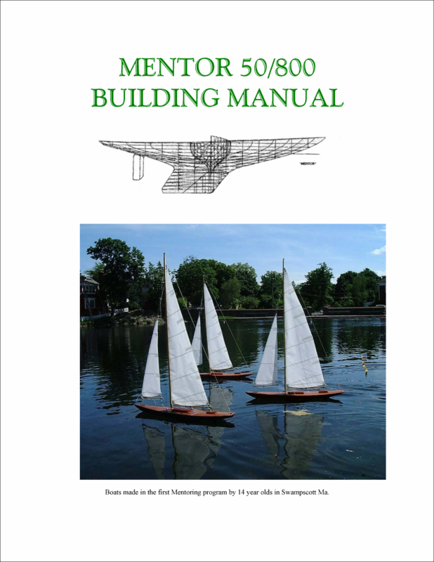
SDale Wenninger’s Mentor 50/800 Building Manual is a comprehensive guide to constructing the Mentor , a radio-controlled Marblehead 50/800 model yacht adapted from H. E. Richardson’s 1930s Madcap design. Created originally as a mentoring project for teenagers working alongside adults, it emphasizes accessible, economical construction, resourcefulness, and the satisfaction of making a capable sailing model from basic materials. The author explains the relationship between the vintage design and contemporary radio control, introduces the tools and supplies needed, and covers essential principles of model-yacht design, scale, buoyancy, balance, and fiberglass construction.
The manual then guides the builder through the complete process: developing hull patterns, making a foam plug and fiberglass mold, laminating the hull, forming the keel and ballast, building and finishing a wooden deck, fabricating the rudder, fittings, spars and sails, and installing the standing rigging and radio-control system. Extensive photographs, full-size patterns and plans, class rules, suppliers, a staged building schedule, and accounts of the original youth mentoring program make it both a practical building manual and a record of an educational model-yachting project. A final section describes later design alternatives and construction updates.
How to use this Manual. Explains how to navigate and print the illustrated manual, use bookmarks and full-size patterns, and access supporting materials.Introduction. Describes the Mentor’s origins as a youth mentoring project, its relationship to Richardson’s Madcap design, and the rationale for fiberglass construction and affordability.Skill level and equipment requirements. Outlines the experience, tools, workspace equipment, and safety awareness required; includes reference weights and balance information for the completed model.Materials list. Itemizes fiberglass and epoxy supplies, woods, metal stock, sails, rigging, fittings, and finishing materials needed for construction.Building Schedule. Provides a staged project schedule for building the mold and yacht, designed around short supervised work sessions and a September-to-May mentoring program.Working with Fiberglass and Resins. Introduces reinforcing cloth and resin choices, epoxy working methods, and safety precautions relevant to making a plug, mold, and hull.It’s a matter of Scale. Discusses how area, volume, ballast, buoyancy, and proportions change when full-size yacht designs are adapted to models.Modeling complex shapes. Explains practical approaches to reproducing and fairing complicated hull and component shapes from plans and patterns. Basic Design Considerations. Reviews the design relationships among hull form, displacement, ballast, sail plan, balance, and sailing behavior.Building Instructions. Begins the illustrated step-by-step instructions for constructing and outfitting the complete Mentor model. Profile and Station Patterns. Shows how to prepare the hull profile and station patterns that establish the shape of the plug. Making the plug and the mold. Details construction, shaping, fairing, and finishing of a male plug and the female fiberglass mold made from it. Laying up the hull. Describes preparing the mold and applying fiberglass reinforcement and resin to produce the hull shell.Cutting out the wood pieces. Prepares the stand, deck beams, decking, bow and stern pieces, deadwood, hatch components, rudder, spars, and control supports.Assembling the stand. Builds the support used to hold the model securely during construction and storage.Gluing up the Deadwood. Assembles the wooden structure joining and shaping the keel and ballast region.Casting the ballast. Covers preparing and pouring the lead ballast casting for the model keel.Installing the deadwood and ballast. Fits and secures the deadwood and ballast assembly to the fiberglass hull.Fairing the keel, installing the deck beams, installing the control floors. Smooths the keel-to-hull transitions and installs supporting structure, including the rudder-post support.Decking. Builds and fairs the deck, glasses its upper and lower surfaces, attaches it to the hull, and finishes the sheer joint.Installing the hatch coamings. Forms and installs the hatch surrounds and explains construction of the hatch covers.Making the rudder/rudder arm. Constructs the rudder and its operating arm for radio-controlled steering.Making the fittings. Fabricates deck and rig fittings such as the jib rack, mast step, chainplates, and gooseneck.Painting and finishing your boat. Describes preparing the hull and surfaces for paint and varnish and applying the finishing coats.Making the spars. Explains shaping and fitting the mast and booms.Making the sails. Gives practical methods for cutting, assembling, and finishing the mainsail and jib.Standing Rigging. Describes mast-supporting shrouds and stays and their attachment and adjustment.Making the Radio Control Mechanism. Explains fabrication of the mechanism and supports used to operate the sails and rudder by radio.Assembling and tuning the boat. Covers installing the radio controls, rudder and sail winch, attaching sails and running rigging, and setting up the yacht for sailing.Patterns and Plans. Collects profile and station templates plus plans for the stand, deadwood, ballast, deck beams, rudder, fittings, controls, waterline guides, spars, and sails.Marblehead 50/800 class rules. Reproduces the class requirements used to assess and configure the completed model.Frequency Chart. Provides a radio-frequency reference for coordinating model-yacht radio-control equipment.Suppliers List & Links to related sites. Lists sources for materials, fittings, radio components, and model-yachting information; contacts reflect the period of publication.Mentoring program. Documents the youth-and-adult boatbuilding project in Swampscott, including a contemporary newspaper account of the boats and participants.Changes and additions. Presents subsequent alternatives and updates, including keel and rudder arrangements and refinements to building and rigging methods.
MENTOR 50/800 BUILDING MANUAL Boats made in the first Mentoring program by 14 year olds in Swampscott Ma. �A SWAMPSCOT BOATWORKS PRODUCTION = – COPYRIGHT 2002 Dale Wenninger Swampscott Boatworks ws Dale Wenninger 11316 Rums Hill Rd. Raleigh, N.C. 27614 919-845-9135 Pdwenn@nc.rr.com �TABLE OF CONTENTS How to use this Manual Programs necessary to use this manual. Introduction 11. Skill level and equipment requirements 13. Materials list 17. Building Schedule 23. Working with Fiberglass and Resins 26. It’s a matter of Scale Volume and Area Ballast and Buoyancy 35. Modeling complex shapes 38. Basic Design Considerations Building Instructions: 43. Profile and Station Patterns 45. Making the plug and the mold 61. Laying up the hull 68. Cutting out the wood pieces: Stand, Deck beams, Decking, Stern and bow pieces, Deadwood, Hatch coaming and Hatch covers, Rudder, Spars, Control mechanism, Control floors 69. Assembling the stand 70. Gluing up the Deadwood 73. Casting the ballast 76. Installing the deadwood and ballast 80. Fairing the keel, installing the deck beams, installing the control floors Installing the rudder post support 86. Decking Fairing and glassing the deck, top and bottom Attaching the deck and fairing the sheer joint �97. Installing the hatch coamings Making the hatch covers 103. Making the rudder/rudder arm 108. Making the fittings Jib rack, Mast step, Chainplates, Gooseneck, Misc. 114. Painting and finishing your boat 117. Making the spars 125. Making the sails 134. Standing Rigging 138. Making the Radio Control Mechanism 146. Assembling and tuning the boat Installing the Radio Controls Rudder, Sail winch Attaching the sails Installing the running rigging 154. Patterns and Plans 156-163. Profiles 164-178. Stations for plug 179-180. Stand 181-182. Deadwood and Ballast 183. Deck beams, Rudder, Bow and Stern pieces 184. Fittings and Rudder arm 185. Radio control mechanism parts 186-187. Waterline guides 188. Sail corner patches 189. Scaleable Low Resistance Bulb 190. Deck beam plan 191. Deck Plan 192. Spar plan 193. Sail plan 194. Radio control mechanism plan 195. Marblehead 50/800 class rules 199. Frequency Chart 200. Suppliers List & Links to related sites 201. Mentoring program 216. Changes and additions on a detailed step-by-step process toward completing a plug (male mold from which a female hull mold is made) in a fast and inexpensive manner using construction �Thank you for purchasing the building manual for the “MENTOR” I designed the “Mentor” as a mentoring project for 14 year olds, but it 1s a great boat for any one wishing to have a boat for themselves, as a project to build with their children or grandchildren, or as a project for any organization geared to youth or adults, such as a Church, Yacht club, Adult education groups. I have spent a great deal of time perfecting this design, but as with any project, it can always be improved and I am doing that on a continuing basis. I would like to update you on new ideas that develop and to hear from you with regard to your thoughts and suggestions as to: How you found the plans, project and boat How I might improve the plans How I might support your efforts This manual is far more comprehensive than is needed to build the “Mentor “ alone. The principals and techniques apply to other models as well. I am in the process of developing manuals for several other boat models, such as the “J” “Rainbow” which is 95 2” long, a “Dark Harbor” which is 52” long and the Schooner “Albatross” which is 50” long. I will be adding to the list as time goes on. You will be able to use this manual and the plans that will be made available to you to build one of these boats, should you wish to do so. By filling out and returning this form, I will be able to tell you of the availability of the plans as they develop and offer them to you at a reduced price. Returning this form also allows you to take a 20% discount on a Mentor hull suitable for building the boat, making a mold, or both. Reducing the cost of the hull from $125.00 to $100.00. Thank you for taking the time to fill this out and return it to us. It is our wish that these boats provide you with as much pleasure in the building and sailing as developing the programs have for us. Dale Wenninger, Swampscott Boatworks 11316 Rums Hill Raleigh, N.C. 27614 Pdwenn@ne.rr.com 919-845-9135 Telephone……………….000cc cece Email………. 0.0… cc cece cece eee ees ( ) for personal use Organization……………..0 ccc cc cece cnc ee eee ees You thoughts and suggestions: �HOW TO USE THIS MANUAL We are offering this manual in two formats: The hard copy provides text with some black and white illustrations bound with the patterns printed out separately and is accompany by over 5 hours of video. This CD format has all of the text and illustrations of the hard copy and has over 650 full color photographs illustrating each step of building the “Mentor”. Because there are a variety of word processing programs in use and because of the limitations of some of them to reproduce images of true size, we used Adobe as the format in which to present this program on the CD. The program is free and must be installed on your computer. The program or information pertaining to it, can be downloaded from http://www.adobe.com/products/acrobat/readstep2.html. or, if you are using Windows, from the file that is located on this CD. It is a very useful program and is widely used. I think that you will find it a program well worth the space on your hard drive if you don’t already have it installed. There are many features to Adobe 5.05 that will allow you to navigate through the pages of the manual with ease. Thumbnails will present you with small pictures of each page that will take you to the page you click on. Bookmarks will also link you to key pages. The Thumbnails tool can be accessed by pressing the F4 key and the Bookmarks tool can be accessed by pressing F5, both can be accessed from “ Window” in the tool bar. The pages and photographs can be reduced in size to 8.33% or enlarged to 1600%. Of course clarity is compromised at such enlarged sizes. I have included all of the full sized patterns that you will need to build this boat. Many of them are too large to be printed full size by your printer as one sheet. To over come this problem, we present the patterns in pieces small enough to be printed out on 8 2°x 11” sheets of paper. You will then be instructed as to how to put them together so that the original shape and size will be preserved. I have included the addresses of many suppliers and links to sites thatI feel you will find helpful and interesting. Their Email addresses will be highlighted in blue. If you have a browser installed and are connected to the Internet, double clicking on them should connect you to their site. I would recommend that you read and view both before you begin your project. You’re on your way to having a lot of fun, enjoy. Dale Wenninger �INTRODUCTION I designed the Mentor to be built as a mentoring project for 14 year olds with an adult, neither of which was expected to have any experience in building model boats. WhenI started this project I discovered that most of the material on building these boats was from the 20’s and 30’s, was incomplete and did not address many of the difficulties of including radio controls. The building techniques used in building the Mentor are contemporary, using modern, easily obtained materials, but preserving the charm and grace of designs from the first half of the last century. There was an intentional effort put forth to teach resourcefulness through a scratch built approach utilizing as few pre-made parts as possible. I sort also to provide exposure to metal and wood working, sail making and working with new materials and techniques such as reinforced plastics. Keeping the requirements simple, but yielding results worthy of high praise. The instructions found in this building manual are complete; including all of the plans and patterns necessary for building the Marblehead 50/800 we call “Mentor”. Also included are: materials lists, supplier’s lists and other resources pertaining to the building and sailing of these boats. The boat below is the boat shown being built in this manual. The “Mentor” is a boat design adapted from a boat designed by H.E Richardson in the mid °30’s that he named “Madcap”. Designed as a free sailer (intended to be sailed �with out radio controls) to the Marblehead 50/800 class. In order to meet the class rules requirements she is 50” long, plus or minus 4” and has no more than 800 sq. in. of total sail area. There are two classes of Vintage Marblehead’s. The Traditional class is for boats that were designed prior to 1945 and those boats clearly designed with the type of boats designed of that era., long overhangs for example. The other class is called High Flyer and contains boats that were designed after 1945 to the late ‘60’s. These boats usually had full waterline length and used balanced rudders. The Mentor was designed for a balanced rudder to allow greater control and maneuverability for the novice sailor. The boat would be sailed against other boats in the High Flyer class when a balanced rudder is used. The boat can also be built with a small skeg and rudder system that would allow it to be sailed as a Traditional class boat. The complete class rules are included under its own section. “T get a kick out of these people who think that we should be making these boats using clamshells for chisels. I think the greatest thing about these old boat builders was their creativity and their resourceful use of the materials of their time. Don’t doubt for a minute that they would have usedfiberglass if they had had it!” Ships carpenter, Essex museum, Essex Ma. This boat was originally designed to be made from wood using the bread and butter lift method or plank on frame. Building the hull is the most difficult and timeconsuming phase of building a boat using traditional methods. The time and talent necessary to build the boat in this way was certainly a consideration when we decided to utilize modern materials, perhaps in the finest of building traditions, and use fiberglass to make the hulls. Equally important in that decision was the fact that making a wooden hull, which would be light, enough to accommodate the added weight of the radio controls would have been doubly difficult. Often, particularly in this sport it seems, most have a favorite way of doing things. The “Best way” to do something is subjective rather than objective. The building techniques described in this manual are “a” way to build the boat. Given all of the criteria that had to be met, I think that it is the best way, but I am always looking for ways for improvement. If you have ideas, they would be welcomed. The plug and mold for this boat should take you about 40 hours to build. There after, building these boats should take approximately 40 to 50 hours. You will be taken �on a detailed step-by-step process toward completing a plug (male mold from which a female hull mold is made) in a fast and inexpensive manner using construction foam, building a mold of fiberglass and plywood from which you can make any number of boats. If you wish to skip the step of building a plug, you may purchase a hull from me, from which you can make a mold, finish the boat, or both. I wanted this manual to be as comprehensive and useful as I could make it. It covers a great deal more than how to just make the Mentor. The Mentor requires only a one-piece mold, for example, but in the event that you wanted to build a model that required a two-piece mold (you will be told in what cases that might apply) you are shown how. There are many examples of how this manual extends beyond the building of only this model. You will be shown how to; Utilize plans for real boats and apply them to a model you wish to make, and how to scale ballast shapes and weights as well as sail dimensions and balancing your adapted design. You will be shown how to make both male and female molds, lay up hulls using fiberglass, cut and shape all of the wooden pieces for deck beams, decking, combings and spars, cast the ballast, make all of the fittings (with the exception of a deck block and thru hull fittings) from brass stock, fabricate the sails and make and install the radio controls. In order for this boat to be utilized as a mentoring project, its cost had to be very affordable. The costs for this boat which would fall with in the $1500.00 to $2000.00 range on the retail market is designed to come in at under $175.00-including the radio controls! There is an economy of scale however. The materials you will need to purchase are in several cases, larger in quantity than what would be needed for a single boat. An example is that nearly three sets of sails can be made from a single yard of sailcloth. If you make only one set, the cost of the single set would be the same as three. There is something about telescopes, electric trains and model sailboats that brings a smile to our faces and compels us to revisit our youth. This boat certainly does have that affect on us. It’s grace, speed and agility under sail is a pure joy to watch and never fails to draw a host of admiring and smiling faces. Its 50” size will make an impressive decorative addition to your home as well. You are on your way to hours and perhaps generations of enjoyment. I have found it to be an ideal project for many situations. Whether it is for a youth group, winter project for a yacht club involving youth �or adults, or a project for a parent or grandparent to build and use with a child or grand child. It goes without saying that it is an excellent and rewarding project for anyone to build and sail, just for him or herself. The one thing that the boat is not is “just a toy boat”. Though it can be sailed by a child, it is a sophisticated and competitive model that will be in good standing with any boat in its class. If you have any questions or comments, I would be delighted to hear from you. I am always looking for ways to improve my designs so your suggestions will be most welcome. Enjoy. Dale Wenninger 73 Fuller Ave. Swampscott, Ma. 01907 781-598-6957 Pdwenn@attbi.com �SKILL LEVEL AND EQUIPMENT LIST I have found that nearly anyone with an interest and desire to build these boats and the ability to follow instructions carefully can do this project. The key is that you proceed thoughtfully and pay particular attention to details. In giving the instructions, I assume that you do not have experience in such projects and that you require a full and complete explanation as to how to proceed. As with any procedure, there is a learning curve. Laying up the hulls may require that you make one to get the “feel” of the process if you have never worked with fiberglass before. Like the New Yankee workshop, good tools make a project easier, but with a little more effort, more simple tools will do. While a band saw is not necessary, a hand held saber saw will suffice, a band saw makes the cutting out of many of the pieces a lot easier. A small drill press and small band saw suitable for this project can usually be had for around a $100.00 each if you want to make the investment. You will need the use of a table saw for an hour or two to strip out the planking and the striping of some of the stock for the spars and coamings. You will need to know how to use this equipment safely, or have someone do these tasks for you. Among the other tools that you will require are as follows: Small table drill press or 3/8 electric drill and stand Palm sander Hot knife for cutting out sail pieces (900 F)-Found at craft shops Soldering iron or torch for soldering some of the fittings Dremel tool, (again, not completely necessary, but very handy) Glue gun Hacksaw Course rasp 10” Metal file Screwdrivers Needle nose pliers Regular pliers 4/40 tap with handle Razor saw Putty knives, | 2” and 5” Scissors Pocket level 1” Wood chisel (round off the corners for scraping the underside of the deck) Ys” Wood chisel Utility knife Nail set (punch) Hammer Square 4” vice for bending the brass fittings 2 16” Bar clamps 12 spring clamps Measuring tape Ruler �Propane torch for melting lead Ladle to melt lead in BOAT WEIGHTS Bare hull with sheer strips……………..0…..c ccc ee eee 2 Ib. 4 0z. Deadwood w/o ballast………… 00… c ccc eee eee ees Ballast…… 7 OZ. 0.0000. c ccc ccc cece cece eee een e teen eben teens 8 Ibs. 12 oz. Boat with deck, ballast, deadwood……………… 13 Ibs Hatch covers…… Main 4 oz. Rudder 1 oz. ……………… 5 OZ. Electronics: Rudder S€rv0………… ccc ccc cece cece cece ees Drum Winch…………..0 ccc ccc cece cece nee ee ees JoNSSS 110 | 0) Dn Battery pack w/batteries………………….05. 00) | a Sail rig-spars & Sails……… 000k ccc cece cece eee eee 1lb. 1 oz 5 0Z 6-1/2 oz 4 oz. 10-1/20z. loz. Total displacement of boat, fully rigged with batteries……………… 15 Ibs. 1 oz. Balance point of boat with out sail rig but with batteries forward – 2 *4” aft of front edge of keel. Balance point of boat fully rigged with sail rig and with batteries forward – 2 1/8” aft of front edge of keel. Boat should float with the bow 1-1/4” higher above the waterline than the stern. Painted waterline 9 ‘4” above the bottom of the keel. Actual waterline 9” above the bottom of the keel. �MATERIALS LIST Supplies and Raw materials: For plug, mold and hull Durham water putty-Plug Wallboard seam tape-Plug 12 box nails-Strong back All-purpose glue sticks Pink construction foam (1) 24”’x8’x2” —foaming plug (24) 1 ‘4” disposable chip brushes 4 yards 38” 2 oz. fiberglass clothe 8 yards 38” 6 oz. fiberglass cloth (E glass) 1 yard 240z woven rovings 1 (B) size West System epoxy with fast hardener (305) —with pumps 1 (A) size Special with-with pump (307) 1 tube black pigment 1 tube white pigment 1 pint PVA mold release 1 small can mold release wax High density filler West system 404 1 small Tight bond wood glue 80, 120, 220 grit sandpaper 1 2”x18” coarse sanding belt- you will make a fairing board with this. 24 10 oz. plastic cups 6 paper plates 24 pair latex gloves Masking tape-2” and 1” Paint and varnish Safety Items. Safety glasses Dust mask Heavy work gloves-for when you melt the lead Wood pieces Strongback-Pine (2)%x1’%x 53” (1) %x3’%x 53” (1) %x 3 %x 53” cut into spacers with 1/8″ grove running the length Plug ‘% (4×4) sheet of luan plywood for stations, Keel piece and mold separations Ends of stand can also be gotten from this sheet as well as control floors Mold sheer strips (4) ‘2x ‘4x 54” spruce or mahogany 13 �Hull sheer strips (2) 2x 3/8 x 50” spruce Stern piece Ys x 1 x 4” spruce or pine Stand 16% x 8 4” pine (2) 8 ‘4x 11 luan plywood Deadwood & ballast plug ¥4x 1 ‘4x 9 linear feet of spruce or pine Deck beams Yx1l’x24” %4×1%x 24” center beam Decking 3/16 x 5/16 spruce 80 linear feet 3/16 x 5/16 mahogany 20 linear feet 3/8 x 1 2x 10” mahogany bow and stern pcs Y2X 2x 6 1/2 “ mahogany rudder Hatch covers and coamings 1/8 x 1 42x 6’ mahogany Hatch coamings and sides 3/8 x 1 x x 5’ mahogany Hatch tops Rudder control floor 1-5/8 x 3- 5/8 x %” pine Spars Ya X %x 65” spruce Mast Y2 X 3/8 x 3” spruce Winch assembly Ys x 1 x 24” hard wood, mahogany for winch arms Y2X 1-‘4 x 4-‘4 spruce winch mount Total amounts Luan plywood (1) 4’x4’ sheet Mahogany (1) %x4x 60” Pine ¥,x 10 x 24” �Spruce (clear 2×4) You may have to buy a couple to get all of the clear stock that you need. (1) We use a single clear straight-grained 2×4. Unfortunately clear 2×4 are difficult to find. The tight grain and toughness of spruce makes a much superior wood to work with than pine for the spars and the decking. It 1s worth the trouble to look through the stack for good stock and even purchase more than 2×4’s than you might need in order to get enough clear stock. It is not necessary, but we found that accent pieces for the bow and stern, hatch covers and coamings, sheer trim, and rudder made of a different kind of wood makes a nice contrast. A harder wood such as mahogany makes a nice contrast and gives a more durable wood to endure impacts, should they occur. It is also best for the support strips along the molds sheer line. Lead for ballast: Twelve pounds of old tire weights from you local service station. It should be noted here with a little humor that some time some 75 years ago someone made the comment that tire weights should not be used because the material was somewhat lighter than scrap lead. I challenged that assertion. Lead weighs 700 Ib. Per cubic foot or 6-’2 oz. per cubic inch., so does tire weights. Of course the weights have to be melted and the steel removed. NOTE: Lead melts at about 500 degrees, Adults should do this and do this outside out of the fumes and on a dirt surface should any of the lead spill. Brass stock: 3/16 1.d. tubing-12” for rudder tube and spar ends 3/16” rod for rudder post 6” 4”’x4” 32 gauge for jib rack, chain plates, mast step, and tangs 21/32”1.d.x2” for mast end (1) ‘4”x 20 insert for mast jack (1) ‘A” x 20 x3” galv. bolt for mast jack (1) 1/8”°x12” solid brass rod for rudder connecting rod (1) 1/8”x3” tube for shroud sleeves (1) 7/16 brass tube (1) 9/16 brass tube Sails: (1) yard 50” wide 2 oz. Dacron for main and jib. This can be difficult to find, especially in the quantities that would be necessary for only one of two boats. Regular 4 oz. Dacron is too heavy. 1.5 Ripstop Nylon will work very well as well. It cost about $10.00 per yard and is 54” wide. 2” Dacron repair tape (6) ss eyelets Standing rigging: �4’ 1/16″ x7 ss cable divided into two 3-strand cables or preferably 8’ 1/32 ss cable Running rigging, Sheet and control line 100Ib braided fishing line (2) 80 Ib fishing swivels (3) ss split rings (1) barrel swivel (4) closed clips Bowsers, (1) 10” Duct tie (1) Cheek block Pekabe Fit-P512 (1) ss hook Pekabe Fit-P408 (2) Thru hull fittings Pekabe Fit-P470 $8.45 25 5.45 each (nylon through hull fittings can be used as a substitute) Peekabe fittings found at Worth Marine. Paint A good grade topside paint, each boat requires about 3 oz. A good grade exterior varnish with UV protection for spars and deck. It’s expensive, but Epifanes paint and varnish is the best and I think that it is well worth the money, given the ease with which it can be applied and the quality of the finish you will receive. Struggling with several coats of a cheaper varnish can make the extra cost a real bargain. Misc. Latex gloves (5) Pair. 80 grit, 100 grit, 220 grit, sand paper. (1) 1/4×20 galv. Bolt, nut and washer for deadwood. All purpose glue sticks, 1” and 2” masking tape, 1” foam brushes, Paper plates, 10 oz plastic cups, 2” chip brushes, 16 �Building Schedule As I had indicated in the introduction, this boat and program was originally designed as a mentoring program. The following building schedule is laid out so that a program could begin in September and end in May. The schedule for building the boats during that period does not include the time that it would take to make the mold. The program intended that the adults would do that before the program started and rough out the parts the kids would need in the interim between the meetings. I have included a copy of the schedule here so that you can get an idea of the number of steps and time required to build a boat. Each step is designed to be accomplished in about two hours. BUILDING THE MOLD 1. GETTING STARTED Print out the station patterns, coping the patterns to plywood, cutting out patterns, and making a strong back and spacers. 2. BUILDING THE PLUG Assembling the stations, filling the framework with foam, 1“. coat of water putty. 3. FAIRING THE PLUG Fairing the plug, additional coats of water putty, checking dimensions. �4. GLASSING THE PLUG (less than a hour) Fairing the plug, glassing with 2 oz. cloth. 5. FAIRING THE PLUG 6.FINAL FAIRING OF THE PLUG 7. MAKING THE MOLD 8. LAYING UP THE MOLD Glassing the plug, cutting out the plywood support structure and sheer strips . x ® i ae 9. REMOVING MOLD FROM PLUG Removing mold from plug, adding sheer strips, support structure. 18 �10. FINNISHING OF THE MOLD SURFACE Checking the interior surface of the mold, final finishing and waxing BUILDING THE BOAT 1. LAYING UP THE HULL Hull lay-up, stripping out decking, sheer strips, cutting deck beams, bow and stern pieces, spar stock, deadwood pieces, cutting and assembling the stand. Gluing up the deadwood. 2. REMOVING THE HULL Removing the hull from the mold, installing the sheer strips and ribs, installing temporary spreaders, cutting and shaping the deadwood. Casting the ballast. Note: The kids would become involved at this point . 3. INSTALLING THE DEADWOOD AND BALLAST Installing the deadwood and ballast, finish shaping the spars and rudder. 19 �4, FAIR HULL/DEADWOOD/BALLAST Fair and fill hull, deadwood, ballast joints, install deck beams, make mast jack and base. 5. PLANK DECK Install bow and stern pieces, king plank, plank deck. 6. FAIR DECK/GLASSING DECK Finish fairing and sanding deck, glass with 20z. cloth 7. FAIRING/GLASSING UNDERSIDE OF DECK Removing deck, fairing underside and glassing underside, installing rudder tube 8. ATTACHING THE DECK Installing the control floors, attaching the deck to the hull, making the fittings 20 �9. FILLING/FAIRING SHEER JOINT Installing the hatch coamings, filling and fairing the sheer joint, finishing the spars. 10. MAKING THE HATCH COVERS Fair the sheer joint and final deadwood/hull/ballast joints, prepare the entire hull for finishing, and make the hatch covers. 11. FINISHING THE HULL Drawing on the waterline, first coat of paint, make winch controls 12. FINISHING HULL/MAKING SAILS Second coat of paint, make sails �13. INSTALL CONTOLS/FINISH DECKS Install the winch and rudder controls, varnish decks and spars (at least 3 coats of varnish) 14. INSTALL FITTINGS/STANDING RIGGING Install all of the deck fittings, make shrouds, assemble boat with running rigging, attach main and jib sheets. 15. ATTACH SAILS/RUNNING RIGGING Attach the sails and running rigging, modify transmitter, initial adjustments of controls. 16. LAUNCH THE BOAT! Launch the boat, take lots of pictures, graciously and modestly accept the complements, enjoy the moment. There will of course be steps which will take a little more and somea little less time, all in all the boat will take about 40 hours to build and a life time to enjoy. 22 �Working with Fiberglass and Resins There are an almost limitless variety of resins with different qualities and as well as safety concerns. Polyester resins are the least expensive, about $20.00 per gal. vinylester is a little more expensive, about $29.00 per gal, but is a little stronger. Epoxy has even more variety with regard to hardners, some will work at lower temperatures than others, some offer a clear coat, and others change color, as they are older and exposed to air, giving your coat a shade of color. There are epoxies, which stay relatively flexible, while others are very hard and brittle. Epoxy can run nearly 3 times what polyester resins cost. Epoxy is significantly stronger than polyester and vinylester and epoxy works well as an adhesive, where the other two do not. Both polyester, vinylester and epoxy are thermosetting resins, that is, they generate heat as they cure and they cannot be melted or liquefied again by the application of heat as thermoplastic resins can. Epoxy will adhere to polyester; polyester will not adhere to epoxy. Epoxy will act as a better moisture barrier than polyester than polyester, making epoxy suitable for strip built boats where polyester would not be. There are many differences between cloth reinforcing material as well. Fiberglass reinforcing materials are made from glass filaments, which have the same ingredients as ordinary window glass. These filaments made in different ways to have different qualities of strength, abrasion resistance, flexibility, chemical stability etc. A letter code such as “E”, A, or “S” designates different types of glass. “E” and “S” are most commonly used, “S” being stronger than “E” but more expensive and more difficult to “wet out” saturate, they should really be used with a vacuum bag. These glass filaments are available in a variety of materials, rovings, yarns, cloths, mats and woven rovings. When these materials are made, the strands of filaments must be coated with a sizing material. This sizing material allows the monofilaments to bind together which makes up a strand, to lubricate the filament so that they won’t abrade or break each other and to increase the surface contact between fibers and resin, that is to increase the quality of the fibers to soak up resin rapidly, called wettability. Sizing materials are incompatible with resins and must be cleaned, or finished, so the resin will saturate and bond to the fiberglass. Chrome and silane are two finishes which are commonly used for marine use and give the fiberglass materials their “white translucent” appearance. Some materials do not have this appearance, having a dirty or greasy appearance, such materials have not been finished and you shouldn’t buy them, no matter how cheap they are. Of course, in addition to fiberglass materials, there are other materials, such as Graphite, Kevlar, Polyester, Nylon, and Dynel, to list a few, each with their own special qualities. I say all of this and leave the subject, not to confuse you, but to say that the comprehensive understanding of these materials is way beyond the scope of this manual. Should you want to explore the subject further, I would suggest: “Fiberglass Boat building for Amateurs” by Ken Hankinson published by Glen-L Marine designs 9152 Rosecrans, Belolflower, CA 90706. I have used many different epoxies and reinforcing materials in building kayaks, both strip built and fiberglass, as well as full sized sailboats and Wherries. For the 23 �purposes of building this r/c sailboat model, I choose West System with a fast hardener for the lay-up and the special hardner for the deck surface. I chose epoxy over polyester because of the construction techniques I developed for the boat required that I use a stronger resin, which would have higher water barrier qualities and would be a superior adhesive, as well as giving a clear finish. The deck, for example, is of a “stress skin” construction. That is to say the core material, the planking, does not provide much structural strength beyond separating the two layers of cloth, which are in tension with each other. The result is a super strong laminate for its weight allowing for the elimination of a mast support under the mast, which is stepped on the deck. I chose the materials I suggest considering cost, and physical characteristics, which I thought would be most suitable for the project. They have proven to serve the purpose well, however should you want to go further with one aspect or another than I would encourage you to seek information beyond what I can offer you here. An example might be if you want to use the principals outlined in this manual to make a super hi tech model from Graphite fiber. I am going to include in this section, some safety issues in using these materials. I strongly urge you to acquire the user manuals provided by the manufactures of these materials and that you follow their guidelines. That, of course, would apply to the use of tools as well. Nothing that I say in this manual should be taken as to over ride the guidelines of these manufacturers. I cannot possibly foresee all of the conditions that you will be working with. Please, take the time to educate yourself and be safe. West System support can be obtained from: Gougeon Brothers, Inc. P.O. Box 908 Bay City, MI 48707-0909 517-684-1374 www.westsystem.com The following safety precautions has been taken from West Systems User Manual: EPOXY SAFETY Epoxies are safe when handled properly. To use WEST SYSTEM epoxies safely, you must understand their hazards and take precautions to avoid them. HAZARDS The primary hazard associated with epoxy involves skin contact. West System resins may cause moderate skin irritation. West System hardners are corrosive and may cause severe skin irritation. Resins and hardeners are also sensitizes and may cause an allergic reaction similar to poison ivy. Susceptibility and the severity of a reaction vary with the individual. Although most people are not sensitive to West System resins and hardners, the risk of becoming sensitized increases with repeated contact. For those who become sensitized, the severity of the reaction may increase with each contact. These hazards also apply to the sanding dust from epoxy that has not fully cured. These hazards decrease as resin/hardener mixtures reach full cure. Refer to product labels or Material Safety Data Sheets for specific product warnings and safety information. PRECAUTIONS 24 �1. Avoid contact with resin, hardners, mixed epoxy and sanding dust from epoxy that is not fully cured. Wear protective gloves and clothing whenever you handle West System epoxies. Barrier skin creams provide additional protection. If you do get resin, hardener or mixed epoxy on your skin, remove it as soon as possible. Resin is not water soluble-use a waterless skin cleanser to remove resin or mixed epoxy from your skin. Hardener is water soluble-wash with soap and warm water to remove hardener or sanding dust from your skin. Always wash thoroughly with soap and warm water after using epoxy. Never use solvents to remove epoxy from your skin. Stop using the product if you develop a reaction. Resume work only after the symptoms disappear, usually after several days. When you resume work, improve your safety precautions to prevent exposure to epoxy, its vapors and sanding dust. If problems persist, discontinue use and consult a physician. 2. Protect your eyes from contact with resin, hardeners, mixed epoxy and sanding dust by wearing appropriate eye protection. If contact occurs, immediately flush the eyes with water under low pressure for 15 minutes. If discomfort persists, seek medical attention. 3. Avoid breathing concentrated vapors and sanding dust. West System epoxies have low VOC content, but vapors can build up in unvented spaces. Provide ample ventilation when working with epoxy in confined spaces, such as boat interiors. When adequate ventilation is not possible, wear a NIOSH (National Institute for Occupational Safety and Health) approved respirator with an organic vapor cartridge. Provide ventilation and wear a dust mask when sanding epoxy, especially partially cured epoxy. Breathing partially cured epoxy dust increases your risk of sensitization. Although epoxy cures quickly to a sandable solid, it may take over two weeks at room temperature, or elevated temperature post-curing, to cure completely. 4. Avoid ingestion. Wash thoroughly after handling epoxy, especially before eating. If epoxy is swallowed, drink large quantities of water—DO NOT induce vomiting. Because hardners are corrosive, they can cause additional harm if vomited. Call a physician immediately. Refer to First Aid procedures on the Material Safety Data Sheet. 5. KEEP RESINS, HARDENERS, FILLERS AND SOLVENTS OUT OF THE REACH OF CHILDREN. Again, the User Manual is free, I urge you to read it thoroughly. In addition to safety issues, it will find that it gives you a very good basis of understanding as to how to use these materials. 25 �IT’S A MATTER OF SCALE “T have a model that is 25” long, weighs 1 2 lbs. and has 180 sq. inches of sail. I want to double the length so that it will be 50 inches long with the same proportions. My model will end up being 50” long, weigh 3 Ibs. and have 360 sq. inches of sail, Right?— WRONG! The logic that every dimension will double because the length doubles does not hold up when dealing with area and volume. If you double the dimension of a 2” sq. that has 4 sq. inches in its area, you end up with, not 8 sq. inches, but 16. 16 sq. inches – 26 �If you double the dimension of a 2” cube that has 8 cu. Inches in it, you don’t end up with 16 cu. Inches, you will have 64 cu. Inches. 64 cubic Inches Total The original model is 2 the length of the model you wish to build. The sail area of the original is 180 sq. inches. 180×2 (because the new is twice as big)=360×2=720 sq. inches. The sail area of the new model will be 720 sq. inches in area. If you were going to make it 4 times longer, than the original would be 4 the size so you would use a factor of 4 instead of 2. 180×4=720×4=2880. The new sail area for your 100” long model would be 2880 sq inches. The weight of your boat model is a factor of volume. The example of a cube would come into play. The original boat model weighs 1-’2 lbs. If you wanted to double its length you would calculate the weight of the new 50” model like this: 1.5 Ibs.x2=3×2=6×2=12. Your new model would weigh 12 Ibs. If you were going to make it 100” long or 4 times bigger, 1t would be calculated like this: 1.5 lbs.x4=6×4=24×4=96. Your new model would weigh 96 Ibs. 27 �What if you had the plans for a real boat and wanted to make a model of it. How would you calculate the size and weight? If we use the Dark Harbor for an example, we have a 26’long boat with 310 sq ft. of sail and 1500 Ibs. of ballast. Here is how we calculate the sail area and ballast for a model of the Dark Harbor that is 52” long: 52” is 1/6″ the size of the real boat. 52”x6=312” or 26 feet. The sail area of 310 sq. ft is divided by 6 and then 6 again. 310 divided by 6=51.666 divided by 6= 8.611 sq. ft. times 144 (sq inches in a sq. ft) = 1239.98 sq. inches of sail. The 52” model would have 1240 sq. inches of sail. A cubic foot of lead weighs 682 Ibs. 1500 divided by 682=2.199 cubic feet 1500Ibs divided by 6 = 250 divided by 6 = 41.667 divided by 6 = 6.95 Ibs 682 Ibs (cu. Ft of lead) x 16 oz. = 10,912 divided by 1728 (# of cu. Inches to a cu. Ft.)=6.31 oz. A cu. Inch of lead weighs 6.31 oz. 6.95 lbs x 16 oz.s = 111.2 oz. divided by 6.31 (# of oz. in asq. inch) =17.62 cu. Inches. The ballast for the new model at 1/6″ scale will be 17.62 cu. Inches of lead weighing 6.95 Ibs. Now that we know this, how do we make a mold to scale that will equal what we need? There is a simple way to figure out what the weight and the volume of a shape will be. 28 �I use high-density yellow construction installation foam. It is inexpensive and very easy to work with. 1. Cut and shape the ballast that you will need according to the plans that you have scaled to your needs. eT ) 14918 Yas ABS EAR a8 29 �2. Place enough water in a glass container so that your foam ballast can be completely submerged in it. I used a glass-baking pan. Make sure that the surface you place your container on is level. Mark the water level on the side of the container. 3. 4. Totally submerge your foam ballast in the water and mark the new water level. Remove the foam ballast and add enough water to bring the water to the higher watermark. 5. Place a container that is large enough to hold the volume of water that you added on a scale and bring the scale setting back to “0” so that the container is not being weighed. 6. Remove enough water from the container that you submerged your ballast in so that the original water line is meet. Put the water that you remove into the container on the scale. 7. You will be able to calculate the weight and volume of the ballast if it were made of lead from the weight of the water you removed. If you removed 10 oz. of water, for example, your foam ballast would weigh 6.875 Ibs if it were made of lead. 10 oz. x 11 (the specific gravity for lead) = 110 oz. divided by 16 = 6.875 Ibs. Fresh water weighs 62 lbs or 992 oz. per cu ft. or .574 oz. per cu. Inch (992 divided by 1728-# of cu. Inches in a cu. Ft) 10 oz. divided by .574=17.42 cu. Inches 6.875 Ibs divided by 16 = 110 oz. divided by 6.31 = 17.43 cu inches. Finding the center of gravity of your ballast is also very important. Once you attach your ballast to your hull, you will want it to float properly. If the center of gravity is not right your boat will float bow up or down or may lest to one side or the other. Figuring this out is especially important if you have changed the shape of the ballast for one reason or another. This may happen if you need to change the shape in order to bolt the ballast to the deadwood more easily because of the model characteristics. You may also wish to lower the center of gravity in order to make the boat more stable while maintaining the original water line. I was presented with this problem while designing a ballast plate for a “J” boat model. I wanted to bolt a removable ballast plate to a “J” hull and I also wanted the weight of the plate to be as low as possible while maintaining the original profile. The answer was to make a slight bulge along the bottom edge of the plate while maintaining the same balance point fore and aft. I also designed a removable fin and bulb keel for a “J°. Making these shapes while keeping them inside the design parameters is easier than it might seem. See the next section “Making complex shapes” It is likely that, while the plans may show the balance point of the boat, it will not show the balance point of its ballast. Determine the balance point of the original ballast design by making a model of it out of foam and rolling it on a dowel that is at a 90 degree angle to the waterline of the boat if the ballast was attached to it. Mark the balance point on your foam ballast and transfer that point onto your plans. Roll your new foam ballast on a dowel in the same manner. Note where this point would be along the length of the original plans. You would then attach your keel so that 30 �the balance point of both ballast and boat would be in the same spot along the length of the waterline, but not necessarily the same depth. How to calculate floatation volume I have been asked how to calculate floatation volume. “T don’t want my model to sink if it’s been holed. How much foam do I need to give it positive flotation? My boat weighs 15 lbs, fresh water weighs 62 2 lbs per cubic foot, and the foam weighs 2 Ibs. Given a % lb safety factor, a quarter of a cu. Ft, right?” Well, not precisely. Specific gravity means the ratio of mass of an object to that of an equal volume of water. For example, a cubic foot of solid fiberglass weighs about 115 lbs., while a cubic foot of salt water weighs about 64 Ibs. Thus, 115 Ibs. divided by 64 = 1.8 Specific Gravity. Fiberglass is 1.8 times heavier than salt water. Any object with a specific gravity over 1.0 will not float and it has negative buoyancy. Any object with a specific gravity less than 1.0 will float, An object with 1.0 has neutral buoyancy. The first step in solving our problem of finding out how much foam is needed is to figure out the specific gravity of the materials making up the weight of our boat. W= Weight in Ibs of an object in air S= Specific gravity of an object PB= Portion of weight in lbs. With positive buoyancy. NB=Portion of weight in Ibs. with negative buoyancy. F = Flotation value of foam in Ibs per cu. Ft. Our boat(for example) has a total weight or displacement of 14 Ibs. 14 oz. The total weight is made up of: Specific Gravity (S) Fiberglass 1lb. 402z. 1.6 Wood 2 Ibs 10 0z.(spruce) 42 Metal 6 Oz. 7.8 Electronics Ilb. loz 2.6 Lead 9 lbs. 9 oz. ll. W= 14 lbs. 14 oz. Negative buoyancy materials (Weight would be negative numbers because they have a negative buoyancy) Fiberglass: -1 Ib 4 oz. (-20 0z.) divided by 1.6 = -12.5 +20 (add back the original weight) =7.50z NB Metal: -6 oz. divided by 7.8 = -.77 +6 Electronics: 3] = 5.33 0z.NB �-1 Ib. 1 oz (-17 0z) divided by 2.6= -6.5 +17 = 10.5 0z. NB Lead: 9 Ibs. 7 oz. (-153 02z) divided by 11= -13.9 +153 = 139.1 0z. NB (W) 196 oz. 162.40z NB Positive buoyancy materials Wood (spruce) 2 Ib 10 oz. (+42 02.) divided by .42 = 100 —42 = 58 0z PB (W) 42 58 oz. PB 162.4(neg. buoyancy)— 58 (pos. buoyancy) =104.4 oz NB Foam flotation value (Fresh water): 62.5-2 (weight of the foam) = 60.5 Ibs per cu. Ft. or 60.5x 16(0z.)=968 oz. divided by 1728 (# of cu in. in acu. Ft.)=.560z per cu in. (F) 104.4 divided by .56=186.43 cu in of foam needed to give our boat positive floatation, not 432 cu in. If we use a standard 33% safety factor, 248 sq in of foam would be needed. A 1-3/8”x 1-3/8” x 48” (1.375×1.375×1.375=2.6×48=124.8×2=249.6sq in.) strip running along each sheer just under the deck would give us the 248 sq in. we need It will add 4.6 oz to the weight of our boat. 2 Ibs. (32 oz.) divided by 1728 = .0185 oz. Per cu. in. 249.6x.0185=4.60z. NOTE: You will want to use closed cell foam, you don’t want water to be absorbed by the foam. I would not recommend that you use a foam that expands inside your boat. The expansion of these foams exert a great deal of pressure and is apt to distort your hull badly. I experimented with filling a hull with foam while it was still in the mold. I wanted to create a very rigid hull for a plug from which to make other molds. It was so badly distorted that I threw it out. It would be mush wiser, I think to figure out the volume of foam you need and then cut it into shapes that worked for you in your particular application. Either that, or mix the foam in very small batches, a teaspoon at a time, and make sure that the foam has plenty of room to expand with out exerting pressure on your hull. Low Resistance Bulb I have included the plans for a low resistance ballast bulb design . If you print copy the plan so that the square is one inch exactly, the bulb will weigh 6.875 Ibs if you cast it in lead. If you increase the size of the square to two inches, the bulb will weight 55 pounds. 6.875×2=13.75 x 2 =27.5 x 2 =55. You can there by determine the size dimensions of the bulb you will need by adjusting the size of the square. Take the plan to your local copy center and have it enlarged or reduced by the amount that will give you the ballast weight that you need. 32 �Example: You need a bulb that will weigh 9.5 pounds. How big does the square have to be? 9.5 divided by 6.875=1.38 .38 divided by 3 = .1266 6.875 x 1.12 = 7.7 x 1.12 = 8.624 x 1.12 = 9.65 Not perfect, but it will get you into the ballpark. Make your square or plan 12% larger and you should be close. Cut your profile and top view from foam, shape the foam according to the shadows making up the cross sections, and figure out the volume according to the directions we just covered by submersing it in water and figuring out the weight of the water it displaced and multiplying by 11. Once you are satisfied with your shape and weight, (you can check it by finding the volume in water and adjusting the shape accordingly) cut the foam in half, epoxy it so that it will be durable and cast each side separately as shown in “How to cast your ballast”. Make up an epoxy paste and the two half’s together. How about if you need a bulb that is only 4 Ibs, what then? Albs divided by 6.875 = .58 58 divided by 3 = .19 6.875 Ibs. divided by 1.19=5.777 divided by 1.19=4.85488 divided by 1.19= 4.080 Ibs. If you made the square 81% or about 13/16″ of an inch sq. you would have a bulb that would weigh about 4 Ibs The pictures below were taken of a real ocean racer in Newport RI. They show a real boat application with a similar design. 33 ��MODELING COMPLEX SHAPES Drawing complex shapes that provide a three dimensional representation can be very difficult. Often the easiest way to do this is simply make a model of what you want to draw or recreate. —P 2 te SARTO Be === be Pd br by tI} “— 7 qs The example I use is for ballast plates that I developed for a “J” boat model. I wanted the ballast to be removable, bolted on to the hull from the outside. I was presented with a number of problems that I needed to solve. The shape and position of the ballast would be different than what was indicated on the plans. As the keel tapers, I ——, would have to find the balance point of the ballast and the volume (new dimensions of the ballast). I would have to locate the ballast on the hull so that the weight would be properly distributed along the length of the boat so that the boat would maintain its original water line. I also wanted the weight to be as low as possible while maintaining the original profile. �I knew that the ballast would be about | 2” thick, I started with a piece of foam 2” thick cut to the profile that I needed. I also knew that the volume would be one half of the amount I needed, as I would put two of the plates back to back to get my total weight. To some degree, this would be trial and error. I would have some lee way by adjusting the thickness of the ballast on the inside whenI cast it. You may know the balance point of the boat ballast from the plans. How ever if that point is not indicated on the plans you are using, or you wish to change the shape of the ballast, create the ballast from foam according to the original plans you wish to model. (Using foam or lead doesn’t affect the balance point, it will be in the same spot) Mark that point on your foam ballast and then transfer that point to your plans and your hull. No matter what shape your new ballast will take, the new ballast’s balance point and the balance point of the original ballast should be placed the same in relationship to the hull. Transferring the basic shape to the plans will give you an idea as to the keel thickness and shape of the ballast on the top edge. So, in summary, I knew the profile, there by the length. I knew the thickness and shape of the top edge. I knew where I would have to locate the balance point along the length of the profile. I also knew that I wanted as much volume as low as possible and I knew the shape and the width of the back edge. Armed with that information, I began shaping the sides of the foam. I first brought the top and back edge to where they must be to be fair to the hull once the ballast was installed. The next step would be to form the bulge on the bottom edge. I constantly checked the balance point of the foam plate as I was sculpturing it by rolling it on a dowel. Through this process, I gradually created a very complex shape, which fit my needs. I then submerged the foam plate in water according to the method described in “It’s a matter of scale”. Calculating the sq. inches of the flat side of the plate would be fairly simple and I could calculate and adjust the weight (volume) of the plate by varying the thickness along that flat side. A cubic inch of lead weighs 6.25 oz. per sq inch of lead 1/8” would weigh 1.5625 oz. for example. Ok, that wasn’t too bad, but now I have to recreate my shape in a mirror image for the other side so that the two plates will be symmetrical both in shape and weight. Doing one side is easy compared to duplicating it for the other. I glued the foam plate I had shaped to a rectangular piece of plywood so that I had about a 2” extra around the top and sides and a minimum of 2” on the bottom. I then 36 �orientated a line relating to a station position on the plan as a reference point. Then, in equal lines about an inch apart (this may vary with the distance between stations) I drew straight vertical lines along the length of the plate. I then took a thin (as close to the thickness of poster cardboard as you can get) straight back saw and cut through the foam to the plywood along each of those lines. I made sure that the cut was completely through the foam, but not into the plywood. I then cut rectangular pieces of cardboard for each line that were the same length as the ply wood was wide and ’2” wider than the foam plate was at it’s thickest point. Starting at one end, I placed a piece of the cardboard into the cut, making sure that it was flat against the plywood and that the top edge of the cardboard was even with the top edge of the plywood. I then drew the shape of the foam plate at that point by drawing a line on the cardboard that followed the edge of the foam plate. I did the same for each line or station. The next step was to cut a second piece of foam with the same profile and of a greater over all thickness of the original. I glued this second piece of foam to a second piece of plywood of the same shape and size as the first. Using the station lines of the first piece of plywood, I transferred the lines to the second piece and cut the lines through the second piece of foam down to the plywood. Remember that you are making a mirror image of the first plate! That means that if the front of the first plate faces left, the front of the second plate wouldface right. Make sure that the station lines that you transfer relate to the same position for both plates. I then cut the silhouette of the stations from the cardboard pieces that I drew. Using the station (the male portion) rather than the shadow (female portion) of the cardboard patterns. The cardboard pieces will remain with the foam, so if you wish to create a plan and patterns for future use, you should copy them before beginning to shape the foam. I placed the station patterns into each saw cut according to its respective station line. I made sure that the top edge of the pattern 1s even with the top edge of the foam and that the cardboard is flat against the plywood surface. I then carefully removed the excess foam, starting at one end and working toward the other, one station at a time, until the top edge of the cardboard at each station was at the same elevation as the side of the foam and that the transition from one station to the other was smooth and fair. With the shape completed (the foam is delicate so you may have some chunks out of it- not to worry!) I mixed a loose or thin batch of Durham water putty and covered both foam pieces. When they dried, I sanded them and made them fair. I covered them with a layer of 2 oz. fiberglass so that they would be durable. After cutting off the excess plywood, I was left with plugs for both left and right ballast plates. I can now use the plugs to make a cavity mold in damp sand to cast lead ballast. See the section on casting ballast . 37 �BASIC DESIGN CONSIDERATIONS It is my intention that the scope of this manual will extend beyond the building of the Mentor and will be useful in your efforts to build models of other designs. There are many architectural design considerations which are way beyond the possible scope of this manual, but the following are some of the necessary basics you will need to consider when designing a boat, either from the plans of a real boat or the alteration of plans made specifically for a model. Understanding these basics will help you in understanding the performance of your model as well. Hull design: A sailboat design such as the Mentor is a displacement hull. That means that the hull must pass through the water, not over it, as a planning hull would do. Being a displacement hull means that any given hull design has a maximum speed governed by its length (no matter how much power you put behind it, or how much sail you put over it) and that speed is referred to as “hull speed”. Putting more canvas over a boat than it can use will only make it tip over, not go faster. There is a site http://www.anyboat.com/hull.html that has a calculator that will instantly calculate that speed for you by entering the hull length. There is a calculator at the same site (/capsize.html extension) which will calculate the capsize value, or you can figure that out by hand. “Divide the displacement by 64 then take the cube root of that number and divide into the displacement beam of the boat”. Anything less than 2 is considered good in real boats; the Mentor has a value of 1.2. The designs after 1945 were generally designed to more fully utilize the full waterline allowed under the model sailboat rules. The Marblehead 50/800 limits the length of the boat to 50” and 800 sq inches of sail. The Mentor is an exception. Designed under the name of “Madcap” in 1947, she is designed with long overhangs. The following are some hull speeds that apply to Marblehead 50/800 design and will give you a feel for what the differences might be: 32” 2.20178 knots 36” = 2.3382 42”, 2.5256 50” = 2.7558 The waterline length of the Mentor level The waterline length of the Mentor heeled over Full waterline boats such as the Broom IV So- isn’t it better to have a full waterline? Not necessarily. These speeds are the maximum that the hull will travel through the water, that does not mean that they will, given other considerations such as sail area and other hull design considerations such as the shape of the curves along that waterline, the shape of the hull as it heels over, and the balance of the boat. Besides, in my opinion, full waterline boats make serious concisions to the aesthetics of a boat. I don’t like making or sailing an ugly boat, no matter how fast it sails. Some feel that “form follows function”. I feel that there has to be a balance. Given all of these factors-“how does the Mentor stand against the full waterline boats” very very well! The design of a boat does not however compensate for the skill of the sailor. 38 �Balance: What do we mean by “balance”? “How does it relate to boats, steering and the sail plan?” If the rudder is released when the boat is sailing, the boat will usually turn toward the wind. This tendency is called a weather helm. This is highly desirable as it helps prevent the boat from capsizing should you loose control of your boat and can’t turn it intentionally. Weather helm should not be over done however because the rudder has to be constantly used to counteract it. This also causes a lot of drag and slows the boat as well as using up battery life in a radio-controlled model. The weather helm should be almost neutral in light air and a little more in moderate air. Weather helm will usually improve the boat’s windward performance as well. Heeling, more likely in moderate air, will cause the sail’s center of effort to move outboard (acting like a longer lever), which creates a turning moment that force the boat into the wind (increases the weather helm, just what we want). Lee helm is the tendency of the boat to turn away from the wind-not good. What we attempt to do is find a balance with a proper lead of the sails total center of effort over the hull’s center of lateral resistance. How do we find this balance point? The point of lateral resistance is that point, which if pushed on, would move the boat sideways without pivoting. You can go through some pretty complex computations to find that point, or you can do it the easy way which is just as accurate. Using a piece of cardboard (it must be one piece, the tape holding two pieces will affect the balance) Draw out the silhouette of the boat below the waterline. Balance that silhouette on the point of a pencil. That will give you the point along the length of the boat, which is the point of lateral resistance. If you want to see how that changes as the boat heels over, make another silhouette at that waterline. Just remember that as the boat heels over, the keel comes up, reducing its area horizontally on the bottom of the waterline and increases it on the top of the waterline. We find a sails center of effort (on a triangular sail) by measuring half way up the luff (the edge of the sail running up next to the mast) and drawing a line from the clew (the end of the foot —bottom edge of the sail-which is furthest away from the mast) to that mid point on the luff. Then drawing a second line from the tack (the end of the foot closest to the mast) to a midpoint on the Leech (the trailing edge of the sail). The point at which these two lines intersect is the center of effort of the sail. To find the total center of effort of two sails you would: First find the center of effort of both sails. Then, with both sails in the same position as they would be as seen in a profile of the boat, draw a line between the two centers of effort. At each point of center of effort, draw a line at a 90-degree angle to the line between the two centers of effort, the main headed down, and the jib headed up. The jib is 1/3 the size of the main.(in our example) Make the line you have just drawn on the main one-inch long (1/3 the length of the line you will make on the jib) and make the line you drew on the jib 3 inches long. Draw a line between these two points. Where this new line intersects the line running between the original centers of effort will be the total center of effort of the two sails. 39 �From Bow Combined Center of Effort SAIL PLAN NOT TO SCALE Center of lat. Resistance Waterline 31/2″ 23 3/4″ 27 1/ a 35 1/2 _ Stee = 10k tena \ Main 600 sq. in. Jib 200 sq. in. If you were figuring the center of effort for a quadrilateral sail such as a gaff rig sail, you would first divide the sail into two triangles, figure the center of effort of each triangle and find the total center of effort of that sail the same way you figured the center of effort of the two sails. �Drawa vertical line down from the total center of effort of all of your sails to the waterline and mark that spot. Drawa vertical line up from your point of center of lateral resistance to your water line. One might think that the boat would be perfectly balanced if the two points were the same. This is not the case. The total center of effort should always be forward, or lead, the center of lateral resistance because of the actual centers of pressure and other forces at work when sailing. How much further depends on hull shape. A very beamy fin-keeled sloop might need 15% of the waterline length while a narrower, heavily ballasted boat with a more symmetrical hull like the Mentor would need 10%. Now that we know the point where the center of effort, considering the proper lead, should be along the length of the boat, we can position the mast so the sails will be in proper relationship to the center of lateral resistance. All of this is done for you in the design of the Mentor. If you were to design your own model, the plans of a real boat for example, these lesions would be useful. A boat model made to scale is usually more tender (is blown over by the wind) than a full sized boat would be. To compensate for this, the keel is usually made deeper and the ballast kept as low as possible-you can’t increase the ballast because you would be heavier and your boat would not ride on its designed lines. If you change the keel shape you must do so in a way that will keep the center of lateral resistance in the same spot. You must keep as much area behind the original center of effort as in front of it. (See It’s a matter of scale. Area balance relating to center of effort must be compatible to center of balance) If you do have to change the center of lateral resistance, than you would have to move your sails center of effort accordingly, either by changing the shape of your sails or the position of your mast. There is yet another consideration unique to the design of radio controlled sailboats. If you are to use only one winch to set both main and jib sails, the travel (the length of the sheets to travel from close hauled to the sail being all the way out) has to be the same for both sheets. This distance is limited to the travel capacity of the winch. The following is a list of factors that must to be compatible: Factor Example Winch travel distance 12” Distance along the boom from the gooseneck for the sheet to attach, with the thru hull fitting positioned directly beneath it, allowing the 12” travel to let the boom travel to the shroud. 11.5” Will that thru hull fitting position interfere with the hatch opening? No-1 ‘4” aft of hatch Can the winch be positioned so that the full travel of the winch Loop be placed between the main and jib thru hull fittings? (If the travel extended beyond the thru hull fitting, the full travel length would reverse the desired direction, instead of 4] Yes �letting the sail out, for instance, it would begin to haul it in as soon as it past the thru hull fitting.) Can the jib sheet be attached to the jib club in a position which is directly over the thru hull fitting for the jib sheet (which has clearance of the mast position) and is of an equal distance from the pivot point of the jib club swivel? (This point is not where the swivel attaches to the jib rack, but where it attaches to the jib club that will be aft of the jib rack position). Yes is 1” forward of forward Mast position pe crus ee Jib rack \_ oyravel distan 42 —— �Profile and Station Patterns I have made patterns for the stations with the support necessary to attach the stations to the strongback included. In order for them to be printed out on an 8 2 “x11” Piece of paper, some of the wider ones are too wide to fit so they will have to be flipped over once you copy them to plywood. The profile of a boat 50” long by 12 %4” was more of a challenge to print out on 8 1/2×11. There are eight patterns that have to be printed out and pasted together in order to accomplish the task. Seven run the length of the boat and one extends the keel to its full depth. Ss 9) pac ae matnat ree 7 — Fd \ ae Rie SE- geestat _ =: agen a a «ase — i =a 4 – = 4 Hs 7 v Begin with a piece of poster cardboard 28×22”. Measure down 14” from the top edge (28” long edge) on both ends and draw a line between them. Cut along that line so that you have a piece of cardboard that is 28”°x14”in size. Cut the remaining 8” x 28” piece in half so that you have two 8” x 14” pieces. Using a heavy duty tape such as duct tape, tape the two 8”x 14” pieces on either end of the first piece so that you have a top edge that runs 56” long, is 8” wide on the ends and 14” wide in the center. Measure down 4 *4” from the top edge and draw a line from one end to the other. This will represent the water line and will serve as the reference line you will use as you paste the profile pieces to the cardboard. Measure in an inch from the right side and begin laying out your profile with the tip of the bow on that mark, one inch in from the right. Make very sure that the waterline on the profile pattern is square with the waterline, make sure of this on all of the pieces, double checking that the waterline and the station lines are at 90 degree angles. The distance from the tip of the bow to the first station is 3 7/8” all of 43 �the others are 3 5/8” until the distance between 13 and 14 which is | 7/8” If you cut the stations out, leaving the lines on the ends and butt them together as you are pasting them on to the cardboard, the cumulative addition of length will give you about a ‘4” extra which you don’t want. Overlap one of the lines so that you end up with a profile that is 50” long. You will notice that in the center of the profile superimposed onto it, is the station curves which laid out the way you will find them on most plans. You can use these lines to make stations which have the full depth of keel should you want to make a mold or model which has the complete keel molded on. Note that these lines represent the outside dimensions of the finished hull. If you are going to plank your model or plug (male mold for making a female mold), you must compensate for the thickness of your plank by reducing the size of your stations. The finished profile will give you the keel line that you will need for making your plug. The station patterns given to you go from the sheer line down to waterline #9. You will need patterns of the keel line from the tip of the bow to waterline #9 and from the tip of the stern to waterline #9. Draw a parallel line to the keel one inch in from the edge and make a pattern of this. This will be for the keel pieces of plywood that will fit into the notches of the stations and give you the curve you want as you are fairing out the plug. Make sure that you mark the position of the station lines on your keel pieces. You will use these lines as guides as you fit your stations onto the strongback, making sure that they are straight and square. Note: With these and all of the rest of the patterns, double check the dimensions after printing them out. Just to make sure that your printer didn’t do funny things and re-scale the page. 44 �BUILDING THE PLUG and MOLD The place to start is the understanding a few of the basics in building a mold and laying up a hull. We want to ultimately have a mold from which we can lay up hulls. Though you can make a hull from a male mold (a mold that you lay your hull up over. This type of mold would give you a finished surface on the inside of the hull and the outside would have to be sanded and finished to a suitable surface). This isn’t what we want for making hulls, but it is exactly what we want to make a mold from which we can make hulls. When we use a male mold to make a female (cavity) mold, we call the male mold a plug. A plug can be made in many ways. You can carve a plug from a solid block of wood, carve it from layers of wood glued up in stack and hollow in the center, plank or strip ribs or stations the way you would plank a regular model, carve it from a block of foam, or you can use an existing hull and make a mold from it, allowing you to make several identical hulls. You are going to be shown how to make a quick, inexpensive and efficient way to make a quality plug using a combination of plywood stations and construction foam. You will also be shown how to make a female mold from that plug, as well as how to make a mold from an existing hull. If you do not have any intention of making more than one boat, or you do want to make more than one but don’t want to go to the time and expense of making a plug, you can purchase a hull from me, from which you can build your boat or make a mold. You will be able to use the method I show you on just about any hull design, however there are important design considerations that have to be accommodated. The first of which is referred to as an undercut. An undercut is a portion of the mold, which is wider than the portion above it, making it impossible to remove your hull from your mold. Examples of this would be the tumblehome of a boat (beam wider than the sheer line) another would be a pocket or pit on the surface of the mold. These act like little fingers that hold the hull to the mold and won’t release it even though you have used wax and PVA. The boat in this design does not have a tumblehome so a one-piece mold is good for our purposes. If it did have a tumblehome, the mold would have to be made in two pieces, bolt together and unbolted when it was time to remove the hull. You will be shown how to make a two-piece mold; as well as many hulls will require it. al ) | ‘¢ ea /“ UNDERCUTS ko �Another design consideration is the depth and width of a mold. The sides of your mold should be a minimum of a 4-degree angle. That is to say that the vertical wall of your mold should slant to a wider width at the top at a minimum 4 degrees. This may be difficult if you are trying to mold a hull with a deep narrow keel in a one-piece mold. Still another consideration is the width of your mold cavity. Being successful in laying up a hull without voids using fiberglass cloth in a mold that is several inches deep and only an inch or two wide is practically impossible. Laying up your hull in two pieces in a two-piece mold would be your best bet in that situation. This boat could be made from a mold which has the keel included. I choose not to because it was important that the ballast be as low and as dense as possible to give the most stability possible. If the keel were laid up as a part of the hull, ballast would have to be fitted into the keel cavity. This is usually done be pouring lead shot into the cavity and pouring epoxy on top of it. There are several problems with that approach. The first is the more difficult task of making a two-piece mold and the more difficult task of laying the hull up. A second is that the concentration of weight is not as great and there fore not as efficient. Another is that the epoxy seldom gets to the bottom of the keel and if you mix the shot in with the epoxy before you pour it in you have a volume of epoxy which generates too much heat during its curing process. You also have to position your hull at a proper angle so that the concentration of weight is going to make your boat float properly. a – _ ee ~Ve oy ? ~Sy TM~ » Py hy < ~ @ Py v qQ ¢®*F% fae v é @ The advantages of doing it this way is, of course, that you eliminate a step in the building process, your keel will be straight and in line with your hull, and you will not have to fair the joints that would be a result of using two or more pieces. You should also attempt to have as few sharp points or right angles in your mold. Fiberglass cloth resists being bent at right angles with out causing a bubble or pocket along one side. There are two such areas in the mold that we are about to make. The first is where the curve of the hull ends to make a flat surface to which the deadwood and keel are mated. The second are the points at the centerline at either end of the keel. The fact that these are “Inside” angles makes them easier to deal with in terms of laying up the fiberglass and we will cover fully how to these difficulties. 46 �With these points in mind, let’s proceed to making the plug. I have drawn out all of the stations and keel pieces that you will need to make this boat. All you will have to do is print them out and glue them to poster cardboard before you transfer the shape to plywood. If you were to use this technique for building from another set of plans, all you would have to do is make the stations using the cross section drawing from a set of plans after scaling them to the size that you want your boat to be. Usually these drawings will be accurate enough for the purposes of building a model. If you wanted to be sure, you can use the table of offsets in order to loft the plans more accurately. This is a lot of work however. You should bare in mind that the lines which will be given to you reflect the finished outside edge of the hull. If you are going to make stations from these lines and are going to plank the plug or hull, these lines must be reduced by the thickness of the planking. When making your stations, you should always use a base line, which would be a part of your station so that you can keep your stations at the proper elevation on the strong back. (More on that later). S EES SAS | = ri LI CEO: al ASS pew pe itn sO The first step in building the plug (male mold) is to print off the stations and keel pieces. Once you have accomplished this, glue them onto a piece of poster cardboard. (see Profile and Station Patterns ) From there, trace them onto '4” Luan plywood, making note of the centerline and the water line. Remember that the line on the stations represents the outside or finished dimension of the hull. 47 �With the stations cut, you will need a strong back. A strong back is a rigid beam to which you will attach your stations. It must be straight, flat, and rigid and longer than the hull that you are making. I make a strong back for this boat from #2 pine, the top surface being 4” wide and 51” long. Two vertical supports | '4” wide screwed to the bottom of it. This can be cut from a single piece of 1x8x6’. The remainder of stock will be used for spacers. The stations are spaced 3 5/8” apart on center. Since you are going to be using 4” plywood for the stations, the spacers between them will have to be 3 3/8” (3 5/8”-1/4°= 3 3/8”) long and 4” wide. When you strip out the stock for your spacers, cut a slot down the length of the center, exactly along the center line which is 1/8”x1/8”. This will give clearance for a string that you will run from one end of the strong back to the other. Beginning at the stern end of the strong back, glue a scrap piece of pine spacer with a slot in it squarely across the strong back to that the front edge of it is 3” from the stern end. Glue the last station to the front edge of this spacer; making sure that it is square vertically and on center. �Proceed down the length of the strong back using the spacers between each station and checking that each is square in both directions. With all of your stations glued in place, glue the keel pieces in the keel slots of your stations so that the top edge of the keel pieces are flush with the top edges of your stations. The class rules allow for a + or — of '4” in the length of your boat. Keep this in mind as you are finishing the transom off and keep the 50” length of your boat with in this limit. —~ 49 |S —s — oe �You are now ready to apply the construction foam. Using a sheet of pink construction foam 2”x24”x8’ draw and cut two pieces of foam for each of the stations, leaving about '4” extra along the outer edge. Notch for the keel piece, you don’t have to include the portion of the station that rests on the strong back. Fit and glue the foam between the stations so that you have the '4” surplus along the outer edge of the stations. You will have to strip out some scrap foam to fit in the remaining 3/8” gap. You don’t have to be fancy with this, just try to fill the gap as much as possible and have enough extending beyond the station edge so that the gap is filled as completely as possible after you shape it. Glue a lip make of a scrap of pine to the back side of the last station and glue the piece making the shape of the bottom of the transom. Glue a block of foam to the top of it. You are now ready to begin the shaping process. Using a course rasp, shape the foam so that it forms a fair curve between the stations. Try to resist the temptation to rest the rasp between the stations there by creating flat spots between the stations. Some of that is impossible to prevent and will be compensated for when you apply the water putty. Once you have smoothed out the foam, cover the surface with a layer of water putty mixed to a consistency of mayonnaise. Press mesh drywall seam tape into the putty so that as much of the surface of the plug is covered. �When dry, sand so that it 1s as fair as possible. It will take a few coats to get it to where you want it. You don’t have to sand any finer than with 80 grit. Sand with a block that is about 1”x4” in dimension. You can check to make sure that the shape is right by making shadows using your cardboard stations. Once all of the voids are filled and the surface is dry, glass the surface with 2 oz. cloth and epoxy. Once the epoxy has cured (over night) go back and fair the plug once again, giving it one more coat of epoxy to fill the weave that might be still open. Once that coat has cured, go back and fair and sand once again, this should be the final time. Sand the plug down to a 400 grit. Note: We switch to a Mentor plug which is a one piece mold. We will continue with the Dark Harbor plug when we give instruction on how make a 2-piece mold Apply 8 coats of new mold release wax according to directions. Let set for 2 hours so that any petrol fumes will dissipate from the wax. Coat the plug with an even coat of PVA. The temperature of the air and the plug should be over 65 degrees. This will help prevent the PVA from “fish eye” (little voids looking like oil on water, also caused by dust particles). 51 �When the PVA is dry, you can apply your first coat of epoxy, which will act as a gel coat. Gel coat is brittle and difficult to apply with a brush so I don’t use it. Epoxy is tougher and has worked better for me. Once mixed, add black pigment in the amount about the size of a pencil eraser. This will give you a black surface for the mold, which will allow you to see bubbles more easily when you lay up your hulls When your first coat of epoxy has cured over night, you can begin to lay up your mold. You can skip the step of a first coat and apply your cloth directly to the mold. Doing this however is apt to cause your fabric to be less than fully saturated, even if you wet the surface first. The result in little pin holes between the weave that would have to be filled in order for the mold to be used. The difficulty in filling and fairing a mold in this condition would be so much work that it would be easier to start again. I do not recommend that you lay up your mold without a layer of cured epoxy as a first coat. Cut a dozen strips 1’x6” long from 2 oz. cloth. Cut another dozen strips 6”x 12” from the same cloth. Cut 24 strips 6x24” from 10 oz. cloth. Use West System Epoxy with fast hardener. Mix 30z (3 squirts) of epoxy approximately 100 stirs. The most common cause of epoxy not curing properly is that it wasn’t mixed thoroughly. Add black pigment to the epoxy for the first two layers of cloth. The pot life (that time that the resin is still workable) depends upon the temperature of the room, the temperature of the resin, and the amount of volume of resin in the container you are using. The more resin in a volume, the faster it will cure. Epoxy in a thin film or layer on a plate will have a longer pot life than ina cup. You will feel the resin getting warm as you hold a cup in your hand. Your time is limited when this 52 �happens. It will become more difficult for you to fully wet out the fabric you are using as it becomes thicker. This is especially important if you are covering a surface you wish to finish clear, such as a deck or hatch covers. When the resin begins to cure it will become cloudy and milky. If you put this on your deck, your deck will be cloudy. 53 �Another important factor about temperature is that as unlikely as it sounds, wood emits gas when its temperature rises. If you apply a first coat of resin to your deck surface as the temperature of the wood is rising, very small bubbles of gas will rise from the wood and be trapped between the wood and the resin. The result will be very small bubbles visible beneath the surface that you will not be able to remove. Always try to get your wood as warm as your room temperature before you to that first coat of epoxy. Brush on a coating of epoxy on top of the plug along the flat area where the deadwood and ballast will attach and down the sides about 3”. Mix a very small amount of filler with a little epoxy (about twice the volume of a pencil eraser) Apply the filler to the end points of this flat area at the centerline, front and back. Press short strips of the 1” strips into this and brush on more epoxy so that the cloth lays flat. Cover the flat area with the 1” strips lay side-to-side rather than front to back and fill that with epoxy. Proceed to cover the hull first with 20z. and then with 10 oz. cloth, alternating side-toside and back-to-back. Make sure that there are no bubbles or voids as you are laying up the layers of cloth. There is a point where the fiberglass laminate is between being soft and cured when it is leathery and easily cut, usually in a couple of hours. When the fiberglass is at this point, take a sharp utility knife and cut off the excess at the sheer line. This will be the top edge of your mold, so be careful that you cut it evenly with the bottom of the foam and stations without cutting into them. If you miss the opportunity to cut the surplus off while it is leathery, the fiberglass can be quite easily cut with a fine tooth saw. Let this cure over night. You will have to sand off any high spots and points on the surface of your mold once it has cured. Cut 4 strips of spruce 52” long by 3/8x 3/16” these are to be the flat surface of the sheer line of the mold. Starting at the stern, make an indentation in the foam of the plug just inside the fiberglass at the sheer just big enough that the jaw of a spring clamp can take hold. Fit one of the strips along the sheer along the outside of the fiberglass (the 3/8" side should be vertical and the 3/16" side horizontal) clamp where ever necessary for a snug fit. On the same side, fit another on top of it. Following the angle of the side of the fiberglass opposite the side you are working on at the bow cut off the two pieces of spruce so that they are flush with the end of the bow. Do the same with the other side. Remove the strips, noting which goes where. Mix up 2 oz. of epoxy and mix in a little filler so that you have a consistency of mayonnaise. Apply a coat to the fiberglass and the strips and reinstall to the fiberglass using the clamps. 54 �Once you have done that, cut a dozen strips of 24 0z. woven rovings 6”x12” and apply these strips over your mold. At this point some voids and bubbles can’t be helped and this layer is to add stiffness to your mold. While that layer is curing, cut out 6 pieces of Luan plywood 8 2x 11. Using your patterns for stations 3 and 10, make pieces, which will fit down over your mold snugly. The opening you drew will be only a starting point. You will have to cut more material from them to compensated for the layers of fiberglass that you applied. It is not necessary that the fiberglass of the woven rovings be fully cured. When you are ready, slide the middle pieces that you have just cut into position over the mold. Make sure that the pieces are centered and square and that the top edge going from one side to the other is at the same elevation. Mix up 4 oz. of epoxy and filler and make a fillet (a ridge) of filler along both sides of the plywood fitted against the fiberglass. Cut two pieces of Luan plywood 11”x52” and 12 pieces of pine 74”x *%4”x11” The plywood will be the sides of a box that you will make around your mold and the pine pieces will be the corners between the ends and stations and the side walls. The time has come to remove your mold and reap the fruits of your hard work. It is probable that your plug will be seriously damaged, perhaps beyond repair, as you remove your mold. That’s all right, the plug, as done what it was intended to do. 55 �I had visions of making a hull from my first plug. I carefully planked the frames with thin cedar so that it would be light. I was a dreamer, even though I had put two coats of fiberglass on the plug, by the time I had removed the mold, I was left with nothing but sheets of fiber glassed splinters. The reality is that once you have successfully made a mold, it is much easier to lay up a hull than attempt to reclaim the plug. Remove the mold from the plug, bearing in mind that it is more important to preserve the surface of the mold than save the plug. Clean the inside of the mold with warm water, removing any pieces that may have stubbornly stuck to the surface. Check the surface of small pits or bumps that may have resulted in small holes in the plug and voids that persisted as you laid up the fiberglass. There may be small bubbles lying just under the first coat of epoxy that you applied. These will appear as small indentations on the surface of the mold and might not make themselves apparent until after you have made a hull or two. If you find some, don’t despair, merely clean them out carefully and fill them with fine filler, being careful not to smear the filler over the other parts of the mold. It is better to have a lump of filler elevated above the surface than one that is smoother but smeared beyond the hole. You are going to take a very sharp chisel and trim it off anyway before you sand it down with 220 and then 400 grit sand paper. Once all of this is done, you are ready to attach the sides and ends to your mold, screwing and gluing the corners in place. Give the interior surface of your mold 8 coats of new mold wax, let it set for 8 hours and you will be ready to begin making your fleet of boats Making a two piece mold ~T —+ aes STATION SHADDOW anh — PLYWOOD PROFILE Y HOT GLU AS WEATHED” STRIP A J > XQ FIBERGLASS INN CLOTH LAYUP E ® 24 OZ. WOVEN \ ROVINGS SHEER STRIPS__ ? {eee a PLYWOOD PROFILES | EpeLiraat os wi SPRING CLAMP ARE NOT NEEDED FOR A ONE PIECE MOLD 56 �Making a two-piece mold is pretty much the same as making a one-piece mold, only twice the work. Draw the profile of your plug so that you have 1” thickness above the profile at the narrowest part. You will need two of these. Using a glue gun, glue one of these pieces so that the side facing the first side of the plug you are going to lay up is right along the centerline. This will be a dam to prevent the epoxy from going to the other side and will create a clean division between the two half’s of the mold This will not fit perfectly so you will fill the voids between the plug and this plywood with Weather-strip and calking cord. This is a moldable substance which comes in rolls and you can remove strips of it 4” in diameter. Press this into the voids and cleanly cut the surplus off so that you have a straight, flat surface at right angle to the plugs centerline. Seal this plywood with 8 coats of mold release wax. 57 �Lay up the mold on this first side just as you would have laying up a single piece mold. Cover with one layer of 2 oz. cloth and two layers of 6 oz. cloth with the same amount of 4” strips along the sheer and the joint between the plug and dam. As you did with the one-piece mold, stiffen with woven rovings and install the sheer strip reinforcing made up with of two wood strips. Attach the second piece of plywood along the centerline with an epoxy paste, clamping it so that the fiberglass layup is between the two pieces of plywood. Using the epoxy paste, paste and clap three pieces of 2×4” pieces of plywood to the mold side of the plywood you just installed that are evenly spaced along the centerline and makes the plywood a double thickness in these areas. Trim off as much of the excess glass and epoxy as you can when it is soft and leathery. Carefully remove the dam. The areas that you used hot glue as a filler and the glue which held the dam may cause some damage to the plug that must be repaired and the plug surface be brought back to its original condition before you can start the second 58 �side. Clean up the edge of the mold surface so that it is neat, flat and smooth with out lumps or voids using a little filler if necessary. Drill three holes a ‘4” in diameter and ‘4” deep, one in the center of each of the double thickness plywood sections that you made on the first side. These will form dimples, male and female keys which will hold the two half’s in alignment when you put them together and begin making hulls. Apply 8 coats of new mold wax to the second side of the plug, including the ridge formed by the plywood. Make sure that you give the inside of those dimples a good coat of wax. Apply the fiberglass to this side as you did the first side. After the first coat, fill the dimples with strands of glass and not filler as filler will just sheer off when you separate the two mold half’s. You will have to sand off the wax of the piece of plywood that you used before attaching it to the fiberglass of the second side. Attach the sheer strips and lay up with 24 oz. woven roving. Before you remove the pieces from the plug, drill 4” holes every 6 or 8 inches along the length of the plywood. These will be used for the 1/4″/20 bolts that will be used to align the mold pieces and hold them together while you are laying up your hulls. Remove the mold half’s from the plug carefully by splitting the two half’s with a sharp chisel by gently forcing it between the two at the joint. Place a wooden wedge in the crack and continue to do this, running from the center of the keel to both ends until one side breaks free. Using a piece of wood so that the mold isn’t damaged, tap the remaining side until it is freed. There will probably be some of the plug that will come with the mold. Simply clean the mold off and wash it down, clear of the PVA and wax. You will probably have 59 �small voids in areas of the mold surface. Simply clean any of those up, fill them with a filler and sand them to 220 grit Making a mold from an existing hull You can make up a mold from a hull that originated from a simple one or two piece mold by using the existing hull just as you would a plug that you have made. Be mindful of any overhangs such as tumblehomes that would have to be taken into consideration and the surface should be fair and smooth, down to at least 220 and preferably 400 grit. If you were to make a mold from a Mentor hull that you purchase from us, you would simply support the inside by making up stations 6-8 and fit them into the hull to suspend and support the hull up from your work surface while you laid up your mold. Then you would proceed as though it was a plug that you had made. Starting with 120 grit to make sure all of the mold release and PVA had been removed, you would give it a final sanding with 400 grit. If you had decided that you wanted a mold which you could lay up a hull with the keel already molded on, then you could add that keel plug portion to the hull, fair it out with water putty and make a two piece mold. If you decide that you want to duplicate a boat already in existence, some caution needs to be given. At the very least, great care has to be taken that the hull surface is smooth and fair and that there are no undercuts. Any scratch or imperfection will be reproduced down to the grain of the wood the hull may be made of. This level of detail is great 1f you want to accurately reproduce the looks of a wooden hull for example. The problem is that that level of detail provides the fiberglass greater holding power and the removal of the mold from the hull creates a degree of stress on the hull. When you lay up your mold you will want it to be very rigid. If you don’t have it rigid and it bends, it is quite likely that you will not get the accurate shape that you need or want. Unfortunately the last thing that a fine plank on frame boat that you might be thinking of reproducing needs is the stress of the removal of the mold that you have made of it. If you have decided that you want to go ahead with it and decide to make a mold from that antique boat, make sure that the surface is filled and perfectly smooth with out undercuts. I would also strongly recommend that you make a two piece mold even though all of the criteria for doing so may not excess. The stress of removing a two piece mold from your hull will be much less than trying to pry an one piece mold from a hull with out damaging it. 60 �Laying up the Hulls The new mold must first have 8 coats of mold release wax applied to it before using. Coat all of the surfaces that will come in contact with the epoxy, inner surfaces and the flat surface along the sheer. Let the wax dry and then buff off with a soft cloth. Once the mold has its coats of wax you may begin molding hulls. As you mold hulls, the heat from the curing process will cure the mold by melting the wax and seasoning it. Over time, I have made several dozen hulls from my first mold and a just approaching the need; you will need to remove some of the wax build up. You can do that with a Wax-buildup remover you can get from John R Sweet. Wait a couple of hours after you have buffed the last coat of wax in order for all of the petrol ingredients in the wax to dissipate. Coat the inside of the mold and the outer edge with PVA (Polyvinyl alcohol) this is a water-soluble parting agent which will make releasing your hull form the mold easier. Use a fine brush for this and keep it just for this purpose. You can easily clean the brush with warm water. You will find that a warm hull (70 degrees) will accept the PVA much better than a cooler one and you will get a much more even coverage. The coating will dry unevenly and will appear that it has separated-like oil and water- on the surface. Don’t be too concerned about this that you keep going over it to get what appears to you as an even coat. If there is dust particles on the surface, “fish eyes” (appear as little holes or pits where you can’t get the PVA to cover). Make sure that the surface is as dust free as possible. If you do get a few fish eyes, don’t worry, it will come out alright. Once completely dry, coat the inside surface of the mold with a coating of epoxy using a 1” disposable chip brush and wearing latex gloves. (Fish eyes will occur here as well, for the same reasons). You can try to clean and reuse brushes with solvent. Personally I don’t find the effort worth it and I find the solvents more hazardous than I care to deal with. I use disposables anywhere I can and I sand putty knives etc. rather than cleaning them with solvents one I have used them. Why epoxy, why not Polyester or Vinylester Resins that are less expensive and cure faster? Why use cloth, why not mat which builds up faster and is cheaper. There are many, very important reasons. Epoxy is stronger and you can bond to it better than you can polyester resins. For all it is more expensive, you use less of it and in the long run, it comes out to be about the same. We will be bonding to wood, making a stress skin deck; polyester is not good for that. A stress skin is putting one surface in tension with another separated by a layer which in its self does not add a lot of structural strength other than acting like the web of an infinite “I” beam. The result is a very strong, rigid, and light structure. It is the method used by strip built canoe and kayak builders. While it is less important in building models, which will not be setting in water for extended periods of time, epoxy is a moisture bearer where polyester is not as effective. The down side of epoxy is that it requires UV protection so a varnish, which provides that is necessary. Back to laying up a hull. Each squirt of resin and hardener equals about | oz. The quantity you buy effects the price, but 50-55 cents per ounce is a good estimate. I start with 2 oz. of epoxy and white pigment, which is about the volume of the eraser on a pencil for the first coat. This first coat acts as a gel coat but it isn’t. Gel coat is a finished surface that most fiberglass boats have. It is very brittle, is very difficult to properly 61 �apply, especially with a brush, it does not lend itself well to refinishing such as attaching the deadwood and keel, and is difficult to repair. In short, if you are not producing a complete and finished hull, gel coat really doesn’t make sense. Two very important things to remember about working with epoxy are the proper proportion of hardener to resin and thoroughly mixing. Always use the proper pumps, which pre-measure the mixture and stir each batch 100 times making sure that you scrape the sides of the cup when you do so. You can find answers to your technical questions at Http://www.westsystems.com. You can lay up the hull directly without this first coat, but I find the number of pin holes resulting from slightly incomplete saturation of the cloth unacceptable and in the end, more work and time consuming than putting on this first coat. If you don’t mind some filling and fairing after the hull is removed from the mold, you can skip this step. You have now applied a coat of epoxy over the inner surface of the mold and it has dried to the point of no longer being tacky to the touch. Amine blush is a wax-like film, which appears on cured epoxy. It is a by-product of the curing process and may be more noticeable in cool, moist conditions. Amine blush can clog sandpaper and inhibit subsequent bonding. If you wait longer than 24 hours to continue your hull lay-up you must wash this film of with a cloth and warm water. Cut a piece of 2 oz. Fiberglass cloth 20” long from the 38” wide piece of cloth that you have purchased. Lay the cloth in the mold with one end overlapping the stern by about a 2 inch with one edge clamped along the sheer. Push the fabric into the mold along the sides and allow about 2 ’2 “ extra when you cut the cloth along the opposite sheer line. Cut along the sheer, you will end up with a triangular piece left over. You will use this piece for the bow. Cut a slit in the front edge of the fabric at the centerline of the mold so that the slit is halfway to the length of the flat bottom of the mold. This will allow you to conform the material to the sides of the mold without it bunching too much. You may have to use a few pieces here and there to make sure that the entire surface of the mold is covered once you wet it out. That’s all right. Do the same with two more pieces of cloth, this time use 6 oz. fiberglass cloth. You should also have enough extra to place a 1” strip along the sheer line and 2” reinforcement along the centerline. Your hull will be laid up with one complete layer of 2 oz. cloth and two complete layers of 6 oz. cloth with 2” reinforcing layers along the sheer and down the center line. With your cloth cut, thoroughly mix up 4-5 oz. of resin with white pigment about the vol. of a pencil eraser. You will need to make another batch before you are through but it is best to make it in smaller quantities to allow enough time to lay up the hull. This especially true when you are learning. Take a couple of drops of the resin and mix some filler with it so that you have a paste about the consistency of peanut butter and a volume of about a pencil eraser. Place a small dab, about half of it, in the corners at each end of the flat bottom of the mold. Lay your 2 oz. cloth in first as you did to cut it. “Pat” the 62 �resin mixture into the cloth, completely wetting it out, starting at the far sheer edge at the stern. First work your way across the mold, making sure that there are no air bubbles and that the cloth lays flat against the mold, and is completely saturated with resin. Work toward the bow taking care that you do not pull the fabric away from where you want it to be or bunch it up so that air pockets appear. Overlap the bow piece onto the first piece and wet that out as well. Make sure that the entire inner surface of the mold 1s covered, using pieces if necessary. Do the same with the next two layers of 6 oz. cloth. This should be easier than the first layer and it will take a lot less resin. Fully wet out (saturate) the cloth, but be sparing. If you use too much it will just end up in a puddle on the bottom of the mold. You should have a third layer of two inch reinforcing along the sheer and centerline. You should do this step all at once. This is called a “wet lay-up). If you waited between layers you would have to sand all of the points and high spots of the first layer and you would invariably end up with air pockets and a poor bond. You will end up with surplus fabric extending beyond the sheer line. Wait a couple of hours; the time will depend on how warm your room 1s, curing will occur faster in a warmer room. The epoxy and cloth will take on a leathery appearance. You can quite easily trim the excess cloth along the sheer line at this point. It becomes much more difficult when the epoxy is fully cured and creates a higher risk of damaging the mold as you try to cut or sand the excess off before removing the hull from the mold. �After an overnight cure in a 70-degree room, you can remove the hull form the mold. Do not install the sheer strips and ribs in the hull before you remove it from the mold! Cut out two strips of thin wood about 12” long and 1 2” wide. Taper one end about 2” to a knife-edge. With the excess resin and fabric trimmed and all drops of resin free from the edge along the sheer line, carefully separate the hull from the mold along the sheer line by running your plywood strips along the edge and about an inch down. Assured that the hull is free along the entire parameter of the mold, slide your plywood strips further down, working them ever further to the bottom. The hull will resist and may buckle and groan. Don’t be scared, this is all right; it is why you could not install the sheer strips and ribs. At this point the hull has to have some flexibility. Finally, with a plywood strip on either side at the beginning of the point of the flat bottom, push the plywood strips down to the bottom. The hull should pop up with a snap. You now have the makings of your first hull. Now that it is free of the mold, clean out any debris that may have fallen into it. Line the inside along the sheer line with 6” wide Saran wrap. This is not absolutely necessary but will protect the mold in the next step. Place your hull back in the mold. Cut two pieces of wood 50” long and ‘4” x 3/8”. Taper the front and back ends so that they fit along the sheer line. Use your clamps to hold one side snug against the inside of the hull along the sheer line while you fit the other side. With these two pieces fitted and clamped, taper and fit the stern piece so that it fits into the stern area between the two sheer strips and rises above the sheer line about ‘4”. Mix 3 oz. of resin with fine sawdust or filler until 1t is about the thickness of peanut butter. If it is too dry it will not stick to the side walls and you will be plagued with 64 �clumps of it falling into your hull and you won’t saving anything by trying to make it stretch too far. Using sawdust for filler falls into the penny wise and dollar stupid category. You will get a much better bond, it will be neater, and you will use less of it if you use a filler rather than sawdust. Unclamp the sheer strips and apply the filler mixture along the sheer line about ’4” down from the upper edge and along the entire length with a putty knife. Clamp the sheer strip into it, using clamps every 6” or so. Do the same to the other side. Apply some of the mixture along the edge of the transom and set the stern piece into it. Take your putty knife and push up the excess under the sheer strip, making a lip for the strip to set on once the epoxy is cured. Take a piece of 24 oz. woven rovings 38” wide and cut it down the middle so you have two pieces 19” wide. Remove the strands so that you have a bunch with 5 strands 19” long. Tie a knot in one end. You will need 6 of these bunches. Thoroughly mix 2 oz. of resin. Place one of the bunches in the center of your mold running from sheer to sheer along the bottom, starting and ending just under the sheer strips. Saturate the strands with resin and keep them bunched so that they form a rib about ‘4” wide. Pressing a sharp chisel against it will cut it off where you need to trim them. Repeat this at the ends of the flat area in the bottom of the hull and then every 6” there after toward each end. Using a hot glue gun, glue in place three evenly spaced pieces of wood about ‘4” square across the hull from sheer to sheer for spacers so that the hull has no chance of being deformed once you remove it from the mold. Let the epoxy cure for 8 hours and you have your first hull. Wash down the mold with warm water to remove any remaining PVA and give the mold a coat of mold release wax, and your ready to make your second hull. 65 �66 �67 �CUTTING OUT THE WOODEN PIECES You will need the following pieces for making the plug, mold and finished boat according to the patterns and instructions in this manual. Refer to the materials list for the stock list that you will need. Take the time to plan out the use of your stock before you cut. Not knowing what you will have for clear stock and the way the grain will run in the stock you purchase, it would be impossible for me to give you an exact way to cut out each piece. The time you take to be selective and plan out your cuts will be well worth it. I prefer to find a clear spruce 2×4 and strip out the pieces from that, using a piece of mahogany for the rudder, sheer strips, bow and stern pieces, and the cockpit coamings and hatch covers. It is really worth it to buy two or three 2×4’s if you have to, in order to get the pieces out of those. The price would be about the same. It is important that when you are cutting the pieces out of your stock that you keep in mind the orientation of the grain of the wood, particularly important is the grain of the mast and deck planking. The dimensions that we are working with are so small, it is possible to cut the pieces we need from stock that would not otherwise be suitable. When you cut out your mast plank, angle your cut so that it parallels the grain. You then end up with a straight-grained piece of wood for your mast. Note: There are times when nothing you do will prevent the wood from warping. If the wood wants to bind the saw blade as you are cutting it, there is nothing that you will be able to do to keep that piece straight and will there fore be unsuitable for a mast. Strip out that stock for decking and try again until you get a piece that remains straight. It is also very important to take note of the grain when cutting out the decking. Cut the decking so that the small straight lines of the grain run the length of the piece on the top edge or 5/8″ dimension of the plank. If you cut them so the wide grain is on top, the width of the grain will look out of place to the scale of the planking As you can see by the diagram above, the saw blade takes a healthy toll on your stock. There is nothing that can be done about that other than using a blade which is thin, be aware however that these blades will over heat and warble if you push them too fast. The result will be the loss of even more stock. | itu U 3/16″ ~ MAST 7 ¥RONTIBACK ii 7 = 7 : /L¥ £3/8″3 F eff ERMAN, | MAST SIDE �Assembling the Stand The stand is the first thing that you will be making. Cut your pieces, using the patterns for the two end pieces of your stand, your stand base, and the two *4”x %4” corner braces. As the stand will also be the jig, which will hold the hull, deadwood and ballast in place while the epoxy is curing, it is important that the pieces are in proper alignment. After you have cut the 16 % ”x 8 ‘4” base piece out of pine, draw a centerline down the length of it. Measure along the line from the end that you will use for the stern and mark 4” and 7”. Making sure the drill is straight and square, predrill two 1/8″ “ holes on those marks. Counter sink the underside of the board so that when you screw two drywall screws in from the underside they will not protrude and make the stand warble. Draw a centerline down from the “V”s making up the cradle of the end pieces, making sure that it is 90 degrees to the bottom edge of the end piece. Align that line with a second centerline that you have drawn on the topside of the stand base. Glue the end piece to the stand base. Screw through the end pieces into the ends of the stand base. Screw a %4”x 4” piece of pine in the inside corner making up the horizontal stand base and the vertical stand end, screwing both base and end together. Note that the pieces used in the aft end of the stand will have to have a 1” space in the middle to allow the back of the keel to rest up against the vertical end piece, 1/4″ PLYWoop 8B °1/2″x%16 B/4′”xB/a4″ 69 PINE �DEADWOOD/BALLAST PLUG The deadwood refers to that portion of the keel, which is not ballast but is necessary to make up the shape of the keel. The deadwood for this model 1s made up of 7 layers of %4” stock. Traditionally this was made up of a hardwood such as maple or mahogany. We will be covering the keel with fiberglass so pine or spruce will do fine for our purposes. We will lay up the deadwood so that the ballast section of the keel will be included. That portion making up the ballast will then be removed and used as a plug that will be used to create a cavity in sand, which. In turn, will act as a mold into which we will cast lead. 1. Cut seven identical pieces of pine or spruce in the shape of the plan provided. Leave the line so that you will have a little stock to remove when you fair the deadwood. It is very important that if you strip out the stock to the 4” dimensions, that you do so with a saw that you have double checked to make sure that the saw is at a 90 degree angle to the table. If your stock is thicker on one edge than another you will have created a wedge shape, subtle as it might be. When you stack the pieces one on top of each other the effect will be exaggerated. It will send you keel off to one side. Do not however leave excess at the outer edge of the tab or extreme width of the section on the tab side. If you do, sand the edge to the line before you glue up your deadwood. You want all of your pieces to align properly when you lay them ona flat surface. * Note The tab on the aft end of the pieces. That tab allows you to glue up all of the pieces while laying on a flat surface. The tab will be removed once the glue has hardened. 70 �2. With all of your pieces cut, lay them on their side so that they are stacked with 168 1ji27°TM” 2 nn ; 3 ote A Missions + tn mie ere een eppmarvinden —_ = the point in the front aligned. Measure back 4 7/8” from the front point both at the top and the bottom of the stack. Draw a line down the sides of all seven of the sections, we will call that line, line “A” Draw another line as you did the first 2” behind that, or 5” from the front point, we will call that line, line “B”. 3. Place an even coat of wood glue on the bottom surface of the first layer aft of line “B” and an even coat of glue aft of line “A” on the top surface of the second layer. Align the two layers so that line “B” on the first layer is aligned with line “A” of the second layer. After the first two pieces, all other layers will have glue applied to the entire length of the layers, both top and bottom. Align the layers so that line “A” of the lower layer is in line with line “B” of the layer above it. Making sure that all of the layers are in line and flat against the flat surface that you are laying them on, clamp them and let the glue set. 4. When the glue has hardened, draw a line on the side of the deadwood connecting the points making up the “A” line at the top of each layer. The point of the line at the very bottom of the deadwood will be 8 1/2” aft of the forward most point of 71 �the top layer. Extend that line from the bottom of the deadwood to the bottom of the first layer; we will call that line, line “C”. 5. Measure 3 7/8” back from the forward point of the top surface of the first layer and place a point exactly in the center. Drill a 4” hole at that point which is about 2” deep and at a 90 degree angle to the top surface. 6. Cut the stepped points of each layer and round the bottom and top aft edges as indicated on the diagram. Fair out the sides so that all surfaces are smooth and fair. 7. Cut along line “C” from line “B” of the bottom of the bottom layer to line “B” of the first layer so that the ballast section can be freed from the rest of the deadwood. (Don’t cut to top layer of the deadwood) see diagram. 8. Place a 5” ‘4-20 bolt in the hole of the ballast section that you just drilled. 9. You now have two pieces; one will be used as the deadwood on your boat, the other a plug that you will use to make a cavity in sand so that you can cast your ballast. Remove the taps on the aft portion of the deadwood and fair the sides so that both sides of the deadwood is smooth and fair and the aft edge of the deadwood has a straight line curved at the bottom as shown in the illustration that is 1/16″ “ wide. 72 �CASTING THE BALLAST The traditional way of casting the ballast for one of these boats is to make a plug and then from it, create a plaster mold in two pieces. Doing it in this way can make a fine casting with fair sides all around. It also creates risks that I found to be unacceptable. The plaster in such a mold must be baked just before using. If there is any moisture present in the plaster when the 500-degree molten lead is poured into it, at best the mold will crack and it can explode. If vent holes do not do their job properly, the lead can spit back or the mold can explode. Added to this is the amount of work that it takes to make such a mold and the limited life that the mold has, usually it is so badly damaged after a few casts that a new one has to be made. Molding in such a cast also requires that the entire volume of lead be melted at one time so a complete pour can be made. Ten pounds of molten lead has potential problems in and of itself. That amount of lead spilling on a cement surface is enough to cause the moisture in a cement floor to expand and explode the way a plaster cast might. Handling that much molten lead so that it can be poured can be dangerous as well. Taking everything into account, that method is not for us. Instead, we have come up with a relatively safe way of puddle casting into a cavity formed in sand. It’s not really a sand casting, but it’s close. It requires a little more finishing than one made from a traditional mold because one side is not formed by the mold. I said relatively safe. Any time you are using 500-degree molten lead there is the potential for injury and the fumes from the lead are not healthy. That is why you should do it out of doors where there is plenty of ventilation, and done by adults, or with close adult supervision. I have cast several dozen of these 10 Ib. Ballasts and several 20 lb. Ballast plates for the “J” class boats. I have never had a mishap, butI have always used great care. If you use the method I suggest and you use tire weights, you will melt less than a pound at atime, usually about 8 oz, Still, 1t is best if even this amount is spilled, it is spilled on the dirt rather than on concrete. Begin by putting a ‘4”x20 bolt into the hole you drilled in the plug if you haven’t already done so. The plug, you will remember is the forward section of the deadwood that you glued up. The bolt should extend out from the plug about 2”. Draw a line on the side of the plug extending the line of the bolt down onto the side of the plug. You will use this as a guide to know exactly where the bolt is, as it will be covered with sand as you pack the sand around the plug and you must clear away the sand from the bolt in a narrow trench just wide enough for the bolt to come away freely. Next, screw a 2” screw into the side of the plug that you have drawn the line. You will use this as a handle to remove the plug from the sand without disturbing the sand around it. �Make a wooden box about 8” square and 4” deep, the 8×8 dimension being open on top. Have enough fine sand to fill it to with in an inch of the top. Fine beach sand works very well, but it is illegal in most places to remove beach sand. Place the plug on its side with the screw up, in a bed of loose fine moist sand, tapping it lightly so that it makes good contact all along the bottom surface. Place the plug in the sand so that the top surface is level. As the front edge of the plug tapers, this will mean that the aft end of the plug will be deeper in the sand. Placing the plug this way will allow you to make the surface of the ballast that is not shaped by the cavity close to the finished shape that you want. Fill in around the plug on all sides with more moist sand and tap the sand firmly around the plug until it is compacted and firm. Carefully brush off the excess sand any you should have the plug completely covered except the topside, which is exposed. The bolt will be completely covered and the sand compacted around and over it. Using a putty knife, gently draw a line over the bolt, you can tell where it is from the line you drew on the side of the plug. Remove the sand from over the bolt by making a narrow “V” trough so that when the plug is lifted out of the sand, the bolt will be free to come out without unsettling the sand and destroying the cavity mold. Gently lift the plug straight up and out of the sand. You should have a cavity mold of your plug and you are now ready to fill it with molten lead. Gently lay a galvanized or stainless steel ’4”x20 bolt in the trough where the bolt in the plug had been. The head of the bolt should be suspended about 1” into to the mold cavity. If you find that the bolt tips into the mold because the head of the bolt tips its balance, place a little sand on the other end so that the bolt remains straight. The bolt being straight will be important when you put it through the deadwood into the hull. 74 �You will need about 12 lbs. of tire weights for each ballast that you make. You will also need a propane torch, a pair of pliers that you don’t mind getting a little messed up, a heavy pair of gloves, a ladle that is sturdy enough to take the melting of lead in it which is about 4” in diameter and about 2” deep. You will need something to rest the ladle on, such as an old metal grate or piece of iron. Put a few of the tire weights into the ladle and melt them with the torch. The steel clips will float to the top. These must be removed from the ladle before the lead is poured into the mold. Be sure you have a safe way of dealing with the torch while you do this, you can usually remove the clips with the pliers using only one hand, but it is better to have a stand or someone to hold it while you remove them. No fair burning something down while you are distracted with removing the steel clips! With the clips removed and the lead reheated a little so that it is molten, pour the lead gently around (But not on) the bolt head without disturbing its placement. Concentrate on filling around the bolt head until the bolt is stable. Continue the process until the cavity 1s filled. You can usually taper off the forward edge so that you will not have as much to remove when you have to trim the ballast so that it is smooth and symmetrical after you have removed it from the sand. Hold your torch on the top surface of your ballast so that the top surface is molten and provides a smooth surface to that side of your ballast. Once you have filled the cavity, turn off your torch and wait a minute or two for the lead to cool a bit. It will still be hot, you can pick it up out of the sand by the bolt with the pliers and pour it some cool water on to it to cool it enough to comfortably handle. Wash off the excess sand and finish the surface with a wood rasp. Your ballast should weigh about 9 Ibs. 75 �INSTALLING THE DEADWOOD AND BALLAST This is one of the most important steps in the making of the boat. It is very important that these three pieces go together straight and true. The stand that you have made will act as a jig that will hold the three pieces in place as the epoxy filler cures. 1.Check to make sure that the ballast and the deadwood fit together properly. If they do not, shape the ballast so that it will fit snuggly into the deadwood along the top and back edges of the ballast. 2.With your hull bottom side up, lay the deadwood in place and mark where the Ya” hole that you drilled in the top layer of the deadwood meets with the hull. Drill a 4” hole through the bottom of the hull. Epoxy paste will adhere the hull to the deadwood. It is important that the hull surface on the bottom and two inches up from the bottom edge be free of wax and mold release. Sand these areas with 120 grit sandpaper. The stand that you have made should have centerlines drawn on the inside of the uprights for both the bow and the stern, and a centerline along the base, both on the top and on the bottom of the baseboard. When you assembled the stand, you drilled two holes, one four and the other seven inches from the stern. 3.Draw a centerline on the bottom of the deadwood running fore and aft. Make a little mark on the slanted vertical surface that the ballast will fit against so that you can see the mark when the deadwood 1s placed onto the baseboard of your stand. 4.Tack the deadwood to the baseboard of your stand with a couple drops of hot glue. Position the deadwood so that the centerline of the deadwood is lined up with the 76 �centerline of the baseboard and that the back edge of the deadwood in touching the stern vertical of the stand. 5.Screw two wood screws through the stand base in the predrilled holes into the deadwood. These holes will be the way that you will correctly position the deadwood. 6.Remove the deadwood from the stand and clean off the hot glue that you used to temporarily hold it in place. 7. Lay asheet of Saran wrap over the bottom of the stand. You don’t want your boat to be permanently adhered to the stand. SARAN © Note: An extra pair of hands will come in handy at this point as you attempt to hold the ballast and deadwood in alignment with the stand as you screw up from the bottom of the stand into those screw holes that you just made. 8. Mix 30z. of epoxy with filler about the consistency of peanut butter. Using a putty knife, smear an even coat of the epoxy filler on the surfaces of the ballast, which will mate with the deadwood. 9. Place the bolt, which you cast, in your lead ballast through the hole that you drilled in the top layer of your deadwood. Place the deadwood and the ballast onto the base of the stand so that the aft end of the deadwood is against the aft stand upright and centered on the centerline. Move the front of the ballast so that it is centered on the centerline. With these two pieces aligned with the center of the base, screw two drywall screws up through the stand base into the deadwood, using the two screw holes so that 77 �the deadwood is held in place. Make sure that you have the saran wrap between the stand and the deadwood and ballast. 10. With the deadwood and ballast in position, place the hull on top of them to make sure that the hull will fit down on the deadwood properly and that the stand will hold the hull in its proper position. Make and adjustments necessary for this to happen if it does not fit properly. 11. Apply filler to the top surface of the deadwood and the bottom surface of the hull and place the hull onto the deadwood. 12. Use the remaining filler to fill in the seams between the hull, deadwood and ballast. 78 �SARAN WRAP we cts a ow 5. Coat the top layer of the deadwood and the bottom of the hull that mates with the deadwood with an even coating of the epoxy mixture. Place the hull on top of the bolt through the hole that you just drilled. Making sure that the hull, deadwood and ballast are in proper alignment, tighten the three together with a 1/4×20 nut and 1” flat washer. Drill a pilot hole 2” forward of the aft point of the flat surface inside the hull that sets on the deadwood and screw a 2” wood or sheet metal screw through the hull and into the deadwood. 6. Gently smooth off the excess epoxy mixture and fill the joints and voids without moving the three pieces out of alignment. Let the assembly cure over night. 79 �FAIRING THE KEEL INSTALLING THE DECKBEAMS CONTROL FLOOR and RUDDER POST Now that the epoxy holding your hull, deadwood and ballast has cured enough so that it is stable, unscrew the drywall screws holding the deadwood to the stand base and remove your boat from the stand. Using your palm sander fair the sides of the deadwood and ballast. Be careful next to the hull, it is easy to go into the fiberglass hull if you sand too much there. Once sanded, mix two oz. of epoxy and filler to the consistency of peanut butter. Using a putty knife, fill in the voids in the seams made up by the three pieces being joined together. The object is to make the surface of the keel smooth and fair. After this layer of filler has hardened you will sand it smooth and apply a layer of 2 oz. fiberglass cloth over the deadwood and ballast surface and up the side of the hull by about 2”. It is important that the edge of the glass cloth on the hull be cut smoothly so that there is no jagged and frayed edges. Rough edges can be difficult to fair into your hull and you want to keep the sanding of your fiberglass hull to a minimum. This can be done when you are glassing the underside of your deck. I will remind you when we get to that point. 80 �With the joints filled, again, using the Saran wrap, screw the boat back to the stand using the two-drywall screws. We can proceed to install the deck beams. Cut your patterns for your deck beams from the wooden parts pattern sheet and transfer the patterns to straight grained spruce. I usually make my stock twice as thick as I need it (3/4” split to 3/8” works well) and split the beams down the middle to make two sets. If you are planning to make more than one boat, or would like to keep a set of patterns for future use, this might be a good idea for you. It is important that the deck beams are square across the hull. Measuring down the centerline and then across is difficult. We measure from the bow in a straight line to either side. That assures that the beams will be square. The measurements on the beams and Deck beam plan refer to the front edge of the beam, Place the deck beam onto the top of the sheer strip so that the front edge is on the mark you have made according to the deck beam plan. Outline the edges of the end of the deck beam. If the deck beam is too long, trim it so that it extends into the sheer strip half way. The depth of the notch that you make for the beam to fit in should not be more than half the thickness of the sheer strip. Using a utility knife and a small chisel cut a notch for the deck beam to fit in. The top edge of the beam if extended should be flush 81 �with the outer edge of the hull. If the deck beam is too thick on the end, taper the end on the bottom, going in about an inch. Once fitted, glue them in with hot glue. The hot glue is to hold them in place. Epoxy will make the real bond when you attach the deck. Use what you have and what works best for you to fit the deck beams. I find that a Dremel tool works best for me. Just be very careful that you don’t cut yourself with utility knives and chisels. Be in control of your tools, making intention cuts. With your deck beams installed, cut a piece of stock ‘4” thick by 1” wide and 23 Ys” long. Make a point on the end of it so that it will fit in the “V” created by the bow. Fit that piece from the bow to the aft side of the #2 beam. Glue it with hot glue and trip the top edges so that it is flush with the beams and provides support for the decking, but not so high that it will create a ridge as you bring your decking to and over it. 82 �Using pieces of your decking, (3 /16 x 5/16) run supports between the side notches between beams #2 and #3, and between beams #4 and #5. These will be the supports for the sides of the hatch cover coamings. Glue these in with hot glue. Drill a hole just large enough for the 3/16” 1.d. rudder tube to fit through snugly, 9” from the stern through the centerline. Cut the same diameter hole in a piece of ‘4” x 1” x 6” stock. Making sure that the stand your boat is on is level from side to side and front to back, extend the 12” long rudder tube through the wood stock and the hole in the hull so that it extends beyond the hull about 3/16”. Using a pocket level, make sure that the rudder tube is straight up and down in all directions (both fore and aft, side to side). Hot glue it in place by gluing the wood to the side supports of the hatch cover coamings and the rudder tube. �Cut a piece of luan plywood 3/8” thick x 3 ‘4” x10”. This will be the floor for the winch mechanism and should have a coat of varnish on all sides. Place under the opening made up by beams #2 and #3. This is a great place to put your name and the date that you made your boat. Cut a wedge shaped piece of wood that is 3 ‘4” long x 1 5/8 ” wide, tapered to nothing on one end from *%” on the other. This will be the support floor for the rudder servo, which will be level. You will have to round the bottom edges to fit against the hull alittle. It doesn’t need to be perfect because epoxy filler will fill the voids. The tapered edge will lie 2” behind the rudderpost. Mix up 2 oz. of epoxy filler and place a fillet of epoxy filler around the rudderpost, rudder servo wedge and the control floor, making sure that they are in place. 84 �Carefully remove the rudderpost guide by removing the glue that holds it. Using your Dremel tool and a cut off disk, cut the tube about 2” above the bottom of the hull. Note: Always make sure that you clean out any little bits and pieces of filler that may have fallen onto the interior of the hull. When this hardener they act like little hooks that grab the sheet lines, snagging them and sometimes breaking or fouling the winch lines. 85 �Decking and Glassing the Deck Remove the boat from the stand and sand the keel smooth, shaping the leading edge so that it is symmetrical. Make an epoxy paste and fill again if necessary. Place the boat back in the stand; making sure that Saran wrap is between the boat and stand. THE DECK WILL BE A FOCAL POINT FOR YOUR BOAT. THE HAND PLANKED DECK WILL REALLY WOW! THEM IF YOU TAKE CARE AND DO THE BEST THAT YOU CAN. A LITTLE MORE TIME AND EFFORT NOW WILL PAY OFF HANSOMELY. Flatten the stern piece epoxied in the hull with a wood rasp so that the finish stern pieces will lay flat. �Cut your patterns for your stern and bow pieces from the wooden parts pattern age. You will need two stern pieces. If you plan to cut these with a hand jig saw, be very careful and clamp your wood to a solid surface, taking your time, and leaving a little more than the line and sand to the line. It might be a good idea to cut these pieces out with a coping saw. Place the stern pieces on the stern so that they overlap the stern by about an eighth of an inch and the sides of the pieces follow the sheer line. Trim each stern trim piece so that they fit together. This joint should be tight. Much of the height of these pieces will be removed in the process of fairing the deck. The joint between the sheer line and the pieces are somewhat less important because they will be filled and will be painted. Fit the bow and stern pieces. You might have to flatten the sheer and center support so that the bow piece lies flat and round the underside of the bow piece. The stern pieces are a little tricky. You will want your transom to be rounded to follow the crown of the deck. In order to do that the joining edges of the stern pieces have to be angled slightly. Hot glue the bow and stern pieces to the top of the masking tape. Using the decking pieces that you have decided to use for trim, glue full-length pieces, run two pieces along the sheer line on each side. Beginning at the stern, fit the end of the first strip so that it follows the sheer and fits tightly against the stern piece. Glue the strip to the about 6”-9” at a time to the masking tape. The strip should overlap the sheer, but not by more than 1/16” or so. Continue down the sheer line gluing and making sure that the piece is lying as flat as possible. When you get to about 10” from the bow piece, position the decking over the bow piece and mark the angle that the decking will have to be cut to fit in tightly. Cut the decking so that you have about 1/16 extra and trip the piece, carefully trimming until the joint is tight. Glue in place. Do the same to the other side and one more piece along the inside of those pieces so that you have two pieces following the sheer line on either side. �You now have an option. You can continue to follow the sheer line as the real boats do, or you can run the decking right down the centerline. Running along the sheer eliminates the need to make a difficult to fit final piece at the sheer when you run the decking right down the middle. The curve of the sheer is more pleasing to some as the eye follows the graceful sheer line over the entire deck and the compound curves with the crowned deck is quite nice. The off set is that keeping the planks flat as they are making that compound curve is more difficult. You also have to either fit the planks where they meet in herringbone pattern or fit them against a centerboard running the length of the boat at the waterline. 88 �The other alternative is to run the planks right down the centerline, starting in the middle and working toward each side. This is easier to do and the effect is also quite pleasing. These are the choices that make the look of your boat more personal. If you choose running along the sheer, run two planks the full length of the boat, one on either side of the centerline starting at the stern and working toward the bow. Fit the planks tightly into the bow piece. Using the glue gun, glue the planks to the masking tape and the second to the first along the edge. Fitting the stern end of the next plank tightly against the stern piece, glue the plank to the edge of the sheer planks already installed. Continue doing this until you have planked the entire deck. You do not have to plank over the cockpit openings. As you are planking, try to keep the planks tight, flat, and as close to the same level as you can. When it comes time to fair the deck you will have to sand down the planks so that they are all the same height. If you have one or two that dip, that means all of the rest have to be taken down to those and your deck could end up being thinner than 89 �it should be. If you notice that you somehow missed the fact that a plank or two are significantly lower you can go back and run the blade of a utility knife carefully the length of the seam where it is lower and re-glue. Only do this if you absolutely have to and be careful not to cut the plank. You can’t help but have some variation in height, just try to keep it at a minimum. If you choose to follow the centerline, begin at the centerline and work your way toward the sides, gluing one edge to the other and tightly fitting the pieces against the stern piece and the sheer planks that you have already installed. Again, you do not have to cover the hatch openings, but you should run the first two strips from step to stern with strips long enough to run the full length of the boat. These will act as guides to keep your planks straight. �Stern Piece DECKIN 91 ut at slight angle �Your deck is going to look pretty rough once you are finished. There will be great globs of glue all over the deck. While glue gun is fast and effective, getting the excess glue removed can be a real pain. Don’t even try using a sander at this point. The sandpaper will be clogged in just a few seconds, smearing the glue all over the planking. You can be very aggressive at this point. I use a very course 10” wood rasp to remove the glue and bring the bow and stern pieces and the deck planking into roughly the same elevation by going across the planks. I then switch to a 36 grit sandpaper and work back and forth from bow to stern, not across the planking. You should now have all of the pieces and planks at the same elevation, the rasp marks mostly out and all of the excess glue removed. Now you can work your way to 80 grit with the palm sander. Make sure you have all of those scratches out before you apply the glass. Those fine scratches are difficult to see at this point, so look carefully. Once you apply the glass to the deck those scratches are there for good. Once you are satisfied that the deck is as smooth as you want it, you can glass the deck. An important note here! You may have the temptation to stain the deck. Don’t do it! You are going to be using very light glass (2 oz.) and it is very possible that during the sanding process, you go through that glass into the wood. You will never be able to re-stain the bare wood so that the spot doesn’t show, even ifyou use the same stain. Epoxy hardener changes color when it is exposed to air. Fast hardener turns red. This does not affect the strength of the epoxy but it does act as a stain, coloring the surface of the wood. Be sure that you use a fresh hardener that is clear, a special hardener that is made especially for giving a clear finish or that you use the same hardener ifyou have to touch up any spots on the deck. Temperature is also important during this step. Wood emits gas as it warms. If you glass your deck when the temperature of the wood is increasing, the gas that it emits will have no place to go so you might end up with very small bubbles between the wood and the glass, not a good thing ifyou are looking for a clear finish. Make sure that the wood ofyour deck is at room temperature, and that the temperature is stable or decreasing. 92 �Try to cut a piece of 2 oz. fiberglass cloth that will cover the entire deck with one piece of cloth. The underside of the deck doesn’t matter, but you will have a better-looking deck if you can cover it with just one piece on top. This is easier to do if you are making several boats and can cut a piece of cloth that is 50” long. Don’t try to get too skimpy with the cloth, allow a couple of inches on either side at the bow and stern and an inch at the mid section. With the deck dust free, lay your cloth on the deck and smooth out any wrinkles that may be there. Wearing latex gloves, mix 2 oz. of epoxy in a plastic cup and, starting in the middle and working toward the stern, wet out the cloth with a chip brush. Then work toward the bow, don’t start at one spot, jump a spot and start again. If you do that your fabric will wrinkle and it will be much more difficult for you to get it flat again. You aren’t going to brush the resin on as much as you are going to “pat” it on. If you try to brush to hard you will pull the fabric along with the brush and it will bunch up and move across the deck. As with any glassing project, you don’t want to put on too much resin on the first coat. When you look across the deck, if you apply too much resin the cloth will look glossy. This is because the fabric is “floating” above the wood surface, you don’t want this, you want to be able to see the fabric and you want the fabric to rest on the wood surface. You will be putting a second coat on the deck once you have the hatch coamings on so the weave of the fabric will be filled then. Note: You are making a stress skin deck. That means that the structure you are making stresses one side against the other making a very strong and rigid deck. The wood of the deck planks provide the shape and the looks, but very little strength other than acting like the web of an infinite “I” beam. That is why we can use a glue gun and not worry too much about strength or wood thickness. For this reason, it is very �important that the glass reinforcement makes contact with the wood. You should be able to see the fabric through the resin once the surface is wetted out. If you apply too much epoxy to the fabric the surface will appear glossy in places. This is an indication that the fabric is “floating” in the resin and is not pressed against the wood. If you have such spots, go back and brush out the extra resin as best you can. Carefully put your boat away so that the extra fabric on the side isn’t pulled or lifted. Put in a place that is going to maintain at least 65 degrees for the next 24 hours. In a couple of hours the fiberglass will be in that leathery condition. This is the best and easiest time to remove the excess around the sheer. Just be sure that you don’t pry it too soon and lift the fabric from the surface of the deck. If you wait, just use a utility knife or chisel to remove the excess. After the deck has cured, carefully slide a putty knife between the deck and the sheer, sliding it along the sheer to free it from the masking tape and hull. This isn’t difficult, you should just use care not to stress the deck too much by lifting it up sharply. Once the deck is removed, remove the masking tape from both the hull and the deck. Lay the deck upside down on a surface that will give it support to the curved shape. A board a few inches wide usually will do the trick. This is not all that critical, you just don’t want to try to lay it flat and take the curve out of it. With only one coat of glass, the deck is still pliable. The second coat on the underside will make it very rigid. Round the corners off an old 1” wood chisel so that you have a beveled edge in a half circle. Working fore and aft the length of the planks, remove the globs of glue and ridges making up the different elevations of planking. The bottom of the deck doesn’t have to be anywhere near as fair as the top, but you do want to have a good bond between the planks and the fiberglass. After I scrape the glue and ridges off I use 50-grit sandpaper, working up to 80 grit. Again, you don’t have to worry about those scratches they way you do with the top of the deck. When you have the under side smooth enough to glass, take the scrapes of fabric that were left over from when you glassed the top of the deck. You can piece the fabric, just make sure that the entire underside is covered and that you don’t have excessive ridges. You will have to sand them off before attach the deck to the hull. As areminder, this is a good time to glass your keel. Tip: Keep the edge of the fabric that is going up the side of the hull as cleanly cut as possible. A lot of threads running all over the place are a real pain once the epoxy has hardened. Put your deck and boat up and let it cure in a warm area overnight. Once the epoxy has cured over night, trim the excess glass from the deck. If you have filled your keel with another coat of filler, fair it and put your boat back in its stand. 94 �95 �Mix up about 3 oz. of epoxy and make a filler. Use a commercial filler, not sawdust. Using a putty knife, smear the filler on the top edge of all of the deck beams and sheer strips. Position your deck onto the hull, making sure that the deck it straight and properly oriented. Beginning at the stern, wrap 2 inch masking tape around the deck and hull, drawing the deck to the hull as tightly as you can. Run the masking tape around the boat every 6 or 7 inches. If you have any left over filler and you still need a few spots of your keel filled, now would be a good time to do it. After the epoxy has cured overnight, remove the masking tape and sand the sheer line with fine sandpaper. Fill the gap between the deck and the hull with filler. �HATCH COVER COAMINGS AND HATCH COVERS Trim the decking around the hatch opening so that the opening is square and flush with the deck beams. Measure the inside dimensions of the openings and cut pieces of the 1 ‘4” x 1/8” stock to these dimensions. A small modelers miter box for a razor saw is inexpensive and is handy for these steps if you choose to buy one. If not, you can use sandpaper to make 45 degree edges along the 1 ‘4” ends so that the pieces will fit snugly into the opening with no raw ends showing. Working with stock 1/8″ of an inch thick, if you come close, you will have a satisfactory joint. Glue these in place so that there is 3/8” above the top of the deck (make this measurement at the center or crown of the end pieces. That means that the side pieces will have to be more than 3/8” to accommodate the crown and be flat with all pieces meeting with the same elevation. With these pieces glued to the deck beams, frame these pieces with the 5/16” x 3/16” stock, cut the ends at a 45-degree angle. Glue these pieces in place. �98 �Very carefully, using a sharp chisel, remove stock from this frame so that the frame is rounded on the edge. Be very careful that the edge of the chisel doesn’t scratch the decking. Sand the frame so that it is smooth and fair. 99 �Cover the inside and top edge of the coaming with two layers of masking tape. Ring the inside of the coaming with the 1-1/4’x 1/8” stock just as you did the first time, so that the top edge is 1/16” above the cockpit coaming. Spot glue these pieces in just a few places and just enough to hold them in place. Place an additional cross piece in the middle running from side to side in the main cockpit, you will not have to do this for the rudder cockpit opening. Glue the inside seams so that they will be firmly in place. Measure a centerline on the top edge of this inner ring. Beginning at this point, lay and glue your | 1/8” x 3/8” pieces on top of the inner ring and work your way to the sides. Cut these pieces so that they are 1/16″” longer than the outer edge of the cockpit combings. You will finish the hatch cover so that the cover and the combing will be flush. With the hatch cover firmly glued, carefully remove the hatch cover from the Hatch Covers Hatch Cover Coamings Coaming trim �coamings. Sand the top so that it is flat and the ends so that they are even. On the front edge, draw a line from the top edge of the cover at the center to a point 1/16” above the bottom edge of the cover on both ends. Sand the cover so that the top will be rounded, leaving a 1/16” edge at the sides. Cut 1 2” x 4” strips of 2 oz. glass and a piece of glass to cover the top of the hatch cover. Use the 1 4” strips on the inside of the hatch cover so that the top and the sides are reinforced. Cover the top with glass. Sand and put a second coat of resin on the top of the hatch cover. Sand and clean the deck and coamings. Apply a second coat of resin to the top of the deck; making sure that a generous amount of resin is applied to the combings and frame around it. The resin that you apply will be the bonding agent holding the structure together, not so much the hot glue that you used to hold them in place. �Hatch Covers Hatch Cover Coamings Temporary spacer Hatch cover i ——t Cito – Coaming trim SD f ‘ / TM ar ~ e Coaming / |4Masking tape – { Crown of deck An alternative is a cover made basically the same way; only it forms a cap over The combings. This cover is more water tight, but more difficult to keep on. �Rudder and Rudder Arm You will need: Rudder stock ‘2”x 2 ‘2” x 6 2” Mahogany works well, but any hard wood will work fine. 3/16″ “x 8” brass rod 3/16″ id. brass tube x 34” long—use the same tube that you used for the rudder tube. Yo” x 2” x .32gauge brass plate Solder, paste and soldering iron or torch 13/64″ drill 1/8″ drill 4/40 tap 4/40 x ‘4” brass bolt and nut Cut out the rudder pattern from the wooden pieces page of patterns. Trace that pattern onto your rudderstock and cut it out. Before you shape the edges of the rudder, drill a 2” deep 13/64” hole straight down in the center of the top edge of the rudder where indicated on the pattern. The rudder shaft should be 1/3 of the width of the rudder aft of the front edge. Drilling a straight hole in thin stock is the trickiest part. This is where a small drill press with a vise comes in handy. If you don’t have one, cut a 1” wide piece of scrap thick enough so that when you cut a 1/16″ “deep saw cut square across it, the point of your drill will come exactly in the center of your ‘2”thick rudder stock. Clamp your rudderstock to a bench 103 �top with the 1” piece as a guide clamped flush to it so that the saw cut ends at the point that you want to drill your hole. Carefully drill your hole with the drill resting in the saw cut as a guide. With your hole cut, round of the leading edge, top and bottom edges, so that the curve ends to full thickness 2” back from the front edge. From that point, taper the rudder blade evenly on both sides so that the rudder is 1/8” thick on the trailing edge. Draw a line down the center of the 2x 2” brass plate. Draw a line square across the plate every %”. In the center of the first “4” line, drill a 13/64″” hole. Skip a line and drill a 1/8″” hole at each of the remaining %” marks. Use a nail set to make an indentation at each point that you are going to drill so your drill doesn’t drift. This will cause your plate to curl. Flatten the plate by pounding it down before you drill your holes. Once your holes are drilled, file the edges flat and the raised edges around the holes. Place the 34” tube in the 13/64″” hole so that it is centered. Apply soldering paste around the joint between the tube and the plate. Using fine solder, solder the two together. Place the 8” rudderpost into the tube so that the top of the post is flush with the top of the tube. Holding the two in a vice. Make an indentation in the center of the top portion of the tube with your nail set that is at right angle to the length of the plate. Drill a 1/8″” hole through both the tube and the post. 104 �Cut 4/40 threads into both the tube and the post and screw in a 2” brass bolt into the hole. FINE ROSIN F ELEar A ee OSIN CORE THic Soi nee ER �/40 threaded oc ldic = 1)” ” rs . St �Make sure that you use a tack cloth and remove all of the dust before you varnish. Put on two or three coats. Your boat will probably not set out in the sun all summer so you won’t usually need as much protection as a moored real boat would. Once you have all of your varnishing done on all of your bright work, you can install your deck fittings. 116 �Making the Spars You will need to shape your spars after you have roughed them out of your spruce stock. As you look at the grain shown on the end of the mast blank. The grain will ideally be running straight from front to back. These mast will not be subjected to stresses that will make that critical however. / Mast The mast will finish out at 65” long and will be *4” on the sides and 5/8” wide from side to side. The front edge of the mast will be rounded and the back edges will be square. The front and sides of the mast will be straight from the base to 2/3rds up or 43” up from the bottom. The front and sides will then taper in to the top so that the top is 3/8’ round. The back of the mast will be straight and flat from the base, all the way to the top. The first step in shaping your mast will be making that taper and having the mast smooth and fair on all surfaces. 117 �Draw lines on the sides and front of your mast which will indicate the stock that will have to be removed in order for the taper to be straight and true. Draw the dimension on the end of the mast as well, showing the correct position of the 3/8” round. There is really not that much stock to be removed and hand tools work well enough to do the job in a reasonable length of time. In order to get a straight taper, you To main sail Crain | Screew & Solder Back stay i—— Every 5 im. Jack line Chain Plate 1 sanastash ee) 21/32 Brass tube — Brass 1/4-20 insert— : Soldere | \ | a Lapa Back stay cleat oldered Mast Jack Brass 1/4-20 can use the fairing board that you used to fair out your plug for this purpose. You can begin by removing most of the stock with a small block plane or rasp and palm sander. —— 118 �& Once you have your mast where you want it, you can install the mast jack. The mast jack will lift the mast and tighten the shrouds. Begin by measuring up from the base, 2” and scribe a line completely around the mast using a sharp utility knife. Round the base of the mast so that a 21/32 brass tube will snuggly fit onto the end of the mast. �With the brass around the base of the mast, drill a2 “long ‘4” hole into the end of the mast. Be sure that it 1s centered. You are now going to screw in a ‘/4 /20 brass or stainless steel insert. This will require that you enlarge the 4 /20 hole but I cannot tell you how much bigger because these inserts vary in diameter. Make the hole large enough so that you can screw it in, but small enough so that the threads on the insert have enough meat to grab to form threads in the wood. The brass tube around the base of the mast will hold the wood in compression and will make it stronger than the wood would be otherwise. Cut a two inch length of your threaded brass rod and screw on a brass nut so that you have about an 1/8″ “ extending beyond the nut. Place the rod in a vice and smear a little soldering paste on to end of the rod and the nut. Heat the nut with a torch, this will cause the fine solder you place on the rod next to the nut to be drawn into the threads of the nut. Let the rod cool and then you can touch it up with a file and screw the rod into the insert in the end of the mast. Next, measure up 3/8″” and 1 5/8″ “ from the base of the tube directly in back of the mast. Mark the spots with a punch to indent the brass. You are going to use a ‘4” brass screw eye for the gooseneck 1 5/8” from the base and a smaller one 3/8” up from the base for the vang. Drill holes in the brass tube so that the threads of the screw eyes will create threads as they enter. The gooseneck will go to, but not through to the wall of the tube on the other side. The vang will be stopped by the mast jack. Once the threads are made, snip off the end of the vang screweye so that you have 1/8” between the tube and the beginning of the eye. �With the eyes in place, solder them in using soldering paste, fine solder and a torch. Don’t worry if you scotch the wood a little, a small amount can just be sanded off. Drawa line along the length of the mast in the center of the flat, back edge. Mark off points every 5 “ from the base. Starting a the mark 5” up from the base, drill a small pilot hole and screw in a brass #2 round head screw 2” long. Screw a#2 ‘4” flat head wood screw in every 5” with the slot of the screw in line with the line that you drew up the mast. Five inches from the top of the mast, screw a brass #2 roundhead wood screw in for the last screw. Erase the line that you drew. Being careful not to make any kinks in the wire, roll our a length of stainless steel wire that will go the length of the mast. Twist the end of the lower end of the wire tightly around the first round head wood screw and screw the screw tight. Draw the wire to the top round head screw and twist the wire around it, making the wire as taut and straight as you can. Dab a little soldering paste on one of the flat head wood screws, and with the wire resting in the screw head slot, solder the wire to the screw head. Hold the wire in place until the solder has turned from shinny to dull before you let up on the wire. Do this to all of the flat head screw and place a small amount over the ends of the wires once you have trimmed them off so that the ends will not catch on your sail. 121 �This will be a jack line to which you will attach your sails. Next, scribe a line %4” from the top of the mast as you did at the base and fit a 3/8” tube 34” long over the end of the mast. Using a 1/16″ drill with only about a 4” exposed out of the end of your drill, make a ‘4” long slot directly in back of the mast. Go to the full thickness of the mast without going through the tube on the other side. Place the 1/4 “ brass piece that you cut from your fittings plan into the slot and solder it in place. This will be the crane where your backstay and main sail will attach. Drill a 1/8″ “ hole from side to side in the center of the tube so that it will go through the crane piece. Cut a short piece of 1/8″” brass rod that will go from side to side with an extra 1/16” on each side. Round the ends of the rod, making a rivet to hole the crane and tube in place on the end of the mast. Using one of the tangs that you made from the fittings plan, screw a tang 48” up from the base, centered in the front of the mast. This will be your fore or Jib stay. This tang should have two holes for your screws and two for your stay. One will be used for the stay, the other for attaching the jib. You now have a mast ready for the standing rigging to be installed. | = 48 . Osi —— £ < r ‘-_— a 2" |_ JBOOMT ~_— —4 1/2" 1/4" B —- 4a" 2+ J > LK — | /)” 9/16 11/2 », 13.1 f3″ K- 3 JIB CLUB 1 [i 3/8″ taper to 1/4″ on ends SPARS Boom: Take your roughed out 1/2 blank 22” long and round it out. The boom should be tapered from 14 4” from the gooseneck end to 7/16 on the other end. 122 �Place a 2” long brass tube 9/16” in diameter on the gooseneck end as you did the ends of the mast. Open the eye of a ‘4” brass screw eye so that it will not stress your boom end when you go to attach it to the screw eye on the mast. Screw the screw eye into the end of your boom. Mark the locations of the boom fittings along the length of the boom, 8 2”, 11 ‘%2” from the gooseneck and 4 ‘4” from the other end. Using 21/32 brass tube cut in %4” long lengths, slide them into positions centered over the marks and crimp the excess tubing with a pair of pliers so that the brass is tight around the boom and you havea flat surface on which to drill holes to hang your vang, sheet and out haul on. Cap off the end of the mT ete boom with a ‘4” long piece of brass tubing. Drill a hole down through it from the top for your main outhaul to go through �12 GR Do the same with the jib club, using 3/8” stock 13 1/3” long, making the fittings from 9/16” tubing and capping the end off for the jib attachment to go through. yi Wate aout Your spars should have two or three coats of a good varnish before you install your sails. 124 �MAKING THE SAILS Know in few simple tricks will make making sails a breeze. At least it will be somewhat easier than my trying to figure out how I was going to make it easy to lay out the shape of the sails, I think. It 1s important that the shape be right for the sail to take on the proper aerodynamic shape, following the instructions below should do the trick. Start out with three sheets of 22”x 28” poster cardboard. Cut off a 6” x 22” piece from one of the pieces. Butt the three pieces together (use the uncut side of the 6” piece to make a good joint) and tape them in place so that you have a solid piece of poster cardboard that is 22” x 62”. Draw a line 2” up from the bottom edge (the 62” dimension) and another line 2” in from the right side that runs from the top to the bottom. These will be your reference = Vv ~ 4G2xX 22& & lines Below is a list of numbers. They represent points that fall on the luff (the front edge of the sail) the leech (the back edge of the sail) and the foot (the bottom edge of the sail) and points from which to draw in the sail battens. There is a set for both the jib and the main sail. Once you plot each point, you can connect the dots using a spare piece of the wood you used to plank the boat so that you can get a smooth curve. �: You may wonder why the points don’t fall on even spaced. A couple of years ago the Vintage Marblehead class rules were amended so that paneled sails are allowed. The points on the luff and leech are where panels would be if you chose to make paneled sails rather than one piece sails. You would add 3/8″ of an inch to the top edge of the panel so that the upper panel would overlap it. Also there would be one additional panel made from the first section. P1 would be 1 ‘4” up along the leech from the first point (leech 1). You would draw a line from the first luff point to Pl. That would make your first panel along the foot of the sail. The second additional point would be P2 which would be up Ys” from the first luff mark. You would drawa line from that point to the second leech mark and that would make your second panel After you plot your points and draw out the lines of your sail, cut them from the poster cardboard to use as a pattern. It is tempting to position the pattern on the sail fabric so that you can optimize the use of the material. The sailcloth is not that expensive. The 2 oz Dacron that we recommend is about $6.00 a yard for 52” wide fabric. As Dacron in the 2 oz. weight (4 oz Dacron is easier to find, but is too heavy) can be difficult to find, you can also use 1.5 Ripstop Nylon that is generally used for Spinnakers. This also lends itself well to the use of double-sided tape that eliminates the need for sewing. Position the pattern so that the leech is as parallel to the weave as possible. These sails will not be stressed so much that the fabric will be greatly stretched, but doing it properly is always best. �The first number in the following lists will represent the inches from the reference line to the right hand side of the poster board. The second number represents the inches above the bottom reference line. Example: Luff #1 is 2 ‘4”-11/16″ “ The first point on the luff edge of the sail is 2 ‘4” to the left of the reference line on the right running from top to bottom of the poster cardboard. And 11/16″ “ above the reference line ‘4” up from the bottom edge of the poster cardboard running from left to right. 127 �Battens are draw in extending at a 90-degree angle from the reference point on the leech to whatever length is called for. Position the pattern on the material so that you will have at least 4 “ extra along the luff edge of the sail. Draw a line ‘4” out and parallel to the luff. This will be the line that you will cut and the extra material will be folded over and sewn. The luff is the only edge that will be reinforced and sewn. Plotting Points MAIN SAIL Luff 1. 2 Y–11/16 2 11 %–3/8 3 20 15/16–3/8 4 30 1/8–1/2 5 39 3/8–13/16 6 48 11/16–1 3/16 7 58 3/8–1 8 60 7/8–1 5/8 Leech OC mArAATAS MM SB WN TH # Foot # 4 13/16–21 1/8 1 2%–11/16 9 %4–20 5/16 2 2 1/8–6 17 7/8–18 1/8 3 2 13/16–12 26 1/8–15 13/16 4 4 13/16–21 3/8 34 3/8–13 3/16 42 ‘h–10 4 50 5/8–7 58 15/16–3 1/8 61 1/8–2 3/16 Battens # Length 1 15 7/16–18 % 3 1/4 2 26 1/8–15 7/16 4 3 38 15/16–11 9/16 4 4 49 %–7 3/8 4 JIB SAIL Leech Luff Foot # 1 60 “%4–20 3/8 A 54 %–9 2 49 %4–20 Va B A6 ‘4–10 7/8 3 39 7/8–20 C 37 7/8–13 ‘2 4 30 %–19 5/8 D 29 11/16—16 7/8 5 23 3/8–19 3/8 E 23 3/8–18 7/8 Jib battens # Length 1 46 15/16–10 % 2 2 38 3/8–13 5/16 2 3 30 1/8–16 1’A 128 A-1 58 1/8–14 3/8 �With your sail patterns trace onto your sail cloth, cut the pieces out with a pair of scissors, allowing about a 2” of extra material from your lines. You will not cut the fabric to size with scissors because the fabric would fray and would have to be turned over and sewn. Using a hot knife will seal the edge so you would have to sew it. Be careful that you don’t wrinkle the fabric. You want wrinkle free sails so that the air will follow the sails surface and not be disrupted by turbulence from irregular surfaces. Use piece of plywood that you don’t mind getting marked up as a work surface. Using a 900-degree F. hot knife (these can be readily found in a craft store), practice on a few scrap pieces of sailcloth. You should use confident strokes along your lines and not hesitate as you are cutting the fabric. If you do you will have unsightly scotch marks along the edge of your sail. You will gain confidence in your ability to do this quickly. Once you are confident, cut out your sails. Again, the only edge that you will be sewn is the luff edge, so don’t forget to leave that extra ‘4”. Using a zig zag stitch, stitch the ‘4” along the luff, including the reinforcing tape. With this done, using a torch top, you can get them for your hot knife as well, or even a hot nail, melt a hole just large enough to fit a small eyelet into. (Great Basin has the eyelets andI list his site in the suppliers list.) Using the washers with the eyelets, crimp them over with the punch that you can get with the eyelets. Cut out your sail patch patterns and make sail patches from 2” sail reinforcing tape. A full sized patch on one side and a half patch on the other. I use a full sized batch on both sides plus a half sized patch in the middle of head of the sail. MAIN AND |[B SAIL MAIN perry, CORNERPATCHES / : PA laariy 1p |oe – LUFF LEECH aN Cc \y IB ‘LEECH JIB fee | N LEECH LasseECH | —_ JIS ��Once you have the patches in place, cut electrical ties to the length that you will need for sail battens. Cut out 2” wide strips of sail reinforcing tape 4” longer than the battens that you will be attaching. Place the batten in position on the sail and tape it in place, turning under ‘4” of tape at the sail edge. You now have a suit of sails! All that is left is to registered your boat with the AMYA and receive your number so that you can put it on your sail. 131 �Why and howa boat sails A boat is able to sail toward the wind because the force of the wind against the sail is pushing against the resistance of the boat to move sideways caused by the keel. This relationship causes the boat to move toward the least resistance, it squeeze the boat forward. If you were to pinch an ice cube between you finger (the wind) and your thumb (the resistance of the keel) the ice cube would shoot straight out from between your fingers. The wind pulls the boat along faster than it pushes it from behind. How does that happen? The luff of the sail does not run in a straight line from the tack to the head, it curves away from the mast slightly. By doing that, when you sewed the sail to the vertical mast, you caused the sail to have a slight “belly” in it causing it to have a shape like an airplane wing. Imagine two air monticules holding hands just before they reach the front (luff) edge of the sail. When they reached the sail edge they have to part, but they promised to meet each other at the other end of the sail. The monticule traveling along the curved edge has to go faster in order to reach the other end at the same time as its friend because the curved surface is longer than the straight line its friend will travel. By going faster it causes a low-pressure condition on that side. The higher pressure on its “friends” side makes the sail (and boat because the boat is attached to the sail) move toward the lower pressure side. The wind sucks the boat along just as an airplane wing causes lift. You also want the monticule on the outer side of the sail to cling to the sail so that it won’t get lost and wonder off away from the sail. If the boat heads up into the wind too sharply (angle of attack) that will happen. The luff edge of the sail will flutter and the wind will flow on both sides of the sail equally and the sail won’t be effective. You will stall and is called being in “irons”. Imagine a rod going through your boat from bow to stern at the waterline. The wind pushing against the sail will make your boat rotate along that rod. If the pressure against the sail causes your boat to tip easily, the boat is said to be very “tender”. To make your boat less tender you want to add leverage on the other side of the rod, the keel and ballast. The deeper the keel and the more weight it has, the more stable your boat will be. Of course you can’t add so much weight that your boat will float deeper than your waterline because it won’t sail well and if you add enough weight, the buoyancy of your boat will be over come and it will sink The jib doesn’t just provide more surface area; it helps the wind move faster over the main sail. Say you have a quart of water moving through a 1” hole and it takes 5 seconds to make it through. Now you reduce the hole to 2” and you want the water to move through the hole in the same amount of time. The water would have to move through the hole twice as fast. That is what is happening between the jib and the main. The hole between the trailing edge (the leech) of the jib and the forward edge (luff) of the main (called the slot) causes the wind caught by the jib to move faster over the main and increasing it’s effect. There is a limit as to how much this will work. You can adjust the slot between the jib and the main by adjusting the amount of travel the Jib has by lengthening or shortening the jib sheet (the line that runs through the jib club). In addition to all of this, where you put the mast is important, you can’t just stick itanywhere. See Basic Design Considerations. 132 �From Bow Combined Center of Effort Center of lat. Resistance Waterline SAIL PLAN 31/2″ See NOT TO SCALE 27 1/2″ 35 1/2 le Leacl Main 600 sq. in. Jib 200 sq. in. 133 23 3/4″ �Standing Rigging We use 1/32” braided stainless steel cable for our shrouds. This can be obtained from Small parts Inc. if you cannot find it locally. You are shown below, how to take 1/16″ 7×7 (7 strands making up a strand that is braded with 6 other like strands) braided ss. Cable and separate it into two (3) strand cables, discarding the center stand. The problem with doing it this way is that the cable has more stretch than would otherwise be the case. We need two 48” lengths of cable for our shrouds. Cut a ‘%” length of 1/8″ i.d. brass tube which will become a swag, (piece that the cable will loop into) The best way to do this with out destroying the hole is to place the tube onto a box nail and cutting it off with a hacksaw. / Run your cable through the brass tube and back again, make a small loop, about Y2” long and making a 3/8” round hole. Using a pair of pliers, flatten the tube so that the cable is held tight and will not pull through. �To make sure that the cable will not slip through, we are going to solder it with electrical solder. Smear a small amount of flux or soldering paste onto the brass and the cable right next to the brass. With an electrical iron or torch head the center of the brass tube and place solder on the ends of the brass and the head applied to the center of the brass will tend to draw the solder into any space around the cable. Do this to both shrouds. On the other end of one of them, run your cable through the brass and then thread on one of the shroud tangs through the single hole closest to the end. Then thread the cable end back through the brass. Crimp and solder the brass and cable. Make your loop large enough so that it will move freely around the end of the tang. We need to make the shrouds as equal in length as we can. Place the loops without the tang of both shrouds around a nail held in a vice. Thread the tang onto the remaining shroud as you did the first and make the total length of the remaining shroud the same length as the first. Crimp and solder. 135 �As the name implies, standing rigging is that which 1s relatively fixed in position, as opposed to the running rigging that moves while the sailing. The purpose of the standing rigging is to support, stiffen or control the mast and often carries sails as well. Generally the standing rigging is made up of shrouds, those support wires that run from the sides of the mast to the side of the boat at the chainplates. The stays are the support wires or lines that run from the front or back of the mast to the bow or to the stern. The stays support the mast and control the bending. The fore or Jib stay will also support the jib that is also referred to as the head sail. The shrouds need to compress the mast, or hold it tight to the deck of the boat. As I said earlier when we were talking about fittings, we do that with a mast jack which raises the mast to create tension on the shrouds as opposed to turnbuckles which haul down on the shrouds and the mast to which they are attached. The mast jack raises the mast, but there is no adjustment available with them to shorten or lengthen the shrouds that could be used to straighten the mast from leaning to one side. We therefore must make sure that we know precisely where the shrouds attach to the mast in a position that will keep the mast straight. When we raise the mast, it should go up evenly. Two people doing this task are very handy. We determine where the mast is straight is through the use of set-up” sticks. These are two sticks about ‘4” thick by ‘2” wide and about 36” long. To make them, cut one end of the sticks at a 45-degree angle and turn one of the sticks over so that the point of one of the sticks is on the left side, and the other on the right. Drill a hole about an inch from the top through both of the sticks and put a small bolt through them. This will create a long scissor or calipers. Place one of the points on one side of the boat braced against the chainplate, and the other point in the same position on the other side of the boat. Where the bolt on the other end is, is the point that the mast should center in order for it to be standing straight up from the deck. With the screw of the mast jack screwed in as far as it will go, place the mast in the mast step and hold the mast straight, using the set-up sticks as a guide. While the mast is in that position, with the shrouds attached to the chainplates, stretch the shroud as tightly as you can and mark where the shroud tang shroud attach to the mast. Drill a pilot hole and attach the shroud to the mast at that point. 136 �Do the same to the other side. Tighten the shrouds by turning the nut on the jack until the shrouds are taught. We will adjust the backstay frequently as we tune the boat and adjust the shape of the sail in doing so. We there fore use a braided line with a hook and bowser rather than a cable. As we indicated before in describing the purpose of the Crain, we need the backstay to leave clearance for the sail to swing from one side to the other. We run a 100 |b braided fish line from the outermost hole in the Crain down to a ss. Hook and then back up to a bowser. We adjust the fore or jib stay (both the same in this case) the same way, using braided fish line and a bowser. The rules for the Marblehead 50/800 states that the mast attachment for the forestay shall not be more than 80% of the height of the head of the main sail above the deck. We place the forestay tang 48” above the base of the mast. We adjust it with a boswser between the head of the jib and the tang. We attach the other end of the jib stay to the top forward end of the jib club. The jib club is in turn, attached to the bow of the boat at the jib rack. The jib rack has fore and aft adjustments that allow the jib club to be located back and forth the centerline in relation to the position of the mast. The mast step allows that same fore and aft adjustment, as well as the chainplates, so that the complete rig can be moved up or down the centerline, moving the center of effort as we tune the boat. �WINCH ASSEMBLY The winch and the winch assembly make up the heart of the mechanical aspects of the boat. Once properly adjusted, it shouldn’t need much attention, however line snag, things happen. Being able to easily and quickly get at the winch and lines to fix problems pond side makes the difference between enjoying your days sail, and having to take your boat home for repairs. The winch assembly for this boat has been designed so that the entire assembly can be removed from the boat by unscrewing two screws. Once out of the boat, adjustments and repairs can easily be made and reinstalled in the boat with a minimum of effort and be done at pond side. The principal behind the design is simple. Utilizing a drum winch, a continuous loop is turned, first one way, if you want the sails to be let out, and then the other when you want the sails to be close hauled. The main sheet is attached to the loop at the bottom, and the jib sheet is attached to the top. In that way, the sheets travel in different directions. The loop, placed between the through hull fittings for the jib and main allows both the main and the jib to be set by the same winch. IY ae 138 �The travel distance, the length of the sheet, for both sails must be the same for this to work. That means that the sheets must attach to the boom and jib club the same distance from their pivot points. For the boom, that point is the gooseneck. The jib club attaches to a swivel; the pivot point for the jib club is not where the swivel attaches to the jib rack, but where the swivel attaches to the jib club. That point is slightly aft of the point where it attaches to the rack. The through hull fittings should be placed as directly beneath the point where the sheet attaches to the jib club and the boom as possible. A very important aspect of the assembly design is the ability of the arm to constantly keep tension on the loop. The spring at the end of the arm provides that tension. Without this feature, in the event a sheet were to snag, there is a high probability that the line of the loop would unravel from the winch spool and you would loose control of your sails. If you attach the main sheet to the bottom line of the loop and the jib sheet to the top line of the loop, the pull of the main sheet will tend to pull the line of the loop onto the spool rather than from it as the spool is forward of the through hull fitting. Cut out your wooden pieces as described in the winch assembly plans. Drill the holes in the 11 ‘4” winch arm and the 8 ‘4” guide arm by clamping them together and drilling through both arms at the same time so that they will be aligned. Drill the “%” hole in winch arm which will be used to slide the % /20 nut into, and a ‘4” hole running from the end of the arm into the 4 hole. This should be straight and centered. Do the same for deck block piece- the 1 ‘4” x ‘4” x % “ piece, making sure that it is centered. Drill two small holes in this small deck block piece so that the screws of the deck block will mount to the block as is shown in the diagram. You may have to adjust the thickness of the block in the area where the nuts attach. Using hot glue, tack the 4 2” x 1 ‘4” winch mount to the 7” x 2 ‘4” control floor making sure that the end furthest from the arm sets in from the edge about 3/8″ of an inch from the edge on the corner furthest away from the winch arm. This will make the drum T of the winch be more in line with the winch arm. Tack the winch arm in place as well. �Drill holes for #8 flat head brass bolts where indicated, through the winch mount and floor and well as the winch arm which and floor. This floor will have to be screwed to the control floor installed in the boat, so the bolt heads will have to be flush with the bottom of the floor. Counter sink the holes after you have drilled them. Bolt the winch arm and winch mount to the floor. Trim off the excess length of the bolts and file them flush with the nuts so that the ends of the bolts will not catch the sheet lines as they pass over them. _TM Run a 6” length of ‘4 /20 brass rod down the length of the winch arm and attach a brass nut that you placed in the 2” as is shown in the diagram. Screw on two more brass nuts onto the rod so that they are all the way down to the winch arm. These will be the adjustment and jam nuts which will adjust the tension on your loop. Slide on to the rod a 2” x 2” firm spring,. Available in most hardware stores. Slide the deck block piece on to the rod after that. = 140 �We use a Hitec Hs725bbs sail winch which cost a little under $50.00 from Tower hobbies. The sail winch has 193 oz/in of torque. Oz./in is the way that the strength of the winch is measured. This strength of this winch is sufficient for 1000 sq. in. of sail, we have 800, so there is a little to spare. Mount the winch sideways in the mounting block. Use all four screws and the rubber mounts that come with the winch. You will have to remove the drum to do this, something that you will have to do any way to thread on the lines that you will use for the loop. Once you have assembled the parts of your winch assembly and have screwed the winch in place, it is time to complete the process by adding the line for the loop. The holes in the spool are very small. Threading the line into them could quite possibly the most frustrating part of this whole process, at least for me. I begin by drilling the holes a little bigger. I use braided fish line for the running rigging. It is inexpensive and it has served me will. Cut two pieces of line about 40” long. This will give you ample surplus to work with. Thread an end of the line into each hole in the two channels of the spool and tie a knot in them so they won’t slip through. Screw the spool onto the winch so that the lines exit the spool at about 8 0’ clock, a little below where they would be if they were headed directly toward the end of the arm. Wrap the inside line around the spool counter clock wise so that it leaves the spool on the top. Screw the last two nuts on the threaded rod on the end of the arm as close to the arm end as possible, do not tighten. Slide the spring and end piece with the deck block onto the threaded rod. Attach a fishing swivel to the top line by tying a not in the loop of the swivel closest to the winch and threading the remaining line through the second loop. The swivel should be about %” from the entrance of the deck block. Thread the line through the deck block at the top and then the bottom so that the line heads back toward the winch. Wrap the outside line around the spool clockwise 3 4 turns so that the line leaves the spool on the bottom headed toward the arm. Tie a stainless steel ring to the bottom line so that it is positioned about 74” forward of the spool. Attach a fishing swivel to the ring with the snap on the swivel. Tie the top line to the loop in the other end of the fishing swivel. Tighten the loop so that it is taught by pulling on the piece with the thru hull fitting and advancing the last two nuts on the threaded rod to hold it there. Using two nuts will prevent the nuts from backing off. 14] �The transmitter that we use is a Futaba 2vr Attack 2 channel transmitter which cost about $55.00 from Tower Hobbies. www.Towerhobbies.com It comes with two servos, one of which you will use for the rudder, the other a spare. It does not come with a battery box, you must order that separately and is about $2.50. The transmitter requires 8 “AA” batteries and 4 more for the receiver which will be in the boat. The frequencies available are 75MHz channels (61-90) see the section on “Radio control basics”. 142 �Your transmitter will arrive with both controls self-centering; a spring inside will make the controls come back to center if you release the control sticks. This the way you want the rudder control to be, but not the sail control. You want your control stick to reflect the position of your sails. This is called a proportional control. A nonproportional, some times referred to as a bang-bang control self centers and will operate the winch in one direction or another for as long as the stick is held in position. You have to determine the position of your sail by sight using this type of control. This can become confusing with your boat in the distance and disorientating when the boat is headed toward you. THROTTLE STICK NEUTRAL POSITION necessary) MODIFICATI (Change only when The trotie sbck neuiral position is changed a8 Gescrbed below only when you require a large throtte stick lurward movement for extra conirol for en- gine car and whan using an FET ESC. .2tc {The neutral positien ts set te center at the lactory) Forward : Meverse «1 | (Factory setting) , Forward : Revers=e 251 — || (Alter modiheation) | Remove the four screws on the back of the transmitter. Be very careful when you remove the back as wires attaching to the batteries run from the front part of the transmitter and you don’t want to pull them off. You will see the backs of the two control sticks; you will be working on the one on the right as you face the back of the transmitter. On the right side of the control you will see an arm that pivots from the bottom and is held by a spring at the top. Remove the spring and pivot the arm toward you from the top. The pin on the bottom of the arm should slip out by moving the arm to the right. Remove the arm and screw the back on to the transmitter. You now have two control sticks. The one on the right is self-centering and is used for the rudder. The one on the left will now stay where you leave it and will be used for the sail control. 143 �The travel of the sail control stick will be greater than the travel allowed by the winch. You do not want to have your control stick calling for more travel than the winch can give because of the limit of the line length and the swivels coming in contact with the spool or the deck block. This would cause undo strain on the winch and would drain the battery. With your winch assembly complete, connect the receiver, on/off switch and battery pack together. With the sail arm control stick in the center position, turn on the transmitter on first and then your winch. -Always turn your transmitter on first and your boat second. If you turn your boat on first, signals always present may be picked up and change the position of your rudder and winch. Slowly move the sail control down. This should cause the bottom swivel to move toward the end of the arm toward the deck block. You will have to adjust the travel by carefully unscrewing the spool from the winch and turning it in the direction you need to so the swivels are in the proper position. Do not turn the spool by hand while the spool is attached to the winch. This could cause damage to the winch. As I said, the travel of the control stick is going to be greater than the travel possible of the loop. In order to limit the control stick travel, super glue a small piece of wood (approximately. 1/8 x1/8 x1/4) to the base of the control stick on the bottom. Once glued in place, you can trim it to meet your needs. Cut two 36” long pieces of line for your jib and main sheets. Thread them down through the thru hull fittings and up through the hatch openings, tying them in a loop. It will be much easier to do this now while you can get your hand in side the hull than once your winch assembly is in place. �Glue a piece of Valcro to the assembly board and the corresponding piece to the bottom of the receiver. Leave room for two mounting screws to attach the assembly to the control floor. You can now install the assembly into your boat. Position the assemble on the control floor of the boat so that you have as much room to one side as possible and still allowing the loops to travel free and unobstructed. The swivel on the top loop should not travel forward of the thru jib hull fitting. If you did that, once the sheet traveled passed the thru hull fitting it would begin to bring your sail in, not out. Once you have located the proper position, screw the assembly to the control floor with two round head brass screws *4” long positioned so that you can easily unscrew them through the cockpit opening. Note-don’t use screws so long that they will go through your hull! 145 �ASSEMBLING and TUNING the BOAT Installing the radio controls With your winch system fully assembled, the travel of the loop adjusted so that the attachment for both sheets travel the same distance, an the distance your control stick on your transmitter limited to the proper distance, it is time for you to put the controls into the boat. Adjust the position of your sheet attachments so that they are in the center of the winch arm and will be accessible from the hatch opening. It is much easier to reach in and get the sheets which you have put through your thru hull fittings with out the winch in place. Cut two 36” pieces of the braided fish line that you will be using for sheets. Run one down each of the thru hull fittings and attach a clip to each end. Bring the sheets up through the hatch opening and attach the clips on each end of the sheets so they will stay out of the way. Place your winch in your boat so that the front edge of the winch mount is about Y2” aft of the aft edge of the cockpit coaming. This will put the winch drum aft of the main sheet through hull fitting but the connection for the main sheet should not be aft of the mainsheet thru hull fitting in its position furthest aft. Mark points on your winch mount floor which are about 2 “ apart as close to the centerline of the boat as you can, and easily accessible from the hatch opening. Drill pilot holes and screw the winch assembly to the control floor in the boat with two *4” stainless steel flat head wood screws. Note: be careful when you are drilling and screwing the screws into the floor that you do not go through your hull. Only have about 5/8” of drill in your drill just to make sure. Rudder attachment to the servo Remove the cross-shaped arm on the servo and drill a 1/8” hole in the second hole from the center in one of the arms. Reinstall the arm back on the servo so that as you are looking at the servo with the wires coming out of the servo toward you, the arm with the 1/8″” hole will be positioned so that it is at about 9 o’clock. Position the servo in the boat on the control floor so that the end with the wire is about | ‘4” forward of the rudderpost. Using #8 1 ‘%2” stainless steel screws, place a �screw in both ends of the servo, screw it in place. Be sure that you don’t go through the hull! If the aft screw is too long, make up the difference with washers. Cut a piece of 1/8″” brass rod about 3 %” long and carefully bend a 90 degree angle in one end so that the piece bend down 1s about ‘2” long. Fit that into the hole in the servo arm. Make sure that the length of the rod going into the arm does not interfere with the side of the servo when the arm is rotated and its movement restricted. Lay the rod over the rudder arm so that it comes to the second hole from the center, mark that spot and bend the rod to a 90-degree angle at that point. Drop the rod in place, connecting the servo arm and the rudder arm. Try out the movement of the rudder in that position. The rudder should move about 35 degrees from center. You can make adjustments to the amount of travel by moving the rod in and out along the arms and adjustments to the centering by rotating the arms on the servo. If you have to change the position of the rod on the servo arm, drill another 1/8″” hole in one of the other arms so that you don’t have two 1/8″ “ holes together on the same arm. Once you have the length position of the rod established, bend the rod end that is through the servo arm slightly so that it won’t easily come out of the arm. Connect the wire coming from the rudder servo to the middle slot on the receiver. Connect the wire coming from the winch to the top slot on the receiver. Connect the wire with the battery on/off switch to the bottom slot of the receiver. Superglue a one inch strip of Val grove to the bottom of the transmitter and the mating piece to the control floor where the wires will allow it to be located. This will keep the receiver from rolling around in your boat. Run the white wire coming from your receiver, the antenna, back around the rudderpost. 147 �Load your battery case (this does not come with your transmitter, you have to order it separately) with batteries and place the case in a plastic zip lock bag. Fold the bag so that it is tight and neat and hold the bag in place with an elastic band. It is important that the batteries stay dry, should water come into the boat. Attach the wire coming from the battery case to the wire from the receiver with the on/off switch. With your winch assembly in place, attach the jib sheet to the connection on the top line of the loop, and the main sheet to the bottom loop. 148 �It would be handy to have another set of hands for this next operation. You will need 8 bowsers. A bowser is a plastic strip with three holes in it that will be used to adjust the lines. They cost any where from 25 to 50 cents each to buy, but you can easily make them from a duct tie which is about 37 cents and you can make them all from a single tie. Electrical ties are a little too thin. Cut them about an inch long and drill three evenly spaced holes in them, just large enough to get your line through. The can be easily cut with a pair of electrical pliers and if you want to finish them off with rounded ends, a pair of toenail cutters works well for that. Tie a piece of your braided line to the outer hole in the mast crane that is about 1 Y2 times longer than the distance from the mast crane when it is in place to the backstay tang located at the stern of the boat. Run the line through the end and the center holes of a bowser, then through a stainless steel hook, and then backup through the remaining end hold of the bowser and tie a knot in the line so that it won’t pull through the bowser. Your jib club will have two fittings on one end, the outer most fitting will have it’s blade pointing up, and the inner blade pointing down. Using a stainless steel split ring, attach a fishing swivel to the inner blade in the hole closest to the end. Attach the clip of the fishing swivel to the center hole of the jib rack. 149 �Cutting a piece of braided line which is about 1 4 in length of the distance from the jib stay tang on the mast to the jib rack when the mast is in place. Tie one end of it to the forward most hole in the upward positioned blade of the jib club fitting. Run the line, the forestay, through the center and holes of a bowser and then through the jib stay tang, and back to the remaining end hole of the bowser and tie a knot 1n it so that 1t won’t pull through. With the mast jack screwed into the end of the mast as far as it will go, place the end of the mast jack in the center hole of the mast step. Adjust the bowsers in the backstay and the fore (jib) stay so that the mast stands straight up and the stays are taught. Attach the shrouds to the center hole in the chain plates. 150 �Using the setup sticks, with a point on each side positioned in the center of the chain plates, position the mast so that it is centered to the bolt in the upper end of the setup sticks. Holding the mast in that position, run your shrouds up to the sides of the mast as taught as you can and mark where the screws in the shroud tangs on the ends of the shrouds should attach to the mast. Make pilot holes that are about 1/8” higher than where you have marked and screw the shroud tang of one side to the mast. Re check the straightness of the mast with the shroud on, and mark for the remaining shroud, again, go up about 1/8″ on an inch from where you have marked. Re checking the straightness is very important because there will be no other adjustment for side to side, only one for the tautness of the shrouds. With your mast in place, run a line and bowser from your vang to the first fitting on the boom from the gooseneck, using a split ring on the fitting. Tie a clip to the end of a piece of braided line and run the line througha split ring located in the first hole in the second fitting on the boom. Run the line through a bowser and then througha split ring located in the first hole in the third fitting on the boom and back to the bowser located half way between the second and third boom fitting. Tie a knot in the end of it. Adjust the main sheet so that it is close hauled (bring the sheet all the way in) and reposition the clip on the end of it so the clip on the end of the sheet is just long enough to reach the clip on the line coming through the split ring on the second boom fitting. Clip the two clips together. Tie a clip to the end of a piece of braided line and run the line through a split ring located in the first hole in the first fitting on the jib club closest to the mast. Run the line through a bowser and then through a split ring located in the first hole in the second fitting on the jib club and back to the bowser located half way between the first and second jib club fitting. Tie a knot in the end of tt. The jib sheet should already be close hauled (bring the sheet all the way in). Reposition the clip on the end of it so the clip on the end of the sheet is just long enough to reach the clip on the line coming through the split ring on the first jib club fitting. Clip the two clips together. 151 �Now you can attach your sails. Tie a piece of line to the head of your jib, run it through a bowser and attach it to the first hole in the jib stay tang on your mast. Tie the other end of the sail, the tack, to the remaining hole in the upright jib club fitting. Tie the remaining corner of the jib closest to the mast, the clew, to a line which you will run through the hole in the end of the jib club running from top to bottom and tie it to the first hole in the first jib club fitting. Adjust the luff, the forward edge of the sail, so that it is taught along the forestay by using the bowser in the line tying the jib to the mast. You can now sew the jib to the forestay every 5 or 6”. 152 �Tie a line to the top corner, the head, of the main sail. Run the line through a bowser and then through the first hole in the crane arm. Then back to the bowser. Tie a line from the eyelet in the corner at the gooseneck, the tack, to the eye of the gooseneck coming out of the mast. Tighten the bowser at the crane so the luff, the edge of the sail running up the mast, is taught. Tie a line to the clew, the corner of the main sail that is at the end of the boom. This line is called an outhaul. Run this line through the hole in the end of the boom, through a split ring in the second hole of the third boom fitting, through a bowser, and then through a split ring in the second hole of the second boom fitting. Then back to the bowser that is positioned halfway between the second and third boom fittings. All right, you’re ready to sail! Never have your receiver on unless your transmitter is on first. Check to see if there is anyone else sailing their boats on the pond and if there is, check to see what frequency they are using. If they are using the same frequency, try to share the time, as you both cannot sail at the same time, as your signals will affect each other’s receivers. If there isn’t—Let’s get this boat launched and have some fun! 153 �PATTERNS AND PLANS All of these patterns should print out on your printer actual size. Sometimes a printer or program will be set to “scale to size of paper”. For this reason, it 1s wise to double check your prints dimensions just to make sure that they are being printed out to the right size. The following pages contain: Patterns: Profiles #1-7 and the Keel profile You will need these to lay out the full profile of the boat so that you can acquire the proper shape for the keel line when building the plug. You can also get the station lines complete with the full depth of keel should you want to make a 2-piece mold with a full keel molded on. Stations 1-14 These are the station plans that you will use to make the plywood stations for your plug in making a 1-piece mold. I drew out each station out separately so that you wouldn’t have to take them from the cross section view on the profile above. They have included on them, the support necessary to elevate them up from the strongback. Stand end patterns You will be using this stand for a jig when you attach the deadwood, ballast and keel. You will also use the stand to hold your boat during all other phases of construction. Deadwood patterns 1 & 2 You will be using these patterns to make the pieces for your deadwood and for the plug that you will use to cast your ballast. Wood pieces This sheet contains the patterns for the deck beams, rudder, stern and bow pieces for the decking and the stern piece support. Fittings and Rudder arm This sheet contains the patterns for the fittings and the rudder arm. Winch Parts This sheet gives the dimensions for the wooden pieces that you will need to make the winch control assembly. Waterline patterns Bow & Stern These are the patterns that you will use to trace the waterline onto the hull for painting. 154 �Sail Patches This sheet provides the patterns for the sail patches used for reinforcing on the corners of the sails. Scaleable Low Resistance bulb. You can use this pattern to make a low resistance bulb should you want to make such a bulb for another kind of boat model. Plans: Deck beam plan This plan will give you the locations for the deck beams Deck plan This plan will give you the location on the deck for the deck fittings. Spar plan This plan will give you the dimensions of the mast, boom and jib club as well as the location of the spar fittings. Sail Plan This plan will give you the centers of effort for the sails, the center of lateral resistance of the hull, and the waterline length. Radio Control system This plan will give you the winch control set up and the relationship to the deck and thru hull fittings. 155 �#1 Watertine �#2 �> PROFILE #3 �7 PROFILE #4 | | Io eet fort =e _— aoe is �PROFILE#S �att #10 == __ WATERLINE PROFILE #6 �it #3 m —_ WATERLINE, PROFILE #7 �Profile Keel ����Statign #4 ��UPHRISO# —T ���uor7e4s ��Station al | �Station #12 �Staion #13 �Station � Jack line Chain Plate ——_ Back stay cleat vot) 21/32 Brass tube Brass 1/4-20 insertr—- oldered Mast Jack | ��Where deadwood and hull meet Centerline + Bow Waterline Guide Waterline Waterline + Centerline �Centerline 7* ‘Where deadwood meets hull �MAIN AND JIB SAIL MAIN CORNERPATCHES yp ���Shae ee ———— NSS = NES TSESE SESaes= SSS SAE 22.5/8″ Agib rack BChain plate CJib fairlead aye ; D-Mast step rakseve Deck Plan SS �65 fi I. val } £ 44 7 MAST 5 — 5 Bb eae + iy [ f [BOOM 87/16″ 13 1/2″ Et Jip CLUBS ; 2] rl 3/8″ taper to 1/4″ on ends SPARS �From Bow SAIL PLAN NOT TO SCALE Combined Center of Efot Center of lat, Resistance Waterline 3 1/2″ % = 10% Srist = Main 600 sq. in. Jib 200 sq. in. 55/40 27 1/2″ 35 1/2 1<0 Lead ��1998 R/C VINTAGE "M" ("VM") CLASS RATING RULES Background The "Marblehead 50-800" Class is a model yacht class mainly restricted as to overall length and sail area. To equitably address forty years of design evolution fora MYRAA class founded on a developmental concept, added restrictions on model yacht materials, draft and radio control (R/C) functions are invoked to preserve and produce Vintage "M" ("VM") yachts designed and used from 1930 through 1970. The R/C "VM" rating rules are a modified version of the 1954 "M" Class rules with these supplemental restrictions. They are intended to produce comparable racing performance in order to promote broader R/C "VM" interest through inter-club, regional and national regattas. These draft rules will be further tested during 1998 and, if necessary, revised for 1999 based on feedback from "VM" skippers and recommendations from a "VM" design committee. The R/C "VM" Class will be officially sanctioned under the U.S. Vintage Model Yacht Group when twenty (20) total "VM" models are registered with the "VM" Class Secretary. For more information, contact Charles Roden , 19 Oak Glen Lane, Colt's Neck NJ 07722 (732 462 7483). "VM" Class Divisions The R/C "VM" Class shall be separated by chronological age, 1945 and before and post-1945 MYRAA models, into two design divisions for performance purposes as follows: Traditional "M" Division, 1945 and before "VM"s, will help foster the preservation, design, construction and racing of MYRAA "M" Class models that established the "M" design as the second internationally-recognized class in 1937. Traditional "VM"s are generally defined as earlier models that closely adhere to original plans, when known, or whose design characteristics reflect the "M" boats of that period. This includes short waterline models, distinct hull appendage profiles, e.g., raked keels, integral keel/rudder or skeg/rudder combinations, and low aspect ratio sail forms. Note: Traditional "VM"s modified with newer design innovations, such as deeper keels, taller sail rigs and balanced (spade-type) rudders, will be registered with the post-1945 VMs for competition purposes. High Flyer "M" Division, post-1945 "VM"s, This division will accommodate those "M" Class models developed from 1946 through 1970 under MYRAA rules. This era encompasses a variety of progressive design improvements related to performance, such as "M" boats with full waterlines and increased drafts/ballasts, high aspect ratio sail plans and balanced rudders for R/C. Dependent on the number of later MYRAA "M" models registered, e.g., 1960s era "M"s with design characteristics similar to those above, another "VM" design category could also be "spun off" from the High Flyer "M" group for 1999. 195 �Note: The two R/C "VM" divisions shall be competed together but scored separately for championship and awards purposes. "VM" Design Committee This committee appointed by the "VM" Class Secretary shall be responsible for: 1. Reviewing plans of recently-designed "VM" models and evaluating any "VM" models having no design plans to determine what design division they should be assigned to. 2. Making recommendations on proposed rule changes and/or unresolved design issues in support of a final set of "VM" rating rules for 1999 and beyond. Formula Overall length of hull: 50 inches, plus or minus a quarter of an inch. Sail area: NOT to exceed eight hundred square inches The following are prohibited: Sliding or adjustable keels Centerboards Lee-boards Bilge-boards Bowsprits Overhanging rudders Outriggers, pontoons or twin hulls Movable or shifting ballast Prognathous keels* Metal fin keels Materials with a density greater than lead Carbon fiber or kevlar in the hull, rudder or rig Fabric or film decks Mylar sails Swing rigs * No portion of the forward or leading edge of the keel appendage, including the lead, may project forward of any portion of the leading edge above. Garboards Hollow of garboards shall NOT be less than a one-inch radius and may be checked by use of a disc two inches in diameter, applied to the garboards at a convenient station. Ballast Total Ballast - Ballast weight shall not be changed during a race or a series of races. Inside Ballast- Inside ballast must be declared by the owner at the time of measuring, and the measurer shall see that it is definitely fixed and that the declared weight is recorded on the measurement certificate. Batteries of normal size are not considered inside ballast. No Restrictions - There are no restrictions on ballast weight or total model displacement. 196 �Draft Maximum draft of a" VM" model yacht fully rigged and ready to sail shall conform to the original design plan, when known: in no case shall it exceed 12 inches for 1945 and before and 16 inches for post-1945 designs. Note: The intent of these restrictions are to retain keel drafts and ballasts comparable to those of the two "VM" design categories. Hull Construction and Materials - Hulls shall be primarily constructed by the methods and materials of the period as follows: Hull designs shall be constructed of wood (plank-on-frame; horizontal lifts - bread & butter; or vertical lifts - buttocks) or laid-up fiberglass. Note: Molded fiberglass hulls shall be comparable in weight to a wood-constructed hull from the same design plan. Fiberglass covering wood is permitted as a method of adhesion or strengthening of the basic wooden hull. Use of modern adhesives are allowed to make the hull stronger and more impervious to leaks. No Restrictions - There are no hull restrictions on load waterline length, beam, freeboard or tumble-home. Bumpers Bumpers are mandatory and are limited to a one-half inch overhang. Bumpers are not included in the overall measurement, whether built-in, recessed or otherwise attached to the yacht. Rig Types Bermudian, Marconi or jib-headed mainsail, Gaff, Gunter, Wishbone, etc. may be used. Alternate Rigs Alternate rigs are allowed, provided total sail area does NOT exceed 800 square inches. Details of such rigs must be comparable to the original sail plan, when known, and shown on the measurement certificate. Jib Stay Height Height of the jib stay above the deck shall NOT exceed 80 percent of the height of the mainsail headboard above the deck. Masts and Spars Materials - Mast and booms shall be constructed of the material of the period: namely, either wood or aluminum. Height - Height of the bottom of the mainsail headboard above the deck shall NOT exceed 85 inches. Diameter - Greatest diameter of the mast and spars is limited to three-quarters (3/4) of an inch. Other: Hollow masts and spars, permanently bent masts and spars, and rotating and bipod masts are allowed. Measurements of raking masts are taken exactly the same as vertical masts. Mast and spars are not included in the sail area measurement. Any increase in sail area obtained by the use of bent mast and spars shall be measured as a bow and added to the sail area. Sails Construction and Materials - Sails shall be primarily constructed by the methods and material of the period as follows: Body of each sail shall be made of woven cloth, such as cotton, cotton/synthetic 197 �blend, Dacron or lighter Dacron-like sailcloth used in spinnakers. No material other than woven sailcloth is allowed for tablings or corner reinforcements in the head, tack or clew of any sail except reinforcing tape. Roaches - Roach of sails shall NOT exceed two (2) inches. Rounded foot of loose-footed sails shall NOT exceed one (1) inch. Battens - Mainsail battens shall NOT exceed four in number and four (4) inches in length, and shall divide the mainsail leach into approximately equal parts. Headsail battens shall NOT exceed three in number and two (2) inches in length, and shall divide the headsail leach into approximately equal parts. Headsticks or Headboards - Headsticks or headboards shall NOT exceed three-quarters (3/4) of an inch across the base for jibs and mainsails. No other wire or other stiffening shall be put in the head of sails. Rudders Alternate Rudders - It is forbidden to change rudders during a race or series of races except in bona fide cases of damage. Rudder Shape - It is permitted to enlarge the area of a keel- or skeg-mounted rudder for 1945 and before "VM" designs above that of the area of the original rudder to achieve acceptable steering with radio control. Radio Control Only the rudder, jib sheet and main sheet may be adjusted by radio control. Units of Measurement All measurements shall be taken and recorded as follows: Linear - Inches and decimal fractions of an inch. Areas - Square inches and decimal fractions of square inches. Weight - Pounds (Ibs) avoirdupois and decimal fractions of it. 198 �Frequency Chart Surface Channels International sailors should check their local radio frequency use. Common Surface Use radios in the US are 27 MHz and 75 MHz. The 50MHz and 53MHz bands require FCC licensing. The 72MHz band (not listed) is only for aircraft use. The following is chart of frequencies currently available for surface model control use in North America. Each frequency is in MHz and is preceded by the corresponding channel number. 27 MHz 50 MHz* 75 MHz (surface) Skipper Ch- Frequency Al - 26.995 00-50.800 OL-7S.ALOL ee eeeeeeseeeeeee A2 - 27.045 01-50.820 62-75. A3B0...eecsseeeeeeeeeeees A3 - 27.095 02-50.840 63-75. ASO... ecssseeeeeeeeeeees A4 - 27.145 03-50.860 64-75. ATO... cccccsseeseeeeeeeees AS - 27.195 04-50.880 65-75 A490... eecsseeeeeeeeeeees A6é - 27.225 05-50.900 66-75.S LO eeeseeeeeeeeees 06-50.920 67-7530. eccscseeeeeeeeeeeees 27 Mhz channels 07-50.940 O8-75.S50..eeeseeeeeeeeeeeees are also color coded 08-50.960 69-75.570...ccccessseccceeeeeees TO-75 S9Q ..ccccceserseeseeeeees Al - Brown 53 MHz* T1-75.610.....cecsccccceeesseeees A2 - Red B1-53.100 72-75 O30 Le ccccsssssssseeeeeeees A3 - Orange B2-53.200 73-75 O90. cccsceseseseeseeeeees A4 - Yellow B3-53.300 TA-75 O70. cccsssssssseeseeseees A5 - Green B4-53.400 T5-T5 O90. seesesecccccceceeeees B5-53.500 TO-T5.T QO. eccecsseeseeseeeeees B6-53.600 T1-75 T3830 Lccccscsrssseseeseeees B8-53.800 717-75 .T5 OQ cccccsessseeseeseeeeees A6é - Blue T9-T5..T 10 .ecccccccrssrsssseeesees BO-75.79O...ccccccccecceceeeeeees * 4 valid Amateur Radio Operators License 1s required to own and operate equipment on the 50 & 53 MHz frequencies S1-75.8 LO ec ceeec essen 82-75.830........cccccceeeseeees 83-75 .850...cccccccccceeeeeeees All frequencies in the 72MHz band are for the exclusive use 84-75 870. ..ccccceesceeseseees Of model aircraft. (Channels 11 through 60) 85-75 .890 .cccceescessceeeees 80-75 .I1O.. cc ccccccecceeeeeeees All frequencies in the 75MHz band are for the exclusive use of of surface models such as cars and boats. = 8 7-75.930.......ccccceeeeeeeees 88-75 .I50.....ecccceesceeeseees (Channels 61-90) **Information obtained from AMYA 89-75 970... ceccccsesseeseseees 90-75 990... ceecssseeeeeeeeeees 199 �Suppliers List and Links to related sites FIBERGLASS Jamestown Dist 500 Wood St. Building #15 Small Parts Inc. 13980 N.W. 58" Court P.O.Box 4650 Bristol, RI 02809 Miami Lakes Flr, 33014-0650 800-423-0030 www.smallparts.com www.jamestowndistributors.com J.R. Sweet Co. MODEL YACHTING US 220 South American Model Yachting Assc. HCR 4, Box 305 www.amya.org Mustoe, Va 24468 Vintage Model Yacht Group 540-468-2222 www.swepi.com/usmyg www.johnrsweet.com RADIO CONTROLS Tower Hobbies HELP! Dale Wenninger P.O. 9078 11316 Rums Hill Rd. Champaign, II 61826-9078 Raleigh, N.C. 27614 800-637-4989 (orders only) 919-845-9135 800-637-6050 (order assistance) www.Pdwenn@nce.rr.com www.towerhobbies.com SAILCLOTH/FITTINGS SAILING INSTRUCTIONS Worth Marine 21* Century Publishing Marblehead Ma. 01945 Kirkland Wa. 99033 www.worthmarine.com 425-827-9965 79 Washington St. 905 5" Ave. Suite 202 www.sailingsimulator.com Great Basin Model Yachting www.gbmy.com Sailrite ANIMATED ILL. & RULES 305 W. Vanburen St Columbia City, IN 46725 . www.isafrules.com sailrite@sailrite.com BRASS Micro-Mark SAILNET 340 Snyder Ave, Berkley Heights N.J. 07922-1595 www.micromark.com www.sailnet.com/collections/learnigtosail �SWAMPSCOTT REPORTER VOL.36 NO.40 5 SECTIONS 116 PAGES $1.00 Thursday, JUNE 21, 2001 Men who go down to the sea in boats Doug Kinchley sails his model boat across the calm waters of Marblehead’s Redd’s Pond two weeks ago. Doug and two other Swampscott teens built the boats as part of the mentoring program at First Church Congregational First Church mentoring project holds ‘a pride that endures’ By David Procopio Deliberately, proudly, the three boys placed the four-foot long model sailboats in the still waters of Redd’s Pond in Marblehead and gave a push. The boats skimmed out into the middle of the pond on a warm Saturday afternoon two weeks ago, and then the wind caught their sails and, with remote control of the sails and rudder, the boys zigzagged their craft across green water. 201 �That launch on June 9, watched by about 15 family members and friends, was the tangible result of a new mentoring program at First Church Congregational in Swampscott. And while the sight of sailboats catching the wind can move the souls of men, the program’s intangible results are perhaps the more valuable. acante “T thought it was awesome being with adults,” said 14-year-old Doug Kinchely, one of the three boys who participated in the inaugural mentoring program. “Most kids our age don’t get to do stuff we like with adults.” David Foye, a mentor to one of the other participants, 14-year-old Dan Fitzgerald, added, when asked of the program results: “I got to know my buddy Dan. A little bit about what’s on his mind and a lot about boat building.” That’s exactly what Dale Wenninger, a local man and former owner of Dale’s Restaurant, and the Rev. Dean Pedersen, the pastor of First Church, had in mind when 202 �they started the mentoring program. They knew they wanted a project that teens could do with adults, and they wanted it to be affordable. Wenninger, whose built many real boats over the course of his life, thought model boat building was their answer. “We looked around and tried to find a design that would work,” Wenninger said. He found one with the help of former church member Paul DiNapoli, with who he visited a vintage model boat club in Marblehead. Wenninger found the classic design he wanted: a 48-inch fiberglass hulled boat with two sails controlled by an electric winch and motorized rudder. The sails and rudder could be controlled from the shore, while the boat would be driven entirely by the wind. Everything except the winch would be handmade. (DiNapoli, incidentally, is undertaking a similar mentoring program with a more modern boat model design a Marblehead’s Old North Church.) Kinchely, Fitzgerald and the third boy, Mike Howard, also 14, started meeting with their mentors, Jim Lilly, Foye and Randy Craig, in September. They met twice a month to work on the boats. “When I think about September,” Rev. Pedersen recalled, pausing for a moment before continuing. “We were looking at parts. Lots of parts.” Although it took a lot of work, the boys enthusiastically endorsed the mentoring program, which will continue with new participants this fall at First Church. “T think it was a really good idea,” Dan Fitzgerald said. “I like the way they put it together.” “Added Mike Howard, “It was fun. It took a lot of patience, because a lot of times I would want to just finish, but I’m glad I didn’t rush it because it looks good now.” Building the hulls took the most time, Wenninger said. The craft of boat building-a craft of patience, process and precision- was a different experience for children who belong to the Internet generation. “When you think 14-year-olds, you think of the point and click generation,” Rev. Pedersen said. “There’s no point and click here.” “This is different,” Wenninger agreed. “It’s them finding they can have a little quiet, contemplative time.” Pedersen noted the symbolism inherent in the intergenerational program: men guiding boys in building boats, against the backdrop of the metaphor of the sea as a symbol of life. “That’s the nature of a project like this,” said Wenninger, who 1s looking forward to seeing the program grow in participation. “There’s a pride that endures. I expect these boats will be with these kids for quite a while.” �li 204 �JUNE 2003 BULK RATE U.S. POSTAGE Permit No. 12 fey: QO CC . ; YN. vee a Colts Neck, NJ 07722 Colts Neck Calendar PO Box 112 Colts Neck, NJ 07722 BOXHOLDER Route Colts Neck, NJ 07722 AMEND PUBLISHING, INC., 36 Riordan Place, Shrewsbury, NJ 07702 » Phone: (732) 747-6280 + Fax: (732) 747-6286 email: amendpub!@aol.com » Publisher: Virginia Amend MODEL SAILBOAT BUILDERS PREPARE FOR REGATTA By Charlie Roden \ =_ Nae 2 ; ( re y : ‘ Model Sailboat Mentoring Project pairs each participating young person, age 12 to 18, with an adult mentor to build "Madcap", a radio controlled vintage Marblehead Class model yacht. One on one pairing with a mentor allows use of complex techniques. Twenty five radio controlled model sailboats have been under construction since late last year by participants in the Model Sailboat Mentoring Project held at the Court Street School Education Community Center in Freehold. The boats will soon be launched and raced in a regatta to be held at 1 PM on Saturday June 21, at Lake Weamoconk in nearby Englishtown. The Project pairs each participating young person, age 12 to 18, with an adult mentor to build “Madcap”, a radio controlled vintage Marblehead Class model yacht. Each participant pays for the cost of the materials and owns the boat upon completion. The Marblehead, introduced in 1020, is one of the most popular of the international model sailboat classes and has an overall hull length of 50 inches with a sail area limited to 800 Square inches. The youthful builders come from all over Monmouth County and travel to Freehold on two Saturday mornings per month to build Madcap in the basement of the Court Street School. About half the mentors are moms or dads of the participating youth. The other half are older adults, many retired, who offer general assistance or work directly with those whose parents were not able to participate. �Several of the mentors are building boats in order to be in a better position guidance charges and to have a to _ their boat of their own to = began building late last P project actually started start. kids of all anny sil ag ame ages, that is from 12 joy beautiful sailboat. model starting point of molded fiberglass shell made the by project Charles and of the | : ig [8 the that the project brings to 80, to share in the The before in order to get a head ft }& provide Some mentors summer il Ay It can be said together sail. pe to creating project was a a of the hull which was f aa =F) | Roden, coordinator of | member of the US. Vintage Model Yacht Group American Model Yachting Association. The first task of each builder was to make a wooden under cradle to construction. Madcap", 2 (ie centolld tage Marblehead Class model of the support the hull while This proved to be a good warm up as it required the use of power bandsaws and scroll saws to cut out the pieces of the cradle and electric drills and screw drivers for its assembly. experience for many who have not ha woodworking courses at school. It was a new A good deal of attention was placed on safety including the use of safety glasses while using both hand and power tools. The next task was to strengthen and stiffen the very flexible fiberglass hull. This required that ribs of fiberglass be glued inside the hull and that wooden sheer clamps and beams be fastened at the deck level. In doing so, our youthful builders learned how to measure distances with a ruler, a capability that surprisingly had escaped many to this point. wooden keel was then fabricated and sanded to the shape of a hydrofoil. secured to the bottom of the hull. A The keel was A ten pound lead ballast was in turn attached to the bottom of the keel to give the boat added stability. A rudder to steer the boat was fabricated and installed and the radio receiver and steering servo and sail winch servo were fastened and connected inside the hull and tested before a thin plywood deck was glued in placed. Next, watertight hatch covers were made to complete the hull. Builders are presently shaping the wooden spars and making the nylon sails. The final steps include painting the hull and rigging the sails before launching. In addition to teaching the woodworking skills necessary to build the model, an effort was made to provide the underlying theory of the operation of a sailboat. Newton’s Laws of Motion and Bernoulli’s principle of Conservation of Energy was introduced to explain how lift and drag forces are generated by the sails, keel and rudder. transmission and control was also covered in some detail. The theory of radio �The mentoring project has been a rewarding experience in many ways. Some feel the greatest benefit was achieving some of that scarce commodity called patience. Each builder has labored over his boat for almost forty hours to this point. It has been gratifying for the mentors to see the youngsters quickly gain confidence and skills to build such a complicated piece of equipment. They appear to have enjoyed the one on one association with an adult mentor and appreciated the time and commitment the mentors devoted to the project. The final task is for all participants to learn how to sail in preparation for the upcoming Madcap regatta. There has been much debate as to how large a handicap the mentors need in order to have a chance against their young charges. Most believe the mentors will need a huge handicap. Subsequent offerings of the model sailboat mentoring project will be offered as demant warrants. Anyone interested in receiving an application for a future project should send their name address and phone number to Charlie Roden at 19 Oak Glen Lane, Colts Neck, NJ or by e-mail to cere@monmouth.com Mentors are also needed. Project begins to take shape. Hard work, but it is also meant to be fun. Drill presses and jig saws enable sophisticated techniques to take place under watchful eyes of mentor. �During the first half of the 20" century our country was in a transition from agricultural to industrial. There was concern that our youth did not have the skills that would be necessary for the industrial work place. In response to these concerns, programs developed around making model yachts. The Pirate program in California and the Detroit school system program that runs today and is the oldest (over 75 years) continuously run program in the country where kids still make hundreds of boats each year, are but two examples. Building these boats introduced the youth to wood working, metal working, working with fabric as well as applied physics and mechanics. Today the skills required by today’s workplace are somewhat different. Computer technology leads the way when we think of occupational skills. Years ago, our society was used to making the things they needed from raw materials. Today the concept of making something from “scratch” is foreign to us and the rediscovery of the possibility in these programs brings delight. Today we are returning to the sailboat model building programs for different reasons. Though the programs continue to offer exposure to the building skills the older programs offered, we look to today’s programs for social reasons rather than occupational. We live in a society of fragmented extended and traditional families. The programs we offer hope to teach and offer the experience of self-efficacy and resilience through mentoring. It is our hope that the activity of building model sailboats will have a broad appeal. While the goals of building character and resilience in our youth are common to most youth programs, the approach in accomplishing those goals may differ. There is a great variance in social issues and therefore social values. In view, in respect and in appreciation for these realities, we offer the activity a program might use, but we do not offer the instruction or opinion as to what values should be imparted, make social judgments, or how relationships should be structured. THE STORY OF MENTOR The story of Mentor comes from Homer’s “Odyssey”. When Odysseus, king of Ithaca, went to fight in the Trojan War, he entrusted the care of his household to Mentor, who served as teacher and overseer of Odysseus’s son, Telemachus. After the war, Odysseus was condemned to wander vainly for ten years in his attempt to return home. In time, Telemachus, now grown, went in search of his father. Telemachus was accompanied on his quest by Athena, Goddess of War and patroness of the arts and industry, who assumed the form of Mentor. Eventually, father and son were reunited and together they cast down would-be usurpers of Odysseus ’s throne and of Telemachus’s birthright. In time the word “Mentor” became synonymous with trusted advisor, friend, teacher and wise person. History offers many examples of helpful mentoring relationships-such as Socrates and Plato, Haydn and Beethoven, Freud and Jung. History and legend record the deeds ofprinces and kings but each of us has a birthright to be all that we can be. Mentors are those special people in our lives who, through their deeds and work, help us to move towardfulfilling that potential. 205 �“Mentoring-A Practical Guide” by Gordon F. Shea Crisp Publications Inc. Menlo Park Calif. The concept of the programs is simple and passive. We provide an activity and environment through and in which an adolescent, paired with an adult, can promote a supportive and enduring relationship between the two, as well as providing an opportunity to exchange values and perspectives. GOALS OF THE PROGRAM For the Mentor: Provide an outlet for valued life experience, feedback, assurance and reassurance of self worth through valued contributions of time, insight and experience as well as a connection or reconnection to multigenerational interaction. Provide a positive subjective psychological mirror through which their identity can be reinforced. Personal growth through learning and doing new projects. Goals and forward looking focus toward a structured and predictable activity. Develop a relationship that will endure over time. Provide training in: how to be successful at the task of mentoring, the art and techniques of listening and imparting wisdom. How to recognize and utilize teachable moments and opportunities. Learning about the psychological developmental stage of the Mentee. What to expect and how to respond. Development of Goals, strategies and objectives. Setting goals for each session of the program. How to respond constructively to the failure of ones Mentee to meet the commitment they have made, and how to reward their successes. For the Mentee: To learn skills in: basic boat design, sailing and sailing principals, precise woodworking, high value of results, self-pride and confidence, insight into project design from beginning to end (expecting a goal being set for each following session) and resourceful-ness. To develop self-discipline of organizing ones efforts and the maintenance of tools and workspace. To gain a sense of commitment and responsibility through a contract of performance agreed to as a part of acceptance into the program. How to organize ones time and ones life to a more productive result. To gain insight into the interrelationships of the elements-boat parts to performance. Wind and water beyond individual’s control, but are observable to be used toward ones personal goals is a lesion transferable to life in general for example. To gain resilience and a sense of stability through a dependable and durable relationship with a caring and responsible adult. To benefit from the nurturing and the perspectives of a friend beyond their peer group. The sailing of the boats they have made will give immediate positive feedback through peoples reactions to their accomplishments, provide an activity which will be socially interactive and relaxing as opposed to the “lean forward” computer games so often designed around principals of violence and anti-social themes. 206 �THE PROJECT Building a 50/800 Vintage Marblehead class Radio Controlled sailboat. The program would provide detailed plans and information on what to use, how to fabricate parts, where to find the raw materials at the least expense, while allowing options and creativity. The cost of the boat could be less than $50.00 (not including the electronics which would add approximately another $95.00) depending on how much of the boat was made from raw materials by the group. The project could be self-funding through the sale of “Display” boats made for practice by the adults prior to the beginning of the program and sold to local merchants and individuals in support of the program. SKILL AND TOOL REQUIREMENTS As with any project such as this, interest and commitment are the most important elements. At least one person participating in the project should have access and knowledge of the use of a table saw, a small drill press and either a jigsaw or band saw. Small tools such as rasps, Dremel tool, screwdrivers, electric drill and palm sanders, electric soldering irons etc. are needed The adults would mold the hulls; rough cut the deck beams and decking, deadwood and spars. They would puddle cast the ballast from tire weights that the kids would gather from local service stations. Together, the kids and the adults would make the rest of the parts, finish and assemble the pieces to make the completed boat. A schedule beginning in the middle of September, meeting twice a month for two hours as a group and meeting a few times together (mentor and mentee) as required, would allow for the boats to be completed for a May launch. 207 �The adults who will be participating in the program should meet a few weeks before the program starts to make the kits and the display boats which will be sold fund the program and to familiarize themselves with the building process. It should be noted that there may be members of your group that are talented builders and want to be a part of the program, but are uneasy about being mentors and visa-versa. The program should be flexible enough to accommodate the talents of these people. All of the mentors who will be working with the kids should participate in the building process however. There should be at least one person with knowledge and access to a table saw, a bandsaw and bench drill press would be helpful but not necessary. Inexpensive bandsaws and drill presses can be bought for about a $100.00 apiece should the investment in the program seem prudent. A palm finish sander will also be needed. Other than the above mentioned, ordinary hand tools are used for the project. The sails have to be stitched and can be done on any sewing machine, which has a zig/zag stitch. 208 �mentioned, ordinary hand tools are used for the project. The sails have to be stitched and can be done on any sewing machine, which has a zig/zag stitch. There should be workspace, which could be held at or above 70 degrees for the proper curing of the epoxy. The hulls take the longest to lay up, a day or two for each. One or two of the adults should make the hulls, or have two people make up a hull, one of the two would take the mold and make a hull with a third and so on. While this is being done, others of the group could be making the spar blanks, rough out the deck beams, deck material, deadwood blanks and hatch covers. This really doesn’t take long if you run enough material for all of the kits at the same time. While the program is in progress the kids can collect tire weights from the local filling stations and the ballast keels can be cast during the program. The brass fittings can be rough cut during the program and finished off with the kids during the program The kits, which would be provided for the kids, would include: Hull-with sheer strips and spreaders installed Deadwood- roughed out and glued up Deck beams-roughed out Deck planking Keel-poured in the rough in two pieces Hatch cover and coaming material Spars- roughed out Fittings-roughed out, holes drilled Sail making material Parts for stand-holes drilled ready to be assembled, sanded, and finished Rudder- ready to finish Instructions POSSIBLE SCHOOL YEAR SCHEDULE Session#l 9/15 �A completed boat will be available for the kids to see and operate. A video will be played of the boat under sail and maneuvering as well as a video of the history of the sport. There will be a hull and parts of the boat to view, a general discussion on the time that it will take to build the boat and the agreement that they must make in order to participate in the program. Kits for each person in the program should be available. A TV and videos, a list of tasks that will have to be done. Casting the lead keel Gluing up the deadwood and shaping it Installing the lead and deadwood to the hull Installing the deck beams Installing the decking Installing the rudder post Installing the mounting platforms for the controls Installing the hatch covers Painting and varnishing the boat Making and installing the fittings Making the spars Making the rigging Making the sails Installing the Radio Controls The kids will be asked to go to the local Service Stations and get 10 Ib. of tire weights for the next meeting. -Extra tire weights will be available in case more is needed. Session #2 9/22 Getting started. -Tasks for the evening: Gluing up the deadwood, casting the lead, sanding the deck beams Giving each team a hull, which will have the sheer strips already, installed as well as a set of deck beams and deadwood parts. Tire weights and keel bolt will also be available. It will take about a half-hour for each keel to be cast and should be done outside. Sandboxes for two keels should be provided along with propane torches and tire weights. Each team will take turns casting their keels. They will prepare the mold by using a plug and tapping the sand properly. The adult will melt the lead and allow the youth to pour some of the lead into the mold under very close supervision. Meanwhile the other teams will glue up their deadwood and sand their deck beams and hull bottoms. A large tarp should be placed on the floor and tables placed upon it so that and sawdust or debris would be easily cleaned up after the nights tasks. This should be done each session before the teams arrive. NOTE: A complete first aid kit should be available at all times Two torches, two ladles, two sand boxes, a bucket of water and cloth, course rasp, jig for lead, top and bottom templates for keel, one keel plug, four pairs of heavy cloves, sand paper, glue, clamps, Tarp 210 �Session #3 10/6 Sanding the dead wood and rudder, Drilling the deadwood, hull and rudder, installing the deadwood and lead. Gluing the rudder to the rudderpost. Making the stand. Once the deadwood’s are shaped enough to install, a hole will be drilled through the deadwood using a thick block with a hole squarely drilled in it as a guide. A matching hole will be drilled in the hull bottom to accommodate the keel bolt. A mixture of epoxy and sawdust will be mixed to install the deadwood and keel to the hull bottom. The pieces will be squared by aligning them to a wall. A jig will be provided to drill the Rudder squarely for the brass rod. Epoxy, rubber gloves, mixing cups, stir sticks, plastic plates, fine sawdust, measuring tapes, small wedges, sandpaper, rasps, electric drill and bits, jigs, Philips screw driving bit, sheetrock screws, pencils, gluegun, square, stand parts. The boats will have to stay in place overnight to cure properly and assure that they stay in alignment. Session #4 10/20 Fair hulls and keels, Sand rudder, begin shaping spars. The lead, deadwood and hull will have to be faired and filled with a mixture of epoxy and sawdust. The rudder should be sanded and, as time allows, the shaping process of the spars can begin. Epoxy, mixing cups and stir sticks, plastic plates, putty knives, fine sawdust, rubber gloves, sandpaper, rasps, nut and washers, wood screw, spar blanks Session #5 11/03 Fair hulls, glass, finish spars Hulls must be faired to prepare the surface for glassing. A layer of 60z. Cloth will cover the keel and bond it to the hull. Epoxy, mixing cups, stir sticks, chip brushes, 6 oz. Cloth, scissors, rubber gloves, sandpaper, Session #6 11/17 Sanding hull, installing rudderpost. Spars The hulls must be faired once again, this time roughly to the point where most pits are filled and smooth. The hull can than be placed on the stand and the hole drill for the 211 �rudder, and the tube epoxied in place. The platform for the controls should be epoxied in place at this time as well Sandpaper, epoxy, mixing cups, stir sticks, fine sawdust, rubber gloves, paper masks, control platforms, brass tube and rod, electric drill and bits, jigs, level, glue gun, rasps utility knives Session #7 Installing the deck beams and beginning the decking. Sandpaper, gluegun, dremel tool, masking tape, decking material, bow piece, stern pieces, utility knives. Pencils, clamps Session #8 12/15 Installing the deck Decking, gluegun, utility knives, pencils clamps Session #9 1/5 Finishing the top side of the deck Sandpaper, rasps, plane, epoxy, mixing cups, stir sticks, chip brushes, 20z. Cloth, scissors, rubber gloves Session #10 1/19 Removing the deck and finishing the under side. Utility knives, sandpaper, epoxy, mixing cups, stir sticks, rubber gloves, and 20z. Cloth, scissors chip brushes, paper masks Session #11 2/2 Installing the deck to the hull, installing the jack line to the mast Sandpaper, utility knives, rubber gloves, paper masks, epoxy, fine sawdust, mixing cups, stirsticks, putty knives, masking tape, Stainless steel wire, flat head screws, round head screws, flux, solder, soldering iron, measuring tape, pencils, pliers, jig to hold mast. Session# 12 2/16 Fairing sheer line, installing hatch covers, second coat of epoxy Sandpaper, hatch cover pieces, glue gun, epoxy, mixing cups, stir sticks, fine sawdust, plastic plates, putty knives, chip brushes 212 �Session #13 3/02 Preparing the deck and rudder for varnish, starting the fittings Sandpaper, varnish, foam brushes, cloths, rubber gloves, brass stock, hacksaws, electric drills and bits, vice, files, safety glasses soldering iron, flux, solder pliers measuring tapes, pencils Session #14 3/16 Finishing the fittings and standing rigging, varnishing the deck, priming the hull Brass stock, s.s. cable, sandpaper, varnish, sanding block, rubber gloves, hacksaws, pliers, vice, stay jig, safety glasses, electric drills and bits, measuring tapes, Pencils, primer Session #15 3/30 Installing the fittings and standing rigging Screwdrivers, screws, measuring tapes, pencils, dividers, Session #16 4/13 Making the sails Sail material, patterns, scissors, adhesive, grommets, headpieces, thread, needles, pencils, Session #17 4/27 Installing the Radio Controls Screwdrivers, controls, Session #18 5/4 Installing the sails and the running rigging Session # 19 5/11 Finishing touches Session #20 5/12 sat. Launch day Take lots of pictures. All during the building process pictures should be taken so that each participant can have an album of his or her boat being built. 213 �On Sunday the boats should be on display at the church and the participants should be present to show them off and demonstrate how they work. Additional sessions could be held to go over sailing instructions, racing etc. should the participants want to High School Projects Due to budget restraints and changing occupational needs, industrial arts programs in our public school systems are being drastically reduced or cut altogether. We, as a society, tend to gravitate toward specialization. The generalist, it seems has fallen out of favor. Concerned about the trend toward specialization, Victor Wessikopf at M.I.T. made the observation that: An expert is someone who knows more and more about less and less, until finally he knows everything about nothing." It is with that thought in mind that we suggest using the “J” boat for an extracurricular sailing club project. The “J” boat offers unique opportunities for a High School program: The boats size is dramatic and lends itself well to group observation and competition. The relationship of design to performance is easily demonstrated. The building and sailing of these boats allows for cross-disciplinary opportunities, geometry, physics, computer aided design, industrial design, mechanics and the use of tools and materials are but a few. Provides a sport for those not interested or talented in athletics. Affordable cost. The cost of building these boats are easily within the reach of fund raising possibilities. Concept: Teachers of the various disciplines would be invited to contribute their expertise in the role of advisors and would be encouraged to use the project in their classroom. Each year two teams be formed, perhaps juniors and seniors. Each team would consider the design aspects of the “J” boat. Once the design concepts were understood, each team, using the plans and instructions from the “J” program, would make a plug. Modifications could be made to customize the boat according to the conclusions arrived at in the design phase of the program. Once the plug had been made, a mold and hull would be created. A single plug and mold could be made that could be used for both teams and future teams if the rules of the club were that modifications to the boats would have to be made from a single hull design. Once the mold had been created, each team would lay up a hull and finish the boat off. In the spring each team would vote on which member of their team had contributed the most, other considerations might be scholastic standing, leadership etc. A series of races would be held between the two teams and the two boats to determine which team and which boat was the best. If there were other schools in the area, a competition between schools would be possible. At the end of the year, the person voted to be most worthy in best team would be awarded the loosing boat. The best boat would be kept by the sailing club to be used by the members of the club. The school would maintain an Americas cup type trophy. 214 �ADULT EDUCATION Building and sailing any of these boats is an ideal project for adults. Using these boats as the basis for an adult education program offers many opportunities. Notes, Artistic, creative, manageable, cross-generational interest, dexterity, affordable, tangible rewards, ongoing pleasure through sailing, convent size for many locations “go’n sailing with grampa 215 �Alternatives and Updates to building the “Mentor” The original boats were built according to the plans and patterns of the original “Madcap” design by Richardson in 1933 He is shown here with an “A” class boat of his design. Exceptions were made for the mentoring design in that the skeg a rudder was replace with a balanced rudder for better radio control. The boat is an excellent light air boat as designed, but we found that the stability could be improved for heavier air by �lowering the keel to the maximum allowable depth according to the rules of Vintage Marblehead’s. Further, there are two classes of Vintage Marblehead’s Traditional and Hi Flyer. The Traditional class had to have an original design, or be typical of designs prior to 1945 and the boat had to have a skeg. Boats designed after 1945 are put in the Hi Flyer category and are generally of a full waterline design with a balanced rudder. To my mind, these boats are platforms for sails, and though they are usually faster, they lack the charm of the long overhangs. Life is too short to sail an ugly boat! The shorter waterline boats do have difficulty competing with them however and that fact is yet another reason we offer an alternative design. To accommodate the design rules of the Traditional class, we have designed a rudder with a slip of a skeg in order to accommodate the class requirements. Boats are designed so that all aspects of the elements of the boat, lateral resistance, center of effort etc. are addressed so that these elements work together for the most efficient craft for a given purpose. As all of these elements are interrelated, when you change one, you must adjust the other. Depth is far from the only thing that has to be considered when you change a keel. The center of lateral resistance is a major consideration and it dictates where the center of effort of the sails must be located. The center of lateral resistance also changes as the boat heels, usually moving forward, especially if the angle of the leading edge is sharply turned aft. Another part of the rules for the Traditional class is that no part of the of the leading edge can be forward of any part of the keel above it. Another fact is that the deeper the keel, the more drag that will occur. I state these things in order to impress upon you the fact that design changes are not taken lightly or with out much thought and consideration. In addition to a new keel and rudder design, I have added some other things that I think that you will find helpful. I will list the changes and additions below with the date that they were made. Extended keel and ballast 6/03 Melting lead with a lead melter 6/03 Skeg an rudder design 6/03 Drawing the waterline 6/03 Spray Paint 6/03 Making shrouds from fishing line 6/03 New gooseneck design 6/03 Decorative toe rail trim 6/03 Chain plate supports 6/03 Spray glue for tack cloth 6/03 Sail bag 6/03 �[ ! Balance point & location | of dowel for lag bolt | | Ballast:Piu Pattern For extended keel �Extended keel and ballast The new extended keel lowers the draw of the boat to the maximum allowed depth of 12” for the Traditional class of Vintage Marblehead’s. This adds much more stability to the boat and its performance in heavier winds is greatly improved. You will see that the profile of the new keel is quite different than the original design. The amount of lateral resistance had to remain the same and the position of the center of lateral resistance had to remain in the same horizontal position. As the boat heels, the position of that center moves. For that reason, the position of the mast, and as a result, the position of the center of effort of the sails had to also move. For that reason the following changes also had to be made; The jib thru hull fitting is located 17 '4” from the bow. Change from 18” The Main thru hull fitting is located 32 ’2” from the bow. Changed from 32”. The center of the mainsheet attachment on the boom should be 11” back from the gooseneck end. Changed from 11 4” The stand that you use can be made by the same patterns used for the making of the stand for the original keel design boat. The difference is that the ends will be 1 4” taller than the ends or upright for the original keel design. The new deadwood and ballast is easier to make. Using a 5 '2”x %” Piece of mahogany, cut out two pieces according to the profile plan of the deadwood. Do the same for the ballast plug. Using West System 404 filler, make up a paste and epoxy the two pieces of both the deadwood and the ballast together. Once they have cured overnight, roughly shape the top of the deadwood to the shape of the flat bottom of the hull using a sander or rasp. Fair the bottom edge to the shape of the top of the ballast according to the shape given in the patterns. Shape the top of the ballast plug to the top pattern and fair the bottom of the plug to the bottom pattern. Once this is done, you can make up a second batch of paste using the 404 filler and paste the deadwood to the hull, making sure that the deadwood is dead center and positioned properly. Once the deadwood attachment is cured overnight, drill two holes 2” back from either end of the flat in the hull through the hull and into the deadwood. Using two 3”x '4” s.s. Lag bolts and washers; screw the lags through the hull into the deadwood. Be sure to drill pilot holes for the lag bolts. �Station Epoxy Station #8 Gan vA f } | YAN Deadwood Epoxy” Z [< | 10 lb. lead | | | Ballast | ii | 3 5/8" #8 | oh ��Once the ballast plug is finished, place the plug in packed, damp, sand according to the instructions on how to cast ballast in the manual. As the shape of the ballast is a trapezoid, you can carefully lift the front of the ballast up from the sand, sliding it forward as you do. The packed damp sand should support the undercut of the ballast. Drilling a hole in lead is a tricky business. The melting point of lead is less than the heat generated by the drilling process. As a result the lead often melts around the drill bit causing it to weld your drill bit to the lead. For this reason, we are going to place a wet Ya” dowel into the sand, positioned according to the placement of the lag bolt to attach the ballast to the deadwood. With one end sharpened, press the dowel into the sand so that it is sticking upright and straight and is long enough to rise above the top of the ballast mold. Even though the lead is over 500 degrees, it will scotch but not burn the dowel. Carefully pour your lead into the cavity, making sure that the mold box is a level as possible and the top of the cavity is as level as possible. Once the lead has cooled (you can pour water onto it to make this process faster), extract the ballast from the sand. Wash the sand off the ballast and fair the ballast with a rasp. Note: you will be creating small bits of lead when you do this. Make sure that you put a cloth down under the ballast while you are doing this so that you can collect all of the lead pieces. Always wear a mask if you sand the ballast. The particles are heavy, but can still become airborne in the sanding process. You don’t want to breath in those particles and you do not want those particles to be spread around in your shop so that they can be picked up inadvertently and ingested or inhaled. Adults in the out of doors should do the process of casting and fairing the ballast so that the fumes cannot harm anyone. Make sure that you and especially children wash their hands thoroughly if they handle lead. It is an easy thing to forget and pick up a sandwich or snack with hands that have lead oxide on them. Lead is only dangerous if it is inhaled, ingested, or the fumes breathed in. It is far less a hazard to adolescents and adults than it is to children, but it requires careful handling in all cases. Lead oxide is very sweet to the taste and young �children are drawn to eating it. You must not leave pieces of lead or lead dust. It must be properly disposed of. Once your ballast has been cast and faired, drill out the dowel. You now have a hole into which you can screwa lag bolt through the ballast and into the deadwood. Drill a pilot hole in the deadwood where the ballast bolt will go. Make up a paste of epoxy and 404 fairing compound and cover the top of the lead ballast and the bottom of the deadwood. Fasten the ballast to the deadwood with a '4” s.s. Lag bolt making sure that the ballast 1s square and straight. You should also make a hole to counter sink the head of the lag bolt so that the head of the bolt ends up being a 1/8” below the surface of the ballast. You might have to use a couple of tiny wedges to keep it in place. Note that epoxy adheres by contact, not pressure. In fact, too much pressure may squeeze out too much epoxy and make less of a bond. After the bond cures, you can fair the joint and fill in the voids in the bond and on the surface of the ballast. Again, be aware as you sand and finish, you may be sanding lead and creating harmful particles. Once your keel has been faired, cover the deadwood and keel with 2 oz. fiberglass cloth and fair again. There is the temptation to sand the joint between the hull and deadwood with a palm sander. I have found that in the long run, I save time and end up with a better job is I hand sand that curved area. Note: if you are careful in the attaching and fairing process, you can have a deadwood that can be finished with a clear finish if that is desirable to you. Note: The thought has occurred to more than one that if the ballast is made so that it is removable, the weight can be changed according to the wind conditions. This can be done, but bear in mind that the weight of the ballast cannot be change during a race or series of races. Melting Lead The instructions in the manual show how lead and the lead from tire weights can be melted with a simple propane torch and a ladle. If you are only planning on building one boat this method works perfectly well. If however, you plan to build more, you might consider purchasing a lead meter. You can purchase a 20 Ib. Lead melter from an outfit like Real Pro’s in Canada for about $75.00 in U.S. dollars. www.luremaking.com This makes life a lot easier and with the lead remaining hot, you have less striation in your casting than you do when you melt very small amounts of lead at a time. Buy the one without the gate on the bottom. It is easier and safer to ladle it from the top. �Some of the old timers have melted lead on their kitchen stoves. It can be done, but I strongly recommend that you don’t. As one friend recently told me of his experience doing this when his wife went shopping for an hour. He “protected” the kitchen floor with a piece of carpet. He spilled the lead and it burned through the carpet and the kitchen floor and he was lucky that he didn’t do more damage to his home and himself. If your going to melt lead, do it outside where there is good ventilation, on dirt, so that molten lead does not fall on cement in sufficient quantity to cause the moisture in the cement to expand and explode-yes, it can happen. I have stated things to be concerned about in handling lead and I think that concern is justified. On the other hand, plumbers, fisherman making lead weights, and boat builders has been handling lead quite safely for years. As with anything, concentrating on what you are doing, doing it consciously and being aware of the dangers and pit falls is needed to do things safely. Melting and casting lead is not something that you can be caviler about, but you can do it safely if you follow simple rules of logic and take care with how you go about it. Skeg and rudder design As I have mentioned, the rules for the Traditional class of Marblehead’s requires that the boats have a skeg and that the rudder not be a balanced rudder. A balanced rudder is usually one that has the rudder post located about 1/3 the width of the rudder aft of the leading edge. This kind of rudder provides greater efficiency and is desirable for radio control. Boats designed prior to 1945 did not have the advantage of radio control and were free sailing. It was an advantage for these boats to track well and a larger skeg running from the deadwood to the rudderpost aided in that effort. Having a balanced rudder would be an unfair advantage to these older boats, hence the skeg and rudder rule. �That being said, the skeg presented here is a compromise in that it is a mere slip of a skeg, but a skeg nonetheless and is acceptable under the rules. Cut the skeg from 3/8"” hardwood stock such as maple or mahogany and fair the leading edge. Fit the top edge, which will fit against the hull so that it fits fairly tight, and leave the aft edge, which will rest against the rudderpost flat. Install the rudderpost tube as instructed in the manual. The only exception to this is that the tube will protrude below the hull far enough to extend the full depth of the skeg. Once the tube has cured, make an epoxy paste using 404 fairing compound and epoxy the skeg to the hull and to the tube, fair the joint to the hull and tube. Tape the skeg in place until it cures. Epoxy adheres by contact rather than pressure so you need only a firm placement of the skeg against the hull, not pressure. Just be sure that you have sanded the area to be bonded. Remove the aft 2/3rds of the tube starting about '4” below the hull to the bottom of the skeg. This will give a channel for the rudder tube to ride in. Cut a rudder blade from 2” hardwood stock in the shape of the pattern. Cut a rudderpost from 3/16"” brass rod that is long enough to run from the bottom of the skeg to about *%4” above the top of the rudder tube inside the hull. wr Position the rudderpost onto the rudder blade and drill a 1/8” hole 1” long 1” from where the hull will be through the post and into the blade. Pin with a 1/8" pin made from 1/8" brass rod. Once in place, dill and place a second pin 1” from the bottom. With those two pins in place, drill a third hole centered between the first two. Drill a '4” hole centered *%4” from the leading edge of the rudderpost through the rudder blade so that it is centered through the 1/8" “ hole that you last drilled. Thread the center 1/8"” hole with a 4/40 tap. Screw a 4/40 brass bolt into the rudderpost, through the rudder blade and into the '4” hole into which you will place a 4/40 brass nut. Make an epoxy past and epoxy the post to the blade with the pins in place. Tighten the nut and bolt so that it is holding the blade tight and secure. Once the epoxy has cured, cut off the head of the bolt and file so that it is flush and rounded with the post. �Rudder/Skeg design by Don Seales 10/02 Use as patterns �Note: If you plan ahead a little, you can make one batch of paste and use it for both the skeg and the rudder. Drawing the waterline The manual includes a waterline pattern, which can be used to draw the waterline on the Mentor. Some have indicated difficulty in drawing the space between the two patterns, fore and aft. The following instruction can be used on any boat and may be easier in the long > run than using the pattern. Position your boat in its stand so that the bow 1s the proper distance higher than the table surface than the stern. In the case of the Mentor, the top edge of the bow will be 2 2” higher from the table surface than the top edge of the stern. Lock your tape so that the end of the tape is the proper length from the other end of the tape. In the case of the Mentor, this would be 2 4” less than the height of the stern and 5” less than the height of the bow. With the tape resting flat and perpendicular to the table surface, mark the waterline every couple of inches along the hull. Once these marks have been made on both sides, rest the hull on its side and run masking tape connecting the marks. �Note that you will not be able to “bend” the tape in a curve at the stern. Use several short pieces of tape to make the curve and smooth out the curve my using a sharp utility knife to trim the points of tape along the curve. Make sure you don’t cut deeply into the hull! A light scratch of the hull surface is ok. Spray paint and varnish I have tried several different paints and have mixed results. I have come to the conclusion that spray paint offers the best finish and is the easiest to use provided you have a space to spray the hull without concern about the resulting paint sprayed on surfaces other than the boat. A tarp or drop cloth covering the area works well for me. Bear in mind that the spray is a fine mist and it will travel some, covering things you don’t want to cover. A hard gloss enamel such as “Painters Touch” works well. Use a primer coat. Your surface must be properly prepared. Be sure that you wash the hull with a strong ammonia and water solution and sand lightly before applying the primer. Do not sand until you have washed the hull down. = ~~ Sanding before you wash off the mold release PVA and mold release max may force the wax and release into the tiny scratches made be the sandpaper. After you have sanded down to a 220 grit, put masking tape on the deck by the sheer and then cover the deck. Turn the boat upside down and spray on a primer coat. �After your primer coat has dried, sand down again with 229 grit sandpaper and water. Wipe completely dry. You can now measure the waterline. Using masking tape, mask off the waterline so that you can first paint the bottom color. *Make sure that your hull is completely dry! Any moisture at all will cause your paint to wrinkle and you will have to sand it off and redo it. I use the blue painters tape because it leaves a sharper Follow the instructions on the can and spray a very light coat first, then proceed to spray the cover coat. Keep going back over the surface with light coats rather than trying to cover the surface completely in one pass. The paint will run if you try to cover it too quickly and completely. That leads to a messy job, or sanding it off and starting over. It is always difficult in that case to “feather” the edges of where you have sanded so that you get a uniform surface. You will note that there is a little over spray onto the topside area caused by the spray getting under the paper. This is alright because this area is going to be painted, but when it happens on the surface you have finished painted, it has to be dealt with and we will address that below. Do not wait until the paint is dry before removing the masking tape. The paint is apt to “tear” as you remove it as you do and is apt to leave an uneven edge. Once the paint is dry, you can mask off and protect the area you have just painted and paint the topside area. �As you can see, we have a little over spray on the finished bottom paint. Removing the masking tape and protective paper before the paint tries, we are able to remove the over spray with a little paint thinner. This will soften the paint, but it will harden again. I have occasionally had a problem with the varnish not drying. I have found that the biggest factor in this is humidity. If the humidity is high when you varnish, it will take a lot longer for the varnish to harden. The second factor is that the fiberglass has not been washed. An alimine film forms on the surface of cured epoxy. Curing in high humidity makes the film heavier. If you sand the surface of the epoxy before you wash it, you are apt to embed this film into the surface and can affect the drying of the varnish. If you run into the situation where your varnish is fresh and it just isn’t drying in a reasonable time, I have found that, pain that it is, scrapping the soft excess varnish off and applying another coat usually solves the problem. I haven’t had a problem with the second coat drying properly. As 1s explained in the manual, epoxy needs UV protection. I have found good polyurethane with UV protectors such as the spar varnish from Sears works well and there really is no need to go to expensive marine varnishes. It is quite unlikely that you will be mooring your boat out for the season anyway. Spray glue for tack cloth It is important that you remove all dust from the surface of the areas you want to paint and varnish. Brushing or wiping with a dry cloth just won’t get all of the fine particles off. Using a tack cloth is about the best thing to use. I have found that an investment in a can of spray glue works well. Spray the glue onto a cloth or paper towel and wipe the surface to be finished. �Making shrouds from fishing line. Finding stainless steel cable fine enough for model making is a challenge. The manual shows how you can use cable by separating the strands and using brass tube to solder the loops. I have found that using a nylon coated 80 Ib test stainless steel braided wire (.038 dia.) works great! The connector sleeves crimped with the crimping tool makes a strong, neat and easy loop that can be made on the boat rather than trying to make shrouds of exact length on the bench. I use wire made my Berkley and can be found in most fishing tackle stores. What took a half to three quarters of an hours now takes about 5 min. and it’s a lot cheaper. It’s the way to go. New Gooseneck design The manual shows screw eyes used for the gooseneck. These work sufficiently well but can lock up when twisted. I find that the new design works better and presents a better appearance. Form a “U” using 1/8″” brass rod with each section of the “U” 1” long. Before bending the last leg of the “U”, slide a 3/8” long 1/8″” i.d. tube onto the center section of the “U”. Drill a 1/8″” hole through the mast running fore and aft, 1%” up from the bottom of the mast. Holding the end of the bottom leg of the “U” to that hole, mark and drill a second hole for the top leg of the “U” to go through. Place the two ends of the “U” through the holes so that the middle leg of the “U” is about 4” out from the mast. Solder the ends of the “U” to the brass sleeve of the mast and file the ends of the “U” protruding from the solder so that you have a neat appearance. In the process of bending, the middle section of the “U” may be slightly rounded so that the tube does not slide up and down the length freely. Gently tap the upright center section until it 1s straight and the tube moves freely. Cut a’%” x 2” piece of brass stock and bend it around a piece of 1/8″” i.d. tube with a 1/8″” rod in it so that it won’t crimp the tube. Make a tight fit of the stock my using a pair of pliers as you are instructed to do with the sheet attachments on the spars. Remove this piece from the tube and drill a hole in the end of it so that a 4/40 bolt will turn freely in it. The ends should be about *%4” long beyond the bend for the tube. �With the pieces slightly open, slide this over the tube on the “U” and carefully solder it to the tube being careful not to solder the tube to the “U” and keeping the pieces slightly open so another ‘4” piece can fit between them. Finally, solder a 3/8″” section of tube %” up from the bottom of the mast on the aft side. This will be used for the boom vang. Decorative toe rail trim. I have been using mahogany for a sheer strip and spruce for decking. The mahogany is hard and gives a more durable protection to the sheer as well as making a beautiful contrast. I have also placed a “toe” rail made of 1/8″”x1/8″” mahogany just inside the mahogany sheer strip running from a point at the bow to a ‘4” taper ending at the mahogany stern piece. This is easy and quick to do and I think that it is well worth the effort from an aesthetic standpoint. Before applying the last coat of epoxy on the deck and using the hot glue gun, hot glue a 1/8″”x1/8″” piece of mahogany to the deck so that the bow end extends a 4” beyond the bow and runs just inside the mahogany sheer strip. Glue about 10” and wait for it to harden, and then proceed down the deck until you reach the stern piece. Using a sharp knife, taper the end of the piece so that it ends at the stern piece. Position a second piece on the other side so that it overlaps the first piece at the bow. Mark the first piece so that a line runs fore and aft along the center of the boat and cut it with a knife. Cut the end of the second piece so that it fits tightly to this cut when positioned along the sheer. Glue the second piece to the deck as you did the first. The hot glue is to hold the pieces in place. The toe rails will be attached permanently by the last coat of epoxy that you apply to the deck to fill the weave. Before �applying that last coat of epoxy, be sure to take a sharp utility knife and clean off any excess glue that may have squeezed out from the bottom of the toe rail and round off the top edges of the toe rail with fine sandpaper. Chain plate supports It is necessary to glue a strip of spruce along the sheer strip that will be under the chain plate for the chain plate to screw into. This is most easily done prior to installing the deck. If you are planning to install a toe rail, this strip should be wide enough so that the inside edge will be 1” from the outside edge of the hull, and will be long enough so that it extends 2” beyond where the ends of the chain plate will be. Place them between the first two deck beams. Sail Bag These boats are just big enough to be a challenge to transport when they are fully rigged. It is easy enough to take off the spars and sail, but care must be taken so that the sails are not wrinkled. Wrinkled sails are not only unsightly, they are not efficient as the air tends not to “cling” to the surface and there fore are not as efficient. One solution that helps protect the sails is a sail bag. These bags are not difficult to make and are basically fabric folded over to form a triangle big enough to encase the sails and spars with a zipper reinforced by a’4”x 1” wooden batten. The zipper runs the length of the foot and up the length of the leech. A long plastic zipper and fabric can be purchased from a sail supply house such as Sailrite. www.sailrite.com ��OTHER BOATS AND CD’S IN DEVELOPMENT Other boat models and CD’s on how to build them are continually in development. As with the Mentor, the building manual Cd’s will contain complete instructions, plans and patterns for each boat as well as other interesting and useful information pertaining to model boat building and design. Currently there are several boat models in various stages of completion and will be available shortly. The list of boats include the following: 48” Friendship (shown here with short a topsail) 52” Dark Harbor �“J Class boats for radio control �95 4” “Rainbow With full keel molded on to hull for internal ballast Without keel for removable or external ballast 101” “Ranger” With full keel molded on to hull Several others are in the planning stage and they include powerboats such as an early 1900’s Harbor Tug and classic *30’s mahogany runabouts. Be sure to indicate if you would like to be informed as these CD’s when you register your manual for updates. �FRIENDSHIP SLOOP eho — . PROM ? Ce te – Ce . ‘= yy &F Q x | By Swampscott Boatworks �Over all Length length on 48” deck 37 Beam 14 Total Displacement %” %” 15 lbs. 718 sq. in. Jib 187 sq. in. Topsail 198 sq, in. 2 Oz. Sail Area Main Total 1103 in. Draw (to scale, no fin) 6 4” sq. �Mast 37 “4” x *%* over all This does an additional Boom Gaff Jib Club This boat with a is include a topmast which would add 13-3/4” 33 3%” x 3/8” 22 %” x 5/16” 17 %” x 5/16” designed to 22-1/2” resistance not travel ballast use and an the “Smartwinch 8-1/2 1b 380” low bulb. History “Down East”, the term seems odd as we view the map and find the area about as high up as you can go in the United States. Looking at a map or chart, we see that the coast of Maine heads to the East if we are in Boston. The prevailing winds blow from the West, so if we were sailing from Boston to the coast of Maine, we would be sailing down wind toward the East, hence, Down East. Nothing exemplifies Down East in the late 19″ and early 20″ centuries like the Friendship sloop. Beginning in the 1880’s, the Friendship sloop evolved as fisherman from Muscongus Bay designed their boats to be used for fishing and lobstering. It is believed that these men took their design inspiration from the Gloucester fishing boats of the time and incorporated some of the boats features into their own designs. The length of the boats were generally between 21 and 50 feet in length, with the average being between 30 and 40 feet. The Friendship evolved to have a pre-set formula scaled to length, which included an elliptical stern, most with a clipper bow, and were gaffed rigged. They are designed to have a beam that is one-third the overall length, and the length of the mast was to equal the overall length of the boat plus half the draft. Many had topsails and double head sails. Being a Yankee and being innovative go hand in hand, such is it with the building of a Friendship sloop. Each builder tweaked the basic formula in secret ways that he felt made his design the best. Typically these fishermen would cut their own wood and haul it to the sawmill with horses. These island builders would float their sawed planks, which were typically 25’-36’ long, balanced over two dories, to their boathouses. The fisherman/boat builder would typically build their sloop in the winter and fish with it all summer. He would then sell the boat in the fall for what it had cost him, usually between $350 and $500. Building and fishing kept the men employed all year. The wives of these men were enlisted in the effort by making the sails, using an old treadle sewing machine, after the men had laid out and cut the sail material in a field. Dragging the boats to the water with oxen or dragging the boat onto the ice in the spring and left to float when the ice melted typically launched the boats. It is reported that there were 22 sloops being build just on Breman Long Island in 1903. The Friendship sloop got its name from the fact that a large number of boats were built by Wilbur Morse, seen as father of the sloop, in his shop in Friendship Maine. The Friendships role as a fishing boat was ended with the advent of the motorized lobster and fishing boats.* �As with most things of classic beauty and charm, the graceful lines of the Friendship lives still in their role as a yacht, and now as a radio-controlled pond boat. These boats never fail to bring smiles to admirers as they watch them glide across the water. We do somethinga little different with this hull. The planking lines have been left on the hull so subtle hints of the planking show through the paint, giving the model a more authentic appearance The boat model we offer has an over all length of 48” and follows the general formula of the original boats. A single headsail and the elimination of the topsail allow for better model sailing characteristics, but these features can be added if you wish. We provide instructions on how to build and sail the boats, but true to the design, we leave room and give ideas as to how you might personalize your boats design. As with all of our hulls, the Friendship comes to you with the sheer strips installed. The ballast requirements will depend upon the final weight of your boat as you decide to build her. The Friendship requires a total displacement of 15 Ibs. 2 oz. To reach it’s designed waterline. * Betty Roberts, historian of the Friendship Sloop Society Swampscott Boat works C/o Dale Wenninger 73 Fuller Ave. Swampscott Ma. 01907 Pdwenn@attbi1.com �DARK HARBOR 17 ‘2 By Swampscott Boatworks �History The Dark Harbor is a “B” class racer developed for the Manchester Yacht Club in Manchester Ma. By famed designer B. B. Crowinshield in 1906. The boat measures 25’ 10” overall and is 176” at the waterline with a draft of 473” and a beam of 6’ 3”. Its gaft-rigged mainsail carried 245 sq. ft of sail with a jib of 65 sq. ft. The 17 4 in the Dark Harbor name refers to the waterline length. November, 1928 67 Part of the Northeast Harbor fleet racing under the hills of Mt. Desert. Though all of the boats were the same, the boat took on the name of the yacht club it was associated with until the fleet in Dark Harbor Me. grew so large that the design became associated with that location an has to this day, commonly been known as �the Dark Harbor 17 2 The reputation of this boat endures as it continues to be one of the best performing boats on the water. There were some boats that were converted to a Marconi rig, but the majority of boats in Maine retained their original Gaff rig and the gaff rig in general is being revisited ——— by some for nostalgic and aesthetic reasons, as well as performance. i new. Price a $700. aha C. ’ ‘ pracctica C. OweEns, 4 a) Taney This ad from the 1929 “Yachting” quoted an asking price of $700.00, about one percent of what it would cost in today’s dollars. You can have a boat builder build you one of these boats today for between $50,000. And $60,000. Or—you can enjoy the charm, grace and performance of this wonderful boat by building a radio controlled model from one of our hulls. Our model was developed from the original drawings of B. B. Crowinshield: Lines drawing # 397. Drawing #3473 Dec. 15, 1909. Construction drawing #381, Drawing #3411 October 1908. Sail Plan #381, drawing #3412 Oct. 2, 1908. We have designed our model to a 1/6″ scale. Unlike similar models of a smaller scale, it’s 52” length allows for exceptional radio controlled sailing characteristics. We have designed the sail winch assembly to utilize the “Smartwinch 380”. A state of the art winch offering features of no other winch on the market today. The winch is so powerful and versatile that the winch and its assembly can be easily removed from the model and utilized in our Friendship model and even our 8’ “J” model with it’s 3300 sq. inches of sail. Compared to the relatively tall mast of other high aspect marconi rigged radio controlled models, The shorter gaff rigged Dark Harbor allows for a more manageable and very impressive model to also be displayed in your home. �