- Title. Author. Summary

_ STRICTLY SAIL BY ROD CARR MAKE YOUR OWN SPINNAKERS These billowing, colorful sails are making the model yacht scene in record numbers these days. Here’s everything the novice sailmaker needs to know to make a couple of different types. hough there is a small but available collection of published works on the construction of model yacht sails, their careful reading leaves us with the distinct feeling that key details may have been left out. The missing piece is usually a quantitative description ofthe luff round, the curve cut on the leading edge of a jib or mainsail to assist the sail in assuming the cambered airfoil shape necessary for the sail to generate useful drive. The recent data presented in these pages, pro- vided by Dr. Larry Robinson of Seattle, Washington was a refreshing exception to the trend. There are some reasonable explanations for the lack of quantitative data. First, the information on a given luff curve is usually specific to the individual sail plan that is under discussion. The total amount of luff round on a one-meter mainsail that is to set on a 60-inch mast will obviously be quite different than the amount that needs to be incorporated into a giant mainsail for a g- FIGURE 1 — SPINNAKER HEAD ANGLE | AS ap WIND Forse 12-meter, an America’s Cup Class boat, and different again from ahigh-aspect mainsail as seen on state-of-the-art Marbleheads. It is difficult to provide a simple rule of thumb that covers all cases. Luff round data tends to be class specific, and ultimately mast type specific, too. The second reason for a lack of data is one of human nature and business orientation. The sailmakers who have had the opportunity to learn what kind ofa curve is best, have gone to school at the cutting table and sewing machine, using theirown time and money to zero in on the optimal luff round for a specific situation. Having paid for the R&D, it is natural for such information to become proprietary and unlikely to be dispensed for free. Such is the basis of capitalism. The learning curve and the effort that goes into learning the sailmaker’s art becomes the investment that the fledgling sailmaker makes in his craft. As it is an art, there are certainly aspects ofthe information that are not used inaquantifiable way, though they influence the final shape of the sail. However, there are sails used on model yachts other than the jibs and mains that are the sailmaker’s bread-and-butter. Spinnakers, those curvaceous, parachute-like sails, are seen more now than ever before. The remainder ofthis discussion will focus on these billowing beauties, variously referred to as chutes, spinnakers or !#!2!, when they are wrapped around theforestay. The goal here is to provide you with sufficient data to make your own spinnaker. | was recently asked to develop a triradial spinnaker for one of the new America’s Cup (AC) boats. Believe me, such a project is taken on for a love of the experience, not because itisa means toward early retirement. In over 20 years of sailmaking, | can count the number of spinnakers | have made on the fingers of both hands. With the advent of the AC class, and the experimentation which is Ongoing in the A-Class, there is a new interest in such specialty sails. If not a real benefit for the racing skipper, they are a 42 FALL 1992 U.S. BOAT & SHIP MODELER
FIGURE 2 — BILATERAL SPINNAKER ‘FIGURE 3 — CROSSCUT SPINNAKER Sail Opened Full Sail Folded J 1/2 Max Girth Leech Foot = — = – 4 “aE, <= Centerline Leech in Half challenge to the builder/tinkerer, and an equal challenge to a sailing skipper who has to start thinking in terms of a sail that must be dealt with by keeping the boat under it. Primarily, spinnakers are used like horizontal parachutes to simply drag the boat downwind. As such, they work best when made tothe largest size that will fly reliably. The bigger they are, the harder they are to keep airborne. On the big boat | crew on, it takes two trimmers and the helmsman to keep a big chute under control. An RC skipper is going to have his hands full, but then that is the challenge. Most RC boat spinnakers are hoisted to the masthead. This accomplishes two important things. First, the sail will be as far off the water as possible and, as that is where the strongest wind will be found, it will be easier to keep flying as well as pull on the boat hardest from way off the deck. Second, the higher the chute flies, the less opportunity itwill have to find itself in the shadow of the mainsail and the jib (if the jib is left hoisted). The recent AMYA Newsletter picture of Glen Comer’s AC class chute shows the results of interferences that start to influence the sail as one gets nearer the water. When in doubt, make the chute smaller than you think you ought to. The other size consideration is how you decide to rig the spinnaker poles and their length. Single-pole and double-pole rigs have been tried. For further information on rigging, geta book on full-size sailboat sails FIGURE 4— RADIAL HEAD SPINNAKER GORE LAID ELAT T L 0.174r ——0 0.040r 0.080r 1.57r 0.116r 0.149r 0.178r HORIZONTAL PANELS 0.01 (Curve Exaggerated) - : 0.202r OF 0.220r — 0.230r A= Mtimes 0.235 where n= number of gores Cross Widths U.S. BOAT & SHIP MODELER FALL 1992 43
such as Sailpower by Wally Ross or The Art and Science of Sails by Tom Whidden. The spinnaker poles that control the clews of the sail need to be strong, but as light as possible. Topping lifts area good approach, though they add complexity to the foredeck rigging. Such an arrangement holds the weight of the pole, releasing the chute to only have to hold itself up. Spinnaker construction starts with selection of the appropriate material. The best all-round choice seems to be 0.5 or 0.75 ounce per square yard ripstop nylon. It comes in a variety of colors, and one can usually find a selection atthe local big-boat sailmaker’s loft. Preparation of the flat panels of cloth that make up the sail is done on a flat, clean table covered with Kraft paper. The cloth is taped down so that all wrinkles are pulled out. Cutthe cloth with a soldering iron with a fairly flat tip that will squeeze out some melted nylon and seal the edges of each panel a bit. Before pulling the panel up, use a compass with a ballpoint pen to mark a 1/4-inch hem line around the edges of the panel. Since most of the edges will be FIGURE 5 — TRI-RADIAL SPINNAKER a 1 — Gores same as for radial head spinnaker. In this example, 7 gores are used, r=28" > ae a 2— Horizontal panel (Smooth curves faired through vy Cee _ points measured perpendicular to sides at mid-points) | 6-1/2″ WlOU=lL kK MA te AE ee 6-1/2″ slike 19-1/2:.— Ll LE ( e DI 3/16″ Vw 1/2″ wide strip of 2.2 oz. Dacron folded over edge and zig-zag stitched down 44 FALL 1992 U.S. BOAT & SHIP MODELER
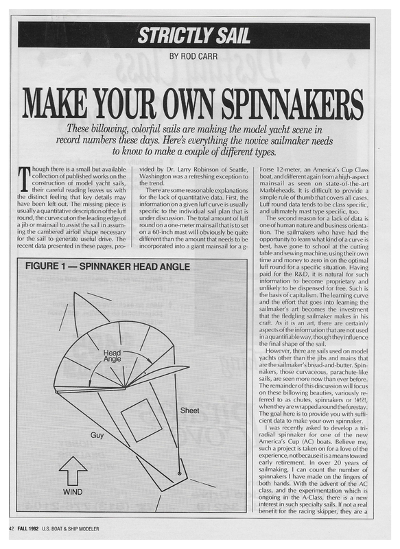
The panels should be joined with a series of zigzag stitches, working about one inch at a time along the seam, then repositioning your finger and the panels for the next inch. Don’t rush, and don’t get emotionally in- volved in each seam. Some of them will inevitably have to be taken apart and put back together once you see the sail flying. Consideration must be given to the angle that the spinnaker will subtend as viewed from above. The larger the head angle, the larger the spinnaker. Too large and the beast becomes hard to fly. I’d suggest that you start at no greater than 80 or 90 degrees for your first experiment. The head angle is shown in Figure 1. The simplest spinnaker to make is a bilateral or two-piece spinnaker. This is sometimes called the “Elephant Behind” variety, due to the shape that results in the vicinity of the center seam if poorly done. Figure 2 shows a generic shape. I’ve pur- posely left it undimensioned to give you the impetus to simply sew one up using curves that you develop. Make it small enough that if it hangs straight down from the masthead, it won’ttouch the water. The exercise will give you some insight into the process. It doesn’t take too much curve in each panel that comes together to produce an angular “corner” for a joint. But the best way to develop a feel for this is to simply do it. While simple to construct, the two-piece spinnaker has limited opportunity for an array of different colors. Spinnaker cloth is very strong compared to the loads it must bear when used on a model yacht. There is no reason to make spinnakers any more complex from a strength standpoint. Most of the more complex spinnakers are made for models because they look like scale renditions of the big boat sails. The stresses on a spinnaker for a 40-footer require that threadlines of the cloth be aligned with the loads the sail has to carry. For a little boat, we never get close to overstressing the cloth. The next level of complexity is the horizontal cut or crosscut developed by Ted Hood. I’ve never made one ofthese, but the horizontal panels give an opportunity to make some eye-catching combinations. The large size of the panels makes it a sure bet that a spinnaker built in this format will come apartanumber oftimes to be adjusted before it assumes the desired shape. Figure 3 shows the panel layout for a crosscut spinnaker. The radial head spinnaker combines a continued on page 62 tal panels. Figure 4 shows the approach to the radial head gores. | have provided the measurements in terms of a value “r’—the radius of the head—and should be ap- proximately equal to the length of the spinnaker poles you will use. AP sat: Sewing the panels together requires minimum tension on the sewing machine. “equator,” which is composed of horizon- | recommend that you lay out the head gore shape on paper and glue it to some © ~ well-defined, spherical head made up of individual gores with a skirt below its 1/8-inch masonite to use as a pattern. The top half of a radial head spinnaker is Bn hand sewing of panels will result in a puckered, dimpled spinnaker that looks like a bad case of terminal cellulite, rather than the smooth, rounded shape that can be admired. \ something you can calculate, and be assured of its shape the first time it is sewn. Then you add the horizontal panels, one at a time, adjusting the taper on the top and bottom of each horizontal panel as you go down. All in all, this variety provides a nice balance between knowing how it will be shaped and also being able to do a dis- tinctive color scheme with the individual panels. In order to align the stresses radiating from each corner of the sail, the tri-radial spinnaker was developed. The options for multi-colored works of art are almost lim- yy maintained with a constant overlap. Free- STRICTLY SAIL continued from page 45 7A gently curved, it is important that when the panels are sewn together, the curve is ri id IQ —¢ 34 19 AVI aliaditi OdIiLet, UA Oe vvay, | (619) 449-1 112 ¢ Fax (619) 449- THE SCALE SHIPYARD FOR THE SCALE’ SHIPMODEL! The leader inaccurate true scale arship hulls and acce: fiberglass hullSfor the static and F model shipbuilder. | through modern\warships, commercial vessels and tugs. USS MASSACHUSETTS BB-59 WITH of marking each patch with P, S and H for port, starboard and head. They all look alike when they are sticking out of a bag, turtle or hole in the deck. A reinforced patch for the retract line is put in the center of the sail. It is the point that if you pull the sail through a ring, all three corners come through the ring together. Dacron on both sides of the sail, and a simple loop of sheet line, wellknotted, will be strong and yet lightweight. The shape of a spinnaker is hinted at by holding the three corners parallel to the floor and letting gravity pull down on the cloth. This is only an approximation. The wind forces that push the sail into its shape do not all act in one direction like gravity. So ultimately, you have to go outside the first helper sit on the ground and hold the mast while the second helper crouches behind him and plays the sheet and guy. PLANS. 1/8″ SCALE 55-1/2″ LGA WITH ‘PLANS. You should walk away and analyze the USS TICONDEROGA CG-47‘CLASS 1/8″ SCALE 70-7/8’7LOA WITH PLANS. U-505 TYPE IX/C GERMAN U-BOAT 1:48 SCALE 63″ LOA WITH CONNING TOWER, PLANS, DIVEPLANES & RUD USS BUILT RS. ANGELES SSN-688 45″ LONG, 4-1/8″ BEAM 1:48 SCALE, 90″ LONG, 8-1/4″ BEAM HULL, SAIL, PLANS, AND DIVEPLANES. Send Dacron patches in all three corners on each side of the sail. Consider the sensibility 1×2-inch pole is a good substitute. Have USS OLIVER HAZARD PERRY FFG-7 1:96 SCALE/ edge using a 3/16-inch zigzag stitch. | put chute to the top of a spare mast; an 8-foot USS ARIZONA BB-39 USS LOS each of the panels. In this configuration, the foot is not very wide. This was done to allow the maximum amount ofadjustment with the spinnaker poles. Too big a foot would be hard to slew from one side to the other, and risks falling into the water ahead of the boat should the wind drop. This sail should remain almost totally out of the water with the spinnaker poles spread wide. If you embark on something like this, be prepared to spend a few weeks. | put about 32 hours into the actual work at the cutting table and sewing machine, plus three or so at the drafting board in preparation. To make a different size, multiply all dimensions by a fraction (your pole length/28). [cut 1/2-inch strips of 2.2-ounce Dacron the length of each side of the spinnaker to use as tabling and reinforcement along the edges. Smaller spinnakers could use proportionally smallertabling. This helps keep the panels from becoming distorted along the free-standing edges of the sail and provides a good anchoring point for the with two willing helpers. Fix the head of the 1/8″ 85″ LOA WITH 5 RIECE SUPERSTRUCTURE MOLDING\& PEANS. 1/8″ SCALE, 76” LONG, Figure 5 shows the individual shapes of grommets that go into the corners. Fold the strip in half, lengthwise, and sew it over the itless here, but the price is paid in having a greatmany panels to sew together. | recently produced a huge one for an AC Class boat, with the “r’ value being 28 inches. seams were adjusted. So once you are satisfied, you can make another one with little fiddling. $6.00 for new 1992 Catalog Listing Fittings and Over 100 Fiberglass Model Ship Hulls | CREDIT CARDS ACCEPTED MINIMUM CHARGE $50.00 THE SCALE SHIPYARD EPT. B 66 ORANGE AVE. #3 LONG BEACH, CA 90805-4146 shape from many different angles. Photographs taken with anormal lens cameraare a help, too. You have, of course, kept careful records of the shape of each panel, and modifications made to them as the § For spinnaker cloth samples, or as a place to send the photos of your latest project, or even if you have a question (SASE please): Rod Carr, 3011-177th Ave. NE, Redmond, WA 98052. ®