- Title. Author. Summary
- Title. Author. Summary
- Title. Author. Summary
- Title. Author. Summary
- Title. Author. Summary

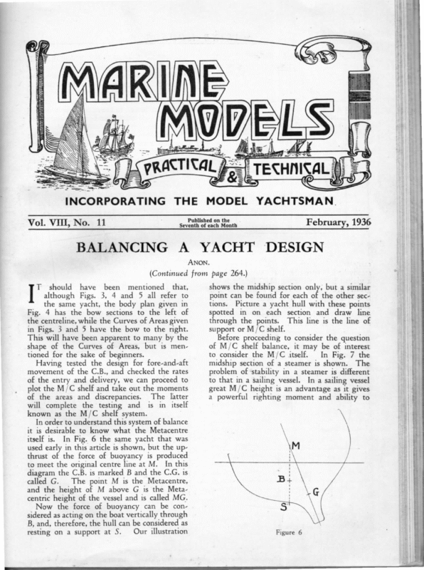
saosin ta fet SUL — te. — —-. – — INCO RPORATING Vol. VIII, No. THE MODEL YACHTSMAN. Published on the Seventh of each Month 11 BALANCING A YACHT February, 1936 DESIGN ANON. thrust of the force of buoyancy is produced to meet the original centre line at M. In this diagram the C.B. is marked B and the C.G. is called G. The point M is the Metacentre, and the height of M above G is the Metacentric height of the vessel and is called MG. Now the force of buoyancy can be considered as acting on the boat vertically through B, and, therefore, the hull can be considered as Our illustration resting on a support at S. Figure 6 ; went —- ae ~cape ee rl * – Picture a yacht hull with these points spotted in on each section and draw line through the points. This line is the line of support or M/C shelf. Before proceeding to consider the question of M/C shelf balance, it may be of interest to consider the M/C itself. In Fig. 7 the midship section of a steamer is shown. The problem of ‘stability in a steamer is different to that in a sailing vessel. In a sailing vessel great M/C height is an advantage as it gives a powerful righting moment and ability to ee Having tested the design for fore-and-aft movement of the C.B., and checked the rates of the entry and delivery, we can proceed to plot the M/C shelf and take out the moments of the areas and discrepancies. The latter will complete the testing and is in itself known as the M/C shelf system. In order to understand this system of balance it is desirable to know what the Metacentre itself is. In Fig. 6 the same yacht that was used early in this article is shown, but the up- point can be found for each of the other sec- tions. ~ the same yacht, the body plan given in Fig. 4 has the bow sections to the left of the centreline, while the Curves of Areas given in Figs. 3 and 5 have the bow to the right. This will have been apparent to many by the shape of the Curves of Areas, but is mentioned for the sake of beginners. shows the midship section only, but a similar a that, 7 .2.2 asdeons mentioned ad been = have bi should —+– T | although Figs. 3, 4 and 5 all refer to = (Continued from page 264.)
MARINE 288 MODELS It will be observed in Fig. 7 that the C.G. is some distance above the C.B. The same vessel is shown heeled in Fig. 8, and it will be apparent that in spite of this the vessel has still a tendency to right herself and is in stable equilibrium at this angle of heel. Of course, if she were heeled to the same angle as a sailing yacht the safety limit would be passed, and the ship turn turtle. The same steamer is shown in Fig. 9, but in this diagram it is assumed that she has a light cargo in her holds and a heavy deck cargo, with the result that the C.G. has been C+E e re.) ul él Figure 7 carry sail. In a steamer which has not the steadying influence of sails the vessel will have a violent jerky roll if the M/C height is too great. In order to get an easy motion the C.G. is therefore placed higher than on a sailing vessel, and in some vessels it has been placed dangerously high and actual losses have been attributable to this fact. Figure 9 raised to such an extent that she has been rendered dangerously tender. At this angle of heel the forces of gravity and buoyancy are combined to capsize the vessel, and she is in unstable equilibrium. From an examination of these diagrams it will be apparent that immediately the M/C falls below the C.G. of the vessel she loses the ability to right herself and will capsize. Another way to state this is to say that a vessel will capsize when heeled to a point when the C.G. is to leeward of the C.B. It will, therefore, be apparent that the M/C height is a direct indication of the stability of a vessel. The position of the upright M/C is the same as that for a low angle of heel, say 3°. When a greater angle of heel is reached its position alters and at extreme angles it falls
M+ W ‘i – <7 w Sao BRE Figure 10 that have been already given it should be quite a simple matter for him to follow it out. The upright waterline is W and the heeled waterline W'. The upright C.B. is B, and the heeled C.B. is B'. The C.G. is marked G and the Metacentre M. The angle of heel is 6. The M/C height is MG. It will be seen that a line has been drawn through G parallel to MB’. The distance between this line and MB’ is represented by A, which is the Righting Arm. Fortunately it is unnecessary for the model designer to know very accurately the M/C height of either a yacht or powerboat as that would entail finding the C.G. which is a very tedious business. The method by which it is ascertained is by tabulating all the component parts of the vessel with their weights and heights above or below LWL. Moments are then taken, and the total of the moments divided by the total weight. This gives the height of the C.G., and its fore-and-aft position is ascertained in a similar fashion. What we do, however, want to know is the C.B. of the whole vessel and individual sec- Having found the C.B. the M/C can easily be found. If a line is drawn through the heeled C.B. perpendicular to the heeled waterline and produced as required to meet the centre line, it will give the M/C for the section. Likewise if it is produced downwards to the skin of the boat it gives the position of the M/C Shelf on the section. In order to ascertain the C.B. of the whole boat, the underwater portions of all the sections between the LWL endings have to be taken off on tracing paper and cut out, as above. Place the sections on top of each other in their exact relative positions and secure in position with small spots of gum. Do not use more gum than is absolutely necessary as its weight might affect the results. Find the C.B. of the whole body by suspending, as explained, for a single section. The C.B. thus found is the transverse C.B. The fore-and-aft position is found by balancing the curve of areas, as explained in the first part of this article. Now the C.B. of the-whole body is the mean of the combined centres of the individual Ee Re Tame a Om ae SEI DP 4 a en anual inte blies YPowncr ari pal a on inal tions. Taking the latter first, place a piece of tracing paper on the body plan and trace the windward side of the heeled section (i.e., the half-section minus the out-wedge). Turn the paper over and being careful that it registers correctly, trace the leeward side (i.e., the halfsection plus the in-wedge). This gives the outline of the whole heeled section. This is cut out with scissors. Next draw a perpendicular line on either the wall or a convenient door. Stick a pin through the top left-hand corner of the section and let it hang down on the line. Of course the pin goes into the top of the line on the wall, and it does not matter whether the top right-hand or left-hand corner is taken first. Draw the vertical on the section. Repeat with the other corner. The point where the verticals intersect is the C.B. Actually what has been done is to find the centre of gravity of the piece of paper which is cut to the shape of the underwater part of the heeled section. Although it is suggested that the balancing points be the top corners, it does not make any difference where abouts the pin is put, as all the verticals will pass through the same central point. In order to get a positive result, however, it is not desirable to take balancing points too near the centre, and also the verticals should cut at about right angles. ge A few experiments with different types of section will soon give the reader a grasp of the different characteristics of different types of boat. For instance, a scow has great initial stability, as indicated by great M/C height at low angles of heel, but as the angle increases the M/C falls rapidly and she loses her stiffness, until the safety limit is reached at a comThe narrow, paratively low angle of heel. deep boat, on the other hand, has far less rises rapidly as initial stability, but the M/C she heels, and her stiffness increases until she is uncapsizable at any ordinary angle of heel. The usual M/C diagram (see Fig. 10) often mystifies the tyro, but with the explanations 289 ye ph oe until the safety limits are reached. The position of the M/C is directly dependent on the actual shape of the hull and the angle of heel. A hull can be designed for which the M/C remains constant over a great range of heeling. MODELS eee o MARINE
290 MARINE sections, and therefore they must all fall in the same line, or as is more likely some sections will have their C.B. to windward and some co leeward of the vessel’s C.B. In the arrangement of these centres lies the secret of M/C Shelf balance, as, if they are wrongly arranged, the whole axis of the boat will twist. The M/C Shelf system of balance was invented by the well-known designer who writes under the pseudonym of *“ Kappa,” and in a letter to the Yachting Monthly published in February, 1934, he outlined his system in 20 points. As the writer sees no possible way of improving this explanation it is quoted below :— (1) A yacht sails mostly on its side, and it is necessary to design the hull in a heeled position. (2) It must not alter course during the pro- cess of heeling, otherwise a trim of sheets and/ or position of the mast suitable for, say, 5 degrees of heel may be quite unsuitable for a heel of, say, 25 degrees. (3) A yacht which complies with condition (2) is said to be balanced, and, if of normal shape, she will be found to balance at intermediate angles. (4) A yacht balanced statically (1e., at rest in still water) will balance dynamically underway as far as can be observed experimentally. (5) The heeled and upright dilaceramats The former exceeds the are not identical. latter by the vertical depressing force from the sails. A heavily-ballasted deep racing yacht will A be depressed in the water as she heels. non-ballasted or lightly-ballasted racing yacht may, however, lift up in the water and float on her side like a bladder. The amount of depression depends, for hulls which are otherwise similar, on— (a) The proportion of total displacement carried as ballast (as high as 80 per cent. in some extreme cases of both yachts and models). (b) The vertical disposition of this ballast. (c) The area of the load water plane. (d) The strength of wind. In light weather at 25° heel the depression is less than at the same angle under a low reefed rig. For normal ballasted racing craft it is sufhcient to assume that the amount of depression is cancelled ‘by the lift of the hull on heeling. (6) By far the largest force acting on the hull of a yacht is the vertical upthrust of the water on the yacht’s bottom, viz., the total MODELS weight plus the vertical depressing force, and it is essential that the application of this force be placed under rigid predetermined control. (7) The employment of calculations for the positions of the heeled centre of buoyancy and the heeled metacentre is to be eek 3 The centres of gravity of displacement, and other curves, should be determined by the poising of thin transparent paper patterns on a knife edge. Otherwise there is a grave risk of the untrained designer being unable to see his design and mould it into shape for columns of figures, and, moreover, the work will become wearisome. (8) The foundation of the design is the vertical plane through the heeled centre of buoyancy parallel with the fore-and-aft axis of the yacht. (9) This foundation must be determined tentatively in the early stages of the design, and the position of the upright transverse metacentre gives a clue to its probable position. This metacentre is well Gelove the waterline in an extreme plank on edge design. It may be on the waterline in a healthy plank on edge design, about one-sixth or one-seventh of the beam above the waterline in a normal racing yacht and as high as the main boom above the deck in an extreme skimming dish. Its vertical height above the upright centre of buoyancy is given by the following rule : — The height of the metacentre above the centre of buoyancy is two-thirds of the sum of the cubes of the half ordinates of the load water plane divided by the sum of the areas of the immersed sectional areas. (10) The above height is independent of the length of the yacht, and a balanced hull may therefore be concertinaed in or out longitudinally, and remain balanced. On the other hand, the beam scale cannot be altered independently of the draught scale, or vice versa, without affecting the balance, and if such alteration is appreciable and necessary involved. the rebalancing of the hull is (11) The longitudinal metacentre may be as high as the mast, and it affects the pitching by the head, etc. It is of no ‘neil in- terest save that its height above the waterline should not be less than the length of the waterline itself, otherwise the yacht may pitchpole on the run—-models have done so. The word metacentre from now onward means the transverse upright metacentre unless otherwise stated.
MARINE MODELS 311 Letters intended for publication must be written on one side of paper only and bear the signatures of writers (not necessarily for publication). Letters should not exceed 300 words in length, if possible. The Editor does not undertake to publish all letters received, nor does he necessarily agree with opinions expressed by Correspondents. ———— | : given in Alan Gerbault’s book. ‘‘ Firecrest ’’ was towed under in French waters, when handed over to the French navy, and she was replaced by a better boat of the Norse type. Models of ‘* Spray,’’ ** Firecrest ’’ and ** Svaap.”’ could be made to sail, but ‘*‘ Tilikum ’’ would be an interesting ornament only.—I am, etc., JOHN A. STEWART. 104, Cheapside Street, Glasgow, C.3. SpA ge ele ay HANDERS Oe Sir,—The lines of ‘* Tilikum ’’ are given in The Venturesome Voyages of Captain Vos. This boat was an Indian canoe, dug out of a solid red cedar log, narrow and crank. For the world voyage she was strengthened and decked; and her remains are now preserved in the grounds of the Crystal Gardens, Victoria, B.C. The design of *‘ Spray ’’ will be found in Sailing Alone Around the World, by Capt. Joshua Slocum. ** Spray ’’ was very broad and rather shallow, with sections like those_of a Cape Cod cat boat. Both boats are of a capsizable type, and would make poor sailing models, even if fitted with bulb keels as an extra; but they would be of great interest as museum pieces. Captain Johnson would have more satisfaction in making a modei of ‘* Svaap,’ the Alden-designed ketch, sailed round the world by Wm. A. Robinson. The lines are given in Deep Water and Shoal. ** Firecrest "’ was simply an old-fashioned cutter by Dixon Kemp, and I think a sketch plan was EEE) -Se + SINGLE t EE) 6a NOTED t Se a ey = to windward at all. All my designs are supposed to use the rudder to windward—yet one owner states that he thinks it poor policy! Of course, his model was beaten, although she won all leeward boards. How can such ideas get into anyone’s head? A new steering gear has recently been perfected by me, and the model owners think it a knockout, as it can be used with a vane, keeping the mast in the same position. Personally I never thought much of a vane, as there are more effective means to prevent stalling employed in the new gear (patent pending). There are so many more interesting things in Colonel Holden's letter, and in the design of ** Naiad,’’ that will be reserved to a separate article. There is, for instance, the shelf balance, so-called, that entails no balance at all, the Curve of Areas that does not give a good form, the C.L.R. that does not wander as supposed in text-books, and many, many other wrong conceptions that would fill volumes. Yours very truly, C. O. LILJEGREN. 102, Kemper Street, Wollaston, Mass., U.S.A. SEE ‘*‘ NAIAD " EEA A-CLASS Sir,—The model fraternity all over the world should feel grateful to Colonel Holden for his contribution in the October issue of MARINE MODELs, entitled ‘* Fleetwood Regatta.’’ To date, the writer has seen no comments that the interesting article so well deserves. He brings up many controversial questions, usually taken for granted by text-book authors and professors, etc., who should know better. To begin with, let me state most emphatically that no craft with a canoe stern, as ‘* Naiad,’’ can ever be fast except in very light airs. Hundreds of useless racing yachts could be quoted to prove this sweeping statement—from America’s Cup Yachts to the smallest model yachts. But as *“ Naiad ’’ is fast, how very good must not her general form, proportions, and dimensions be, to counterbalance the negative influence of her canoe stern! How much better her behaviour if fitted with a regular yacht counter and a narrow transom! Any designer who shapes a canoe stern on his racing yachts does not know the very first principle of speed, that can be formulated thus: The after end of any craft built for speed, air or water, must be made conical, and end in straight lines best represented by diagonals. For straight lines cause no acceleration, and where there is no acceleration there is no loss of force. Hence the maximum return is gotten from the afterbody and the highest speed possible, other things being equal. This principle is accepted universally as a hydraulic law as basic as gravitation. If someone will build a ** Naiad *’ with conical counter, he would get a faster model, except in very light airs. Another question that puzzles model men. is the fact that a heavy displacement model is fastest in light airs. This is very simply explained, for of two similar forms having the same overall dimensions, the heavier one always has the smallest wetted surface. In light airs with low speeds, wetted surface decides the resistance of the model, and hence the speed. This does not mean that the speed of ‘* Naiad,’’ for instance, or any model, is increased if weight is added—quite the contrary, because the overall dimensions become larger, and generally the sail area must be reduced to suit. Colonel Holden touches on using the rudder to windward—a method that I have preached to American model men for ten years—until recently without success. The folly of not making use of rudder to increase lateral resistance, when most wanted, and to prevent stalling, should be evident to every model man—yet not one seems to understand it. Fancy a real yacht going to windward without a rudder, and all the time either too full, or stalling. The wonder is that a model can sail
290 MARINE sections, and therefore they must all fall in the same line, or as is more likely some sections will have their C.B. to windward and some to leeward of the vessel’s C.B. In the arrangement of these centres lies the secret of M/C Shelf balance, as, if they are wrongly arranged, the whole axis of the boat will twist. The M/C Shelf system of balance was invented by the well-known designer who writes under the pseudonym of “ Kappa,” and in a letter to the Yachting Monthly published in February, 1934, he outlined his system in 20 points. As the writer sees no possible way of improving this explanation it is quoted :— ne (1) A yacht sails mostly on its side, and it is necessary to design the hull in a heeled position. (2) It must not alter course during the pro- cess of heeling, otherwise a trim of sheets and/ or position of the mast suitable for, say, 5 degrees of heel may be quite unsuitable hoe a heel of, say, 25 degrees. (3) A yacht which complies with condition (2) is said to be balanced, and, if of normal shape, she will be found to balance at inter- mediate angles. (4) A yacht balanced statically (1e., at rest in still water) will balance dynamically underway as far as can be observed experimentally. (5) The heeled and upright displacements The former exceeds the are not identical. latter by the vertical depressing force from the sails. A heavily-ballasted deep racing yacht will A be depressed in the water as she heels. non-ballasted or lightly-ballasted racing yacht may, however, lift up in the water and float on her side like a bladder. The amount of depression depends, for hulls which are otherwise similar, on— (a) The proportion of total displacement carried as ballast (as high as 80 per cent. in some extreme cases of both yachts and models). (b) The vertical disposition of this ballast. (c) The area of the load water plane. (d) The strength of wind. In light weather at 25° heel the depression is less than at the same angle under a low reefed rig. For normal ballasted racing craft it is sufficient to assume that the amount of depression is cancelled ‘by the lift of the hull on heeling. (6) By far the largest force acting on the hull of a yacht is the vertical upthrust of the water on the yacht’s bottom, viz., the total MODELS weight plus the vertical depressing force, and it is essential that the application of this force be placed under rigid predetermined control. (7) The employment of calculations for the positions of the heeled centre of buoyancy and the heeled metacentre is to be avoided. The centres of gravity of displacement, and other curves, should be determined by the poising of thin transparent paper patterns on a knife edge. Otherwise there is a grave risk of the untrained designer being unable to see his design and mould it into shape for columns of figures, and, moreover, the work will become wearisome. (8) The foundation of the design is the vertical plane through the heeled centre of buoyancy parallel with the fore-and-aft axis of the yacht. (9) This foundation must be determined tentatively in the early stages of the design, and the position of the upright transverse metacentre gives a clue to its probable position. This metacentre is well below the waterline in an extreme plank on edge design. It may be on the waterline in a healthy plank on edge design, about one-sixth or one-seventh of the beam above the waterline in a normal racing yacht and as high as the main boom above the deck in an extreme skimming dish. Its vertical height above the upright centre of buoyancy is given by the following rule : — The height of the metacentre above the centre of buoyancy is two-thirds of the sum of the cubes of the half ordinates of the load water plane divided by the sum of the areas of the immersed sectional areas. (10) The above height is independent of the length of the yacht, and a balanced hull may therefore be concertinaed in or out longitudinally, and remain balanced. On the other hand, the beam scale cannot be altered independently of the draught scale, or vice versa, without affecting the balance, and if such alteration is appreciable and necessary the rebalancing of the hull is involved. (11) The longitudinal metacentre may be as high as the mast, and it affects the pitching by the head, etc. It is of no immediate interest save that its height above the waterline should not be less than the length of the waterline itself, otherwise the yacht may pitchpole on the run—models have done so. The word metacentre from now onward means the transverse upright metacentre unless otherwise stated.
MARINE (12) The height of the metacentre above the centre of buoyancy is very sensitive to alterations of the beam scale—other things being equal, it varies as the square of the beam. The amount the centre of buoyancy moves to leeward on heeling is similarly susceptible, and therefore readily adjustable—together with the plane of reference which passes through it— the foundation of the design. (13) In balancing an existing design, the position of the metacentre must be determined by the Rule in (9). In commencing a new design a position for the metacentre must be chosen tentatively, vide (9), and the yacht roughly sketched out by freehand heeled with the lee rail on the water. The transverse position of the heeled centre of buoyancy should be determined by cutting patterns in transparent paper (cardboard is far too clumsy) and transposing them on each other centrally, securing them to each other by small spots of gum. Then all together (i.e., the replicas of all the heeled underbody sections) they are poised over a knife edge laid perpendicularly to the heeled waterline. The line of the knife edge passes through the heeled centre of buoyancy and the heeled metacentre. The vertical positions of these centres are of no immediate interest—they need not be determined for the present purpose. (14) The fore-and-aft line underneath the centre of buoyancy is the line of the reference plane and is the mean metacentric axis. (15) ‘The fore-and-aft wavy line which passes under the CG of each immersed heeled section (found by poising the patterns individually) is the line of the wooden blocks, as it Were, under the belly of the yacht, which take her weight if she were imagined to be heeled in a dry dock. It is called the metacentric shelf. The distance the shelf is offset from the axis at any station is called the discrepancy. (16) If a plumb-bob be dropped from the upright metacentre and it passes through the heeled centre of buoyancy, the hull is called a ** metacentroid.”’ If it does not so pass it is recommended that adjustments be made to the height of the metacentre and /or the plane of reference. The former can be adjusted by change in the beam scale, vide (12), and/or by altering the displacement. It does not’ follow that the upright and heeled metacentres are coincident. They are MODELS 291 in the same vertical line, but the latter may be above or below the former without affecting the balancing. (17) In a balanced hull it generally happens that a portion amidships carries a considerable proportion as a keel appendage, whereas the forward and after portions contain relatively little, or even none. The line of blocks, 1e., the metacentric shelf, will lie to windward of the plane of reference, the metacentric axis abreast the main belly of the hull. The shelf forward will lie to leeward, and, similarly, so will the after portion of the shelf, to a greater extent, however, as generally the body abaft the keel is smaller than the fore body. Collectively the total upthrust passes through the plane of neference or axis. It is essential that the moments of the fore body and after body to leeward be about equal, and it follows that they are collectively equal to the moment on the windward side. The metacentric method enables such necessary adjustments to be made with precision. It is extremely doubtful if this could be effected by the employment of cumbersome tables of figures or by trigonometrical calculations. (18) The heeled and upright positions of the centre of buoyancy must be in the same transverse plane. The employment of this method shows clearly which must be moved forward, which moved aft, or whether both require moving forward or aft. (19) The fore-and-aft position of the centre of buoyancy cannot be fixed arbitrarily—the method of balance determines its position, which varies for different forms of keel and/or under body. (20) Alterations of course after heeling may be due to excessive deadwood, the buckling of the mast, the collapsing of fore stays, etc., and any such alteration must not be regarded as a defect in balance. * * * * It will be seen that a number of “* Kappa’s ” points have already been covered by the writer, also that another balancing method of finding the C.B. is recommended, but in practice the latter amounts to virtually the same thing. Almost every designer has his own methods. and routine, and to the novice, at all events, it may be of interest to detail those followed by the writer.
290 MARINE sections, and therefore they must all fall in the same line, or as is more likely some sections will have their C.B. to windward and some to leeward of the vessel’s C.B. In the arrangement of these centres lies the secret of M/C Shelf balance, as, if they are wrongly arranged, the whole axis of the boat will twist. The M/C Shelf system of balance was invented by the well-known designer who writes under the pseudonym of “ Kappa,” and in a letter to the Yachting Monthly published in February, 1934, he outlined his system in 20 points. As the writer sees no possible way of improving this explanation it is quoted below :— (1) A yacht sails mostly on its side, and it is necessary to design the hull in a heeled position. (2) It must not alter course during the process of heeling, otherwise a trim of sheets and/ or position of the mast suitable for, say, 5 degrees of heel may be quite unsuitable for a heel of, say, 25 degrees. (3) A yacht which complies with condition (2) is said to be balanced, and, if of normal shape, she will be found to balance at intermediate angles. (4) A yacht balanced statically (1e., at rest in still water) will balance dynamically under- way as far as can be observed eee eeatallys (5) The heeled and upright displacements The former exceeds the are not identical. latter by the vertical depressing force from the sails. A heavily-ballasted deep racing yacht will A be depressed in the water as she heels. non-ballasted or lightly-ballasted racing yacht may, however, lift up in the water and float on her side like a bladder. The amount of depression depends, for hulls which are otherwise similar, on— (a) The proportion of total displacement carried as ballast (as high as 80 per cent. in some extreme cases of both yachts and models). (b) The vertical disposition of this ballast. (c) The area of the load water plane. (d) The strength of wind. In light weather at 25° heel the depression is less than at the same angle under a low reefed rig. For normal ballasted racing craft it is sufficient to assume that the amount of depression is cancelled by the lift of the hull on heeling. (6) By far the largest force acting on the hull of a yacht is the vertical upthrust of the water on the yacht’s bottom, viz., the total MODELS weight plus the vertical depressing force, and it is essential that the application of this force be placed under rigid predetermined control. (7) The employment of calculations for the positions of the heeled centre of buoyancy and the heeled metacentre is to be Eames The centres of gravity of displacement, and other curves, should be determined by the poising of thin transparent paper patterns on a knife edge. Otherwise there is a grave risk of the untrained designer being unable to see his design and mould it into shape for columns of figures, and, moreover, the work will become wearisome. (8) The foundation of the design is the vertical plane through the heeled centre of buoyancy parallel with the fore-and-aft axis of the yacht. (9) This foundation must be determined tentatively in the early stages of the design, and the position of the upright transverse metacentre gives a clue to its probable position. This metacentre is well below the waterline in an extreme plank on edge design. It may be on the waterline in a healthy plank on edge design, about one-sixth or one-seventh of the beam above the waterline in a normal racing yacht and as high as the main boom above the deck in an extreme skimming dish. Its vertical height above the upright centre of buoyancy is given by the following rule : — The height of the metacentre above the centre of buoyancy is two-thirds of the sum of the cubes of the half ordinates of the load water plane divided by the sum of the areas of the immersed sectional areas. (10) The above height is independent of the length of the yacht, and a balanced hull may therefore be concertinaed in or out longitudinally, and remain balanced. On the other hand, the beam scale cannot be altered independently of the draught scale, or vice versa, without affecting the balance, and if such alteration is appreciable and necessary the rebalancing of the hull is involved. (11) The longitudinal metacentre may be as high as the mast, and it affects the pitching by the head, etc. It is of no pias in- terest save that its height above the waterline should not be less than the length of the waterline itself, otherwise the yacht may pitchpole on the run—-models have done so. The word metacentre from now onward means the transverse upright metacentre unless otherwise stated.
too clumsy)\ aa transposing them on each other centrally, securing them to each other by small spots of gum. Then all together (i.e., the replicas of all the heeled underbody sections) they are poised over a knife edge laid perpendicularly to the heeled waterline. The line of the knife edge passes through the heeled centre of buoyancy and the heeled metacentre. The vertical positions of these centres are of no immediate interest—they need not be determined for the present purpose. (14) The fore-and-aft line underneath the centre of buoyancy is the line of the reference plane and is the mean metacentric axis. (15) ‘The fore-and-aft wavy line which passes under the CG of each immersed heeled section (found by poising the patterns individually) is the line of the wooden blocks, as it Were, under the belly of the yacht, which take her weight if she were imagined to be heeled in a dry dock. It is called the metacentric shelf. The distance the shelf is offset from the axis at any station is called the discrepancy. (16) If a plumb-bob be dropped from the upright metacentre and it passes through the eet centre of buoyancy, the hull is called ‘* metacentroid.” "if it does not so pass it is recommended that adjustments be made to the height of the metacentre and/or the plane of reference. The former can be adjusted by change in the beam scale, vide (12), and/or by altering the displacement. It does not’ follow that the upright and heeled metacentres are coincident. They are 291 lations. (18) The heeled and upright positions of the centre of buoyancy must be in the same transverse plane. The employment of this method shows clearly which must be moved forward, which moved aft, or whether both require moving forward or aft. (19) The fore-and-aft position of the centre of buoyancy cannot be fixed arbitrarily—the method of balance determines its position, which varies for different forms of keel and/or under body. (20) Alterations of course after heeling may be due to excessive deadwood, the buckling of the mast, the collapsing of fore stays, etc., and any such alteration must not be regarded as a defect in balance. * * * * It will be seen that a number of “ Kappa’s’ points have already been covered by she writer, also that another balancing method of finding the C.B. is recommended, butin practice the latter amounts to virtually the same thing. Almost every designer has his own methods. and routine, and to the novice, at all events, it may be of interest to detail those followed by the writer. ts a in the same vertical line, but the latter may be above or below the former without affecting the balancing. (17) In a balanced hull it generally happens that a portion amidships carries a considerable proportion as a keel appendage, whereas the forward and after portions contain relatively little, or even none. The line of blocks, 1e., the metacentric shelf, will lie to windward of the plane of reference, the metacentric axis abreast the main belly of the hull. The shelf forward will lie to leeward, and, similarly, so will the after portion of the shelf, to a greater extent, however, as generally the body abaft the keel is smaller than the fore body. Collectively the total upthrust passes through the plane of neference or axis. It is essential that the moments of the fore body and after body to leeward be about equal, and it follows that they are collectively equal to the moment on the windward side. The metacentric method enables such necessary adjustments to be made with precision. It is extremely doubtful if this could be effected by the employment of cumbersome tables of figures or by trigonometrical calcu- ee eer (12) The height of the metacentre above the centre of buoyancy is very sensitive to alterations of the beam scale—other things being equal, it varies as the square of the beam. The amount the centre of buoyancy moves to leeward on heeling is similarly susceptible, and therefore readily adjustable—together with the plane of reference which passes through it— the foundation of the design. (13) In balancing an existing design, the position of the metacentre must be determined by the Rule in (9). In commencing a new design a position for the metacentre must be chosen tentatively, vide (9), and the yacht roughly sketched out by freehand heeled with the lee rail on the water. The transverse position of the heeled centre of buoyancy should be determined by cutting patterns in transparent paper(cardboard is far MODELS aE er gn MARINE
292 MARINE Having decided on the main dimensions of the yacht, the positions for the greatest depth of the canoe body and maximum beam are settled. The profile of the canoe body, line of greatest beam (which is not necessarily the deckline), and raked master section are put in. The author keeps quite a number of statistics of various craft, and at this point usually takes out the Midship Coefficient and compares it with others. The bilge diagonal follows and, in due course, the canoe body of the boat is completed. MODELS A FINE MODEL STEAM YACHT The displacement and C.B. are now computed without keel, and the Curve of Areas drawn. As one knows approximately what the displacement of the keel will amount to, one can see whether the design is about right in this respect. The C.B. of the canoe body will serve as a guide when planning the keel. The Curve of Areas serves to gauge the rates of the canoe body. The Block and Prismatic Coefficients are then taken out and compared with similar boats. If one has data of known boats for comparison, this is a valuable indication of a yacht’s form. The keel is now put in and the design is ready for testing. The total displacement is calculated, and then the routine described in this article is carried out. When the hull has been balanced satisfactorily, the Sail Plan is made. The final step is to calculate the lead keel and strike the leadline. This all sounds a lengthy process, but at the end the designer should have a pretty good idea of how his yacht will perform, and a little extra time and trouble given to the design at these stages will be found to recompense the designer by improved results. Other designers, no doubt, have other methods which possibly are better or less cumbersome than the above. Whatever method or order of operation is pursued, however, the one essential is that the result must be a balanced design. The method of balancing the rates known as Volumetric balance is a very close check on the underwater body and top-sides and, as the mean of the windward and leeward halfsections is used, this in itself practically ensures the axis keeping a form that will not turn the boat from its course. With the final test provided by the M/C Shelf, there should be no excuse for a designer producing an unbalanced design. Photo: L. J. French MODEL Owner: S.Y. *‘ LADY GAY” F. Markham (Victoria M.S.C.) A Steam Yacht makes an excellent prototype for the model steamship builder. These vessels are usually of moderate size, and the deck details comparatively simple, while the hulls have graceful lines and are easily driven. The model depicted is exceptionally realistic in appearance, and is a beautiful example of her type. She is powered with a Stuart twincylinder engine, boiler and blowlamp.
then round the sheave at the top of the track- way at T, then to the under-side of the first sheave in the cradle, over the top of the next two sheaves, and so to the boat shackle. Note: The cradle sheaves are inside the hollow arms, as clearly shown in Fig. 126. Another wire rope, for securing the boat when in the inboard position, is anchored at a point on the trackway below the top sheave of the * falls.” This wire rope is shown in heavy dotted lines, so let us follow its course. From its anchorage point it runs to a grip fitting on the port side of the life-boat, near the bow, then across to a similar grip on the starboard side, then round the outside of the boat to its keel, and, finally, to a trigger release at R. Note: There is a wooden chock to take the boat’s keel at the lower end of the cradle, which is not shown in the drawing. The trigger R is a small lever with a quick release. As soon as this lever is pulled it releases the wire rope so that when the falls are freed and the cradle runs down the trackway to the outboard position, the boat will swing clear vertically. In our drawing the ee ata ee cradles to be fitted with rollers inside the trackways. Cradles without outside rollers are old types and the model shipbuilder must acquaint himself with the correct type used on the prototype he is modelling. The same remark applies to the actual method of fitting the davits. For example, notice how the trackways are stayed and supported in Fig. 122 in the last issue of MARINE MopELs. Some ships have suitable deck houses which offer obvious supporting points, while other ships have not, and so on. The drawing (Fig. 123) is an up-to-date modern lay-out, which the writer has arranged as suitable for model work. The wire rope and fixings are shown in heavy black so that its lead can be easily traced from the hand winch to the boat itself. Let us follow it. From the hand winch located on the top of the deckhouse D it runs through a deck sheave whose axis is inclined at right angles to the head of the trackway, boat and cradle are shown in the outboard position in dotted lines ready for loading at the boat deck level B. The operating winch may be either handpower or mechanical, but is usually both. Fig. 124 illustrates the correct curve of the trackway and its angle, which should be 30: degrees. Fig. 1244 shows a section of the trackway, which is constructed of channel steel with suitable distance pieces, the two sides being rigidly secured together by welded and riveted straps. The trackways are fitted with curtain plates at deck level for rigid attachment, but for model purposes two bolts passing through these and the ship’s side, fitted with nuts upon the inside, will make a good job, as. shown in Fig. 123. There are several ways of making these trackways, and the reader will probably choose the method that appeals to his skill. If a large number are required, it might be worth while to make formers and bend up lengths of heavy tinplate or light steel strip, which should be formed to the correct angle by being bent HOT, by means of a male and female die, using the vyce as a screw-press for the purpose. Another way would be to build them up from brass strip, soldering the ‘ channel flanges” into position. In this method the curved sides should be cut from sheet brass, one after another, so that there will not be much waste of material; a master curve must be made first. The flanges can then be soldered into position easily and any superfluous solder filed away to make a neat job. The curtain plate, top sheave and housing can then be soldered into their respective positions and, if a real strong job is required, a few rivets can be used in addition. The top sheave and housing are shown in the enlarged sketch (Fig. 125). The cradles (Fig. 126) can be made from two pieces of brass sheet and must be exact counterparts of each other. Here, again, it will be better to make a master, from which a number can be marked out and cut. os Welin-Maclachlan aot of b type eG rg em latest es the — a aeares N | Gravity Davits provision is made for the = Tes age (Continued from page 275.) er FITTINGS By A. P. Isarp, A.M.I.Mech.E. phtlg ihe al AND este gee SHIP win Peer STEAMER MODEL — MAKE : TO 293 OE 2 rept Air HOW MODELS ee a MARINE
294 MARINE. MODELS LS di ip i FIG.125. F'G. 126. : F1G.124. These must be properly spaced to take the sheaves, and fixed with distance pieces of solid brass at the bottom and top, the whole being sweated together and/or riveted, and the outsides cleaned off by filing. The master should have the holes for all the sheave pins marked out and drilled, so that it can be held against one of the side pieces to act as a guide, and the drill put through. The master should be made of steel plate, and, to prevent the holes or its edge becoming worn and spoiling its accuracy, it should be case-hardened: This is only a few minutes’ job and well worth while, but be sure it is accurate first, as afterwards . The sheaves are easily turned up from brass rod and drilled for their pins in one setting in the lathe. They should be an easy fit, but there must be no side play, as otherwise they might cant over and ultimately jam. The cradle rollers should be an easy fit within the channel of the trackway, but here again there must be no undue side play. They should run up and down nicely, remembering that your model life-boats will not weigh much, and they must function by their weight when the “ falls” are released. This should prove an interesting fitting to make, and, if made carefully, should work like its prototype. (To be continued.)
MARINE g » ES % tha) Sy ; MODELS 25 295 iE % Sse ss s ie. : tie. f 4 =< , RS mealies, o| o eee ions \ Sea Soul Yue SUAS GSU G4; TAN SS TESCO ls DOYS STEAM 1. 2. 3. | PES Steam Pipe and Union. Nozzle Lock Nut. Steam Nozzle. as ee BILGE EJECTOR 4. Body of Ejector. 5 & 6. Alternative Delivery Connections. 7. Inlet Cap with Gauze Strainer. onan Fe Dy. dent of the Club, and Councillor Hubert W. Fane, J.P., and Alderman H. V. Kenyon, M.B.E., J.P., Patrons, had again consented to continue. in their respective offices for the ensuing year, and he felt that with such local support, and members’ enthusiasm, they could approach the coming season with every confidence. He also intimated that the present membership was greater than the Club had ever known. The officers as last re-appointed en bloc:— Commodore: dore: Mr. Mr. J. Wilby. W. year T. were Parry. Executive: unanimously Vice-Commo- Messrs. W. But- ler, R. A. R. Cooke, R. S. Every, W. F. McClelland. Hon. Secretary and Treasurer: Mr. F. H. Lambert, 60, Hogarth Road, S.W.5. The following events were arranged for 1936:— Apr. May 5. 3. 24. June 14. 21. July 5. 19. Sept. 6. 20. Oct. 4. 18. Steering Event. Nomination Event. Round the Pond Race. Grand Regatta and Valkyria Cup. Nomination Event. M.P.B.A. Regatta. Steering Event. Steering Event. Nomination Event. Steering Event. Nomination Event. In connection with the above events, there are the Capstan Cup and the Efficiency Cup, and the Chairman announced at the meeting that he was presenting another Cup to the Club, to be known as the ‘* Parry ’’ Trophy, and to be competed for by displacement boats, provided same are not driven by either flash steam or petrol. The following prizes were presented to the prize- winners for 1935:— Mr. C. Burrows—Round the Pond Race, | First; Nomination Events, | First, 1 Second; Steering Event, | First. MODEL YACHTING ASSOCIATION (Concluded from page 309.) It will be noticed that the Provincial Clubs are well represented in the new Council. The remaining item on the Agenda was the adoption of the revised Sailing Rules. The proposed changes were in many cases somewhat drastic and a lengthy discussion resulted, lasting two hours or more before every point was thrashed out. Thanks to the circulation of the proposed rules prior to the Meeting, the members had been able to give due consideration to the matter, and very little time was wasted. Ultimately the Rules were passed for printing. It is pipe to give the changes in extenso here, but the Sailing Rules will be put into the printer’s hands immediately and should shortly be available for distribution. As the changes are considerable, every club official and skipper should secure a copy and study it prior to the opening of the racing season—thus queries and disputes will be avoided. The Meeting closed with a vote of thanks to the Chairman. MODEL SAILING CRAFT By W.J. DANIELS and H. B. TUCKER. Profusely Illustrated with 7 Complete Designs, 163 Diagrams and numerous Photographs. Price 25/-, postage 9d. The Best Textbook for Model Yachtsmen. ORDER YOUR COPY FROM: Marine Models Publications, Ltd., 52, Fetter Lane, London, E.C.4 –
MODELS 311 Letters intended for publication must be written on one side of paper only and bear the signatures of writers (not necessarily for publication). Letters should not exceed 300 words in length, if possible. The Editor does not undertake to publish all letters received, nor does he necessarily agree with opinions expressed by Correspondents. A-CLASS ‘** NAIAD ” Sir,—The model fraternity all over the world should feel grateful to Colonel Holden for his con- tribution in the October issue of MARINE MODELs, entitled ** Fleetwood Regatta.’’ To date, the writer has seen no comments that the interesting article so well deserves. He brings up many controversial questions, usually taken for granted by text-book authors and professors, etc., who should know better. To begin with, let me state most emphatically that no craft with a canoe stern, as ** Naiad,’’ can ever be fast except in very light airs. Hundreds of useless racing yachts could be quoted to prove this sweeping statement—from America’s Cup Yachts to the smallest model yachts. But as ** Naiad ’’ is fast, how very good must not her general form, proportions, and dimensions be, to counterbalance the negative influence of her canoe stern! How much better her behaviour if fitted with a regular yacht counter and a narrow transom! Any designer who shapes a canoe stern on his racing yachts does not know the very first principle of speed, that can be formulated thus: The after end of any craft built for speed, air or water, must be made conical, and end in straight lines best represented by diagonals. For straight lines cause no acceleration, and where there is no acceleration there is no loss of force. Hence the maximum return is gotten from the afterbody and the highest speed possible, other things being equal. This principle is accepted universally as a hydraulic law as basic as gravitation. If someone will build a ** Naiad ’’ with conical counter, he would get a faster model, except in very light airs. Another question that puzzles model men. is the fact that a heavy displacement model is fastest in light airs. This is very simply explained, for of two similar forms having the same overall dimensions, the heavier one always has the smallest wetted surface. In light airs with low speeds, wetted surface decides the resistance of the model, and hence the speed. This does not mean that the speed of ‘* Naiad,’’ for instance, or any model, is increased if weight is added—quite the contrary, because the overall dimensions become larger, and generally the sail area must be reduced to suit. Colonel Holden touches on using the rudder to windward—a method that I have preached to American model men for ten years—until recently without success. The folly of not making use of rudder to increase lateral resistance, when most wanted, and to prevent stalling, should be evident to every model man—yet not one seems to understand it. Fancy a real yacht going to windward without a rudder, and all the time either too full, or stalling. The wonder is that a model can sail to windward at all. All my designs are supposed to use the rudder to windward—yet one owner states that he thinks it poor policy! Of course, his model was beaten, although she won all leeward boards. How can such ideas get into anyone’s head? A new steering gear has recently been perfected by me, and the model owners think it a knockout, as it can be used with a vane, keeping the mast in the same position. Personally I never thought much of a vane, as there are more effec- tive means to prevent stalling employed in the new gear (patent pending). There are so many more interesting things in Colonel Holden’s letter, and in the design of *‘ Naiad,’’ that will be reserved to a separate article. There is, for instance, the shelf balance, so-called, that entails no balance at all, the Curve of Areas that does not give a good form, the C.L.R. that does not wander as supposed in text-books, and many, many other wrong concep- tions that would fill volumes. Yours very truly, C. O. LILJEGREN. 102, Kemper Street, Wollaston, Mass., U.S.A. NOTED SINGLE HANDERS Sir,—The lines of ‘* Tilikum ”’ are given in The Venturesome Voyages of Captain Vos. This boat was an Indian canoe, dug out of a solid red cedar log, narrow and crank. For the world voyage she was strengthened and decked; and her remains are now preserved in the grounds of the Crystal Gardens, Victoria, B.C. The design of ** Spray “’ will be found in Sailing Alone Around the World, by Capt. Joshua Slocum. ** Spray “’ was very broad and rather shallow, with sections like those_of a Cape Cod cat boat. Both boats are of a capsizable type, and would make poor sailing models, even if fitted with bulb keels as an extra; but they would be of great interest as museum pieces. Captain Johnson would have more satisfaction in making a modei of ** Svaap,’ the Alden-designed ketch, sailed round the world by Wm. A. Robinson. The lines are given in Deep Water and Shoal. ‘* Firecrest ‘’ was simply an old-fashioned cutter by Dixon Kemp, and I think a sketch plan was given in Alan Gerbault’s book. ‘‘ Firecrest ’’ was towed under in French waters, when handed over to the French navy, and she was replaced by a better boat of the Norse type. Models of **‘ Spray,’’ ** Firecrest ’’ and ‘* Svaap.”’ could be made to sail, but ‘* Tilikum ’’ would be an interesting ornament only.—I am, etc., JOHN A. STEWART. 104, Cheapside Street, Glasgow, C.3.
312 MARINE MODELS BLUE PRINTS FOR DESIGNS SHIP MODELLERS en BLUE PRINTS OF SS ee eT > MODEL YACHTS A-CLASS. ** Chloris ”’* (New M.M. Design). Half-size with full- size Body Plan, 15/-. * Courtesy,”* A. W. ame 12/6 – size. “ Elusive,”+ Herbert Almond- Halteien, 12) 6-METRES. “ Debutante,”* A. W. Littlejohn. “ Joyce,”+ (New Design). 10-RATER. “ Beroe ’’**s (New M.M. Design). 3 ** Evadne Plan, 15/-. with ey Soe -size Body Plan, 15/-. ”* (M.M. Design). East Indiaman, drawn by G. W. Munro. Hull lines and general details (fin. scale). Rigging and Sail plan (fin. scale). ©The two sheets, 17/6 post free. Cunard S.S. “ Britannia’’ (1840), drawn by H. B. Tucker. Hull lines, general details and Rigging scar ay Body Mounts Bay (Penzance) Lugger. Plans of typical boat, taken from authentic Builder’s Half-Model. Scale lin. = 1ft., 6/6 post free. “Flying Spray,”* A. W. Littlejohn. Half-size, 12/6. “ Leonora,”* W. J. Daniels. Full-size, 21/-. “ Stella ’’* (Sharpie) W. J. Daniels. Full-size, 15/-. plan (fin. scale). Two sheets 10/6 post free. Four Masted Barque “ Buteshire ” (1888), drawn by G. W. Munro. Profile, lines and deck plan, 7s. 6d. Rigging and Sail plan, 7/6. The two sheets, 12/6 post free. SHORTLY READY. Four Masted Barque “Lawhill” (1892), drawn by G. W. Munro. 36in. RESTRICTED CLASS. * Eudora ”* (M.M. Design). “ Babette I,”+ W. J. Daniels. roti, 10/6. *¢ Babette II,”* W. J. Daniels. 30in. RESTRICTED “Jenny Wren,”* CLASS. A. W. Littlejohn. Full-size, 8/6. 24in. L.O.A. Full-size, 5/6. “ Tomtit,”+ A. W. Littlejohn. Binding Cases. Vols. I, II or III complete with Title Page and Index. Binding Cases Vols. IV, V, Vi and VII. Price 2/- post free. MARBLEHEAD 50—800. ** Pocahontas,”* by W. J. Daniels, * Fin-and-skeg. Full-size, 20/-. MODEL MOTOR YACHT. Full- CROSS-CHANNEL STEAMER. “ Maid of Rutland.” Typical Design with Arrangement Plan. 1-metre long. Full-size Plans, 6/6. RACING HYDROPLANE. Hull design by Reg. W. Lance. “Flying Fish.” Half-size with full-size Body Plan, 4/6. FLASH STEAM ENGINE. For metre Hydroplane, by J. Vines. Design twice full-size, to show detail, 3/6. Vols. IV and V, 30/-; Vols. VI and VII, 12/6, post free. We can occasionally supply copies of earlier Volumes. Prices on application. size Plans, 8/6. 1-METRE Binding, Vols. I, II, III, IV, V, V1 or VII (including case), 6/- post free. Bound Volumes. + Full Keel. “ Brunhilde ” (M.M. Design), 40in. long. Volumes I—V were published under the title of “‘ The Model Yachtsman.” Back Numbers. Vol. I. Nos. 1 and 2, 1/1; Nos. 4 and 5, 2/6; No. 6, 1/7; No. 8, 3/-; No. 9, 2/6; No. 10, one only, 7/6; Nos. 11 and 12, 1/7; Vol. II, No. 1, 2/6; Nos. 2—5, 1/1; No. 6, 7/6; No. 7, 1/1; Nos. 8 and 9, 1/7; Nos. 10—12, 1/1. Vol. III, No. 1, 2/6; No. 2, 7/6; No. 3, 2/6; No. 4, 5/-; Nos. 5—7, 1/7; No. 8, 2/6; No. 9, 3/-; No. 10, 5/-; No. 11, 7/6; No. 12, 3/-. Vol. IV., Nos. 1—4, 2/6; No. 5, 7/6; Nos. 6 and 7, 2/1; No. 8, 3/-; No. 9, 2/1; Nos. 10 and 11, 1/7; No. 12, 2/6. Vol. V, Nos. 1—4. 1/7; No. 5, 3/-; No. 6, 7/6; Nos. 7—9, 1/7; No. 10, 7/6; No. 11, 1/7; No. 12, 1/1. Vol. VI, Nos. 1—5, 7d.; No. 6, 1/2; Nos. 7—12, 7d. Vol. VI, Nos, 1—5, 7d.; No. 6, 1/7; No. 7—12,7d.; Vol. VII. Nos. 1—5, 7d. ; No. 6, 1/7; No. 7 on; 7d. All post free. Other numbers out of print. ALL DESIGNS POST FREE. No returns can be taken more than seven weeks from date of issue. Published by the Proprietors, Martnz MopEts Pustications, Lrp., at 52, Fetter Lane, London, E.C.4 Printed by C. A. Sanders, 27, Portugal Street, London, W.C.
= Eee for publication must reach our Offices not later than the 16th of month previous to publication. The Editor does not under- publish all matter received. Where a nom-de-plume is used, correct name and address of sender must be enclosed. The Editor does not under- take responsibility for photographs, plans, or articles submitted, but every care will be taken to ensure their safety, and we return will same endeavour if postage to is enclosed. Enquiries necessitating unless accompanied by stamped addressed envelope for reply. Ships’ Boats a es ogre} ae xe SLT . 321 dice A Cardigan Bay Schibiber 21865 323 Petrol Engine .Topics: and phage al . 326 Obituary: Mr. A. ‘Littlejohn w_ O28 departments of this Magazine. Long technical replies cannot be given unless a fee of 2s. 6d. No responsibility is taken for designs, etc., submitted, but every care will be taken and we will endeavour to postage enclosed. MARINE Club Regattas, etc, All advertisements must be received at our Offices not later than the 16th of month prior to publication. Any space booked will be charged News of the Little Ships. . ~« O29 received in time. ate 530 The proprietors reserve the .. 332 right to refuse to accept any . 334 advertisement without stating Our Scottish Page.. Model Yachting in Germany Correspondence .. Silver Model of H. M. pee “ Britannia ” .. . if copy is not reasons. . 337 Title Page and Index for Volume VIII. Editorial and Publishing Offices : 52, FETTER LANE, LONDON, for Small Prepaid E.C.4. Advertisements Private our For advertisements Sale and for Wanted Column are charged id. per wotd. Minimum 2s. Box numbets, c/o MARINE Mopets, can be used _ if is Subscription Rates INLAND … OVERSEAS U.S.A. and CANADA must be _ bona-fide 7s. 6d. per annum. private advertisements. 8s. 6d. per annum. advertisements are not accepted $2 per annum. for insertion under these head- POST FREE, including all Double or Special numbers. Cheques and P.O.s should be made payable to Marre Mopets PusticaTIons, Lrp., and crossed “ National Provincial Bank.” MODELS All advertisements for this column Trade ings. All advertisements must reach this Office not later than the 16th of the month prior to insertion, and be accompanied by remittance. PUBLICATIONS, 52, Fetter Lane, London, E.C.4 LTD. capeeet Se <2t PES a SSaprceee =seen ee for of desired at an extra fee of 6d. experts in charge of vatious if rates .. 328 All rights reserved. Queries involving technical same Special Announcements Model Yachting Association Published on the 7th of each month. matters will be referred to the return Steamer Fittings The Engineroom .. Telephone: Central 9914. Technical Enquiry Bureau is sent. . 313 .. How to make a Model Ship _ Terms on application. an answet by post cannot receive attention Page Editorial pte en et ae Contributions, Correspondence and Club News intended to Advertisements CONTENTS Editorial take MODELS eae MARINE
ii MARINE A NEW BASSETT-LOWKE SHIP CATALOGUE MODELS Model Yachting Association Forthcoming Fixtures. May 9th. Scrutton Consolation Cup (10-R.). Forest Gate. 0.0.D., Mr. G. W. Howard. 3 boats per Club. 2s. 6d. each. May 16th. London 10-R. Regatta. Forest Gate. 0.0.D., Mr. G. W. Munro. 3 boats per Club. 2s. 6d. each. May 31st. | National 10-R. Championship. June Ist. f Birmingham. 0.0.D., Mr. C. E. Lemon. | boat per Club. 10s. each. WHITE Sails tossing! Long grey battleships Great liners cutting swiftly across the sea! with their freight of travellers, plying the ocean routes of the world! Here are the giant ** NORMANDIE”TM and our own * QUEEN Mary ” in miniature, and there the Exploration Ship that might have carried Nansen, Scott or Shackleton: May 3lst. \ Eastbourne Cup (‘‘ A” Class). June Ist. Eastbourne. 0.0.D., Mr. W. J. E. Pike. Unlimited Entry. 2s. 6d. each. the Lifeboat June Manchester 10-R. Regatta. Manchester. 0.0.D., Mr. E. J. Steven. 3 boats per Club. 2s. 6d. each. with its heroic tradition; while, skipping back the years, we discover Drake’s ** GOLDEN *” and Columbus’ “ SANTA Maria.” Hind Visions like THESE flash before your eyes as the pages fly by SEND AT ONCE for BASSETT-LOWKE’S new catalogue ‘‘Scale Model Ships,’ NEW S.5, 6d. post free. BASSETT-LOWKE LTD. Owing to the death of Mr. A. Littlejohn (Hon. Secretary, M.Y.A.), all race entries until further notice are to be sent to the Racing Secretary pro tem, Mr. O. V. Z. Steinberger, 142, Queens Road, Peckham, London, S.E.15. (Phone: New Cross 3317.) W. J. E. Pike (Acting Secretary), 248, Burrage Road, London, S.E.18. st. NORTHAMPTONiwanchester: 22corporation FINEST SOFT PINE A Waterproof Glue Also Heat and Acid Proof. No more sewing joints. All thicknesses from 4” to 3”, widths up to 24” ALSO Prime Honduras Mahogany Breaking strain in wooden joints, moist and normal, over 1,100 Ibs. per sq. inch. RECOMMENDED BY “MARINE MODELS.” Tin containing 2 oz. 8d., or 4 Ib. 2/1, post free, from Anglo-American Pharmaceutical Co., Ltd., GALEN WORKS, DINGWALL ROAD, CROYDON. Phone: Croydon 3118. 70, FINSBURY PAVEMENT, LONDON E.C.2 METROPOLITAN 7418 Trade Enquiries Invited. MODEL YACHT SAILS A CHETHAM TIMBER Co. Ltd., A permanent and Solid Waterproof Craft. Specially selected for Model Boat Building. Ist. SPECIALITY | have sent Sails to North and South America, to Africa, England, Scotland, Wales, 1.0.M. and 1.0.W. Have had many repeat orders. W. CAINS, 7, King’s Road, Gosport, Hants, When replying to Advertisers please mention MARINE MODELS.


