- Title. Author. Summary
- Title. Author. Summary
- Title. Author. Summary
- Title. Author. Summary
- Title. Author. Summary

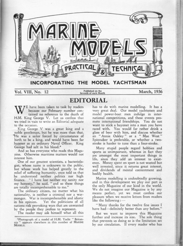
»: £ , Vol. VII, No. 12 Published on the Seventh of each Month March, 1936 EDITORIAL MODELS, Many stupid people regard hobbies and sports as unimportant, whereas in fact they are amongst the most important things in life, since they add an interest to existence. Money spent on sport is not wasted but well invested, since it returns great interest, and dividends of mental contentment and bodily health. Marine modelling is undoubtedly growing, and in this development we play our part as the only Magazine of our kind in the world. We do not imagine our Magazine is by any means perfect, yet we must confess our pleasure when we receive letters from readers like the following : — ‘*Many thanks for the twelve fine issues I have had—definitely better than any before.” But we want to improve this Magazine further and increase its size. The sole thing that prevents us doing so is the limitation set by our circulation. If every reader who has SR ot SE a *Photograph of a model of H.M. Yacht “* Britannia ’’ appears elsewhere in this number of MARINE has to do with marine modelling. It has a very great deal. Our model yachtsmen and model power-boat men indulge in international competitions, and these events promote international friendships. You do not want to stick a bayonet into a man you have raced with. You would far rather drink a glass of beer with him, and discuss whether an “Annie Oakley” or a “ Mae West” Spinnaker is preferable, or whether a twostroke is harder to tune than a four-stroke. gS E have been taken to task by readers because our February number contained no reference to the death of H.M. King George V. Let us confess that we tried in vain to write an Editorial adequate to the occasion. King George V was a great king and a noble gentleman, but he was more than that. “He was a sailor forced by circumstance of birth to be a king, and would have been far happier as an ordinary Naval Officer. King George had salt in his blood.* And so has everyone who reads this Magazine. Otherwise maritime matters would not interest him. One of our greatest scientists, a bacteriologist, whose name is unknown to the public, but whose work has helped greatly to the relief of suffering humanity, once told us that he understood neither politics nor high finance. ‘I have lost neither my sanity nor my honesty,” he said, “and so these things are totally incomprehensible to me.” The ordinary citizen, no matter what his nationality, is neither a criminal nor a warmonger. War is incomprehensible and idiotic in his opinion. Yet the politicians of all nations risk provoking wars that are unwanted by the people they profess to represent. The reader may ask himself what all this
314 MARINE looked at a copy at the club or borrowed one from a friend will buy one for himself, we can safely promise to give readers a better Magazine. With this number we arrive at the end of our Eighth Volume. Time certainly flies! The original staff of MARINE MODELS consisted of four. Of these, unfortunately, two —E. E. Marshall and H. C. Whetstone— have passed away. Mr. A. J. Child has left the staff, and of the original members, only the Editor remains. Yet the spirit of the Magazine lives on, and our present staff are determined to give readers of all sections of marine modellers a Magazine worthy of our great pastime. AN AUSTRALIAN MODELS OUR NEXT PUBLICATION A S we informed readers, it is our intention gradually to put out a complete range of handbooks, covering every subject of interest to the Marine Modeller. This is a big task, particularly as we are determined that each book shall be absolutely the best of its kind. We have now in preparation ‘‘ How To BUILD A MODEL STEAMER,”’ by our esteemed contributor, Mr. J. Vines. This will be an eminently practical manual, and with its aid even the veriest novice should be able to turn out a highly creditable working model. Yet this is not intended solely as a book for the beginner, and even the most expert model builder will find many useful hints therein. Many diagrams are given and several large-scale plans will be included with the book. Price, date of publication, and further details, will be announced in due course. MODEL YACHT CLUB Photo: Leon Cayley, Manley The above photograph shows the members of the New South Wales M.Y.C. at the sailing water, the Dee Why Lagoon, near Sydney, on the Opening Day of the 1935-1936 Season. small edition of the International A-class, with a rating of 28.3in. The club has adopted a This gives a yacht of about 50in. L.O.A., 34in. to 38in. L.W.L., and from 15 1b to 184 1b. displacement, which is found a very handy and portable model. corded. The M.Y.A. Sailing Rules are used. The club is growing fast and all-round improvement is re- We are indebted for the above photo to the Commodore, Mr. R. W. Ross, 24, Cranbrook Avenue, Cremorne, Sydney, N.S.W.
MARINE MODELS HOW TO MAKE MODEL SHIP STEAMER FITTINGS 315 AND ° By A. P. IsARD, A.M.I.Mech.E. (Continued from page 294.) FIG. 127. Sent atesa. : = aed cee To make reamers to suit shafts, take a piece of silver steel rod of exactly the same size as shaft, and carefully file two flats along its length for the length required. These two flats must be at right angles and meet at a sharp edge, also very great care must be used to file to the exact diameter of the rod as otherwise the reamer will be undersized and spoiled. When this has been correctly done, harden and temper by making bright red-hot, and plunge into clean, cold water. Then polish with fine emery to get the bright colour of steel, and re-heat in a clear flame to a straw colour, cooling immediately in clean, cold water. The top of the casing can be made removable for inspection purposes or permanently fixed by soldering. The same applies to the motor casing top, but before this is fixed, insert the pinion shaft, to which the hand wheel has already been attached, and screw oe ment. Se Since the model will be very small it must, of necessity, be a dummy in so far as the electric motor is concerned. However, if the model maker is skilled enough, and so inclined, a tiny electric motor of the permanent magnet kind might be contrived, but it would be necessary to arrange for a very much reduced drive by means of a carefully-made set of gears. In the sketch the writer has arranged the normal electric rheostat control wheel, which is to be seen outside the motor casing, to drive the main winding drum shaft through a simple bevel gear so that by turning this wheel by hand it will rotate the winding drums in either direction. The complication of a clutch and brake gear is hardly a matter that can be usefully incorporated, but dummy levers for this purpose may be added if desired. The whole winch can be made up from odd pieces of brass with the soldering iron. To assemble the main shaft first, fix one of the drums permanently, and slide the shaft through one of the bearings in the casing. Then insert the large gear wheel and continue pushing the shaft through it and the other side bearing. The gear wheel is secured in its correct position with the set screw shown in the sketch. Slip the other winding drum on to the projecting end of the shaft, and adjust the whole until it runs easily and without side shake. Bearings for the main winding shaft and pinion shaft should be little turned brass bushes carefully soldered into the holes already drilled in their respective casings. Whef these are fixed carefully, run reamers of the same size as the shafts through them. The reamers should be long enough to reach through both bearings and so ensure align- — OR the mechanical working of our Welin-Maclachlan Gravity davits, or for other davits, an electrically-driven, totally enclosed winch (as shown in Fig. 127) is quite suitable. This is situated in convenient proximity to the falls on the operating deck, where the man-in-charge has a complete view.
ore tier. cree Se Oe MODELS 5. MARINE SP ARE A ROT NE ST = Seto == 2 Saw yo ES SE,EEC 316 FIG.t28. tightly into the pinion. A spot of solder can be added to the end of the shaft. The pinion shaft should have its end screwed to a size slightly under its diameter so that it forms a shoulder against which the pinion wheel must be screwed tightly. For the gear wheels the local jeweller should be able to find something in his scrap box. Finish the whole fitting in keeping with the class of ship by painting white, grey or black. The control wheel must, of course, be highly polished brass. Fix to the deck by bolts and nuts at the four corners of the sole plate with the nuts on the top side. Wire rope for the winch can be made very easily, as shown in Fig. 128, on a lathe. Select suitable wire—ordinary flower wire produces a very good rope, but is not suitable where there is any real strain, such as mast stays, etc. In the figure three strands are These should be attached to the shown. face-plate of the lathe equally spaced and their ends carried to the back-centre, round The which they must be firmly bound. back-centre must be an easy sliding fit upon the shears of the lathe, so that when the lathe is revolved it may be allowed to follow the tightening wire, or eased up by hand. If the centre distance of the lathe is too short to make a reasonable length of wire rope (bearing in mind that the length of finished wire rope will be only about 75 per cent. of the total length between the lathe centres), fix a nail in a piece of wood and get a friend to hold this at the far end of the room, keeping a slight tension by pulling away from the revolving face-plate to which the wires are anchored. If the model shipbuilder has not a lathe, the same excellent result can be obtained by using the domestic sewing machine’s driving wheel, or any other rotating affair to which the wires can be attached. Quite a number of revolutions are necessary to complete a length, but this and the tension will be found after a few trial runs. A word about ropes and rigging. Ordinary ropes are known as hawser-laid. Several threads of hemp being twisted together make a strand. Three strands twisted together from right to left make a hawser or righthanded rope. A cable-laid rope consists of nine strands, being three ordinary right-handed ropes twisted together from left to right. Cablelaid ropes are coiled from left to right while right-handed rope is coiled from right to left. If a rope is subjected to chafing it is wormed, parcelled and served. Fig. 129 shows these operations: (1) wormed, (2) parcelled, and (3) served. ‘* Worming ” consists of winding spun-yarn between the strands; “ parcelling” is wrapping with tarred strips of canvas, and “ serving” is binding the whole with spun-yarn or other small stuff. The latter is put on against the lay, as in the old sailor’s rnyme— Worm and Parcel with the lay, Turn and Serve the other way. F1G.12.9,
b ‘ by at iS sey F: oH % 3ne {4 ang: mri Ap ing ¥ s a4 es. 22, a. < Pa 23 ORE nae BAG: Ped ~ ese| ae be rt fie > we a >pa = ‘ > Be MODELS Ssud MARINE “ 317 : Py) by 7 \ ese Pe eS y be ‘ k YS 3 oh Ary if “YA r > 5 ay m/ Fy RS 2 wee: ee not be forgotten that extra weight puts the boat down below her marks, and an overloaded vessel is bad in a seaway. Where additional weight is added, it can often be compensated by lightening other parts. If, on the other hand, a boat already lacks stability, it may be a question of either adding ballast or reducing the weight of the top-hamper. In fact, the modeller must give thought to his boat, as naval architecture is, in the main, common sense and experience. The easiest method I know of building a metal hull is that used by Messrs. Tom Curtis & Chew, of the Victoria Model Steamboat Club. In this system the boat is built on a wood former. This, however, is necessary whatever method is employed. As the shape of the boat depends entirely on the former, it is essential to take great pains to get the former fair and true, and this part of the business must not be scamped. If the formeris made solid throughout, a lot of wood will be used, but in this system of building the bottom of the former only is solid and the remainder which forms the boat’s topsides consists of a framework loosely planked up. The bottom of the boat as far as the turn of the bilge is the solid part. This portion can either be carved out of a single thick plank or built up in layers screwed together. The latter method is similar to bread-andbutter building but there is no need to glue the layers together, and screwing suffices. If the builder has to buy his wood this is easier and possibly lends itself to greater accuracy in following the design, but if the builder has a piece of thick board in hand, it is not worth the expense of buying special wood. The bottom must be carefully carved to shape, special attention being paid to getting the two sides exactly alike. When this is ee OME model steamer builders are more at home with metalwork than others. These will naturally give preference to a metal hull. At the same time one sees more badly-shaped metal hulls than wood. This is probably due to the fact that in building a wood hull one carves and glasspapers away until all bumps and ugly angles disappear. Badly-shaped hulls are due to one of two things. Either the builder lacks proper plans, or he is ignorant of the best methods of building a metal hull. I have been asked by certain readers to give instructions for building a metal hull. If the builder has a notion to make a real scale job fully plated up in proper style, my advice is to save that sort of work for a glass-case show model, as it is wasted on a working model, which has to stand hard knocks and rough usage. Even the most careful owner cannot prevent an occasional collision, either with another craft or the sides of the pond. If a full-sized ship gets into collision with another vessel or runs full-tilt against a concrete dockhead, she retires hurt to dry-dock. Yet our models are expected to come through such incidents unscathed. In consequence, for a working model, at all events, hulls have to be proportionately stronger than the full-sized craft and different methods of construction are desirable. Whether hulls are wood or metal, it is highly desirable to keep all weights down as much as possible and make the component parts of the boat as light as is compatible with strength. This applies particularly to tophamper though even below there is no need to make things disproportionately heavy. In adding additional deck details—and in the engineroom, too—the question of stability should never be overlooked, and even if the additional weight is low in the ship, it should — (Continued from page 297.)
moulds. The moulds can be cut out of any wood about 4in. thick, and are secured to the solid bottom by setting them against crosspieces of wood about lin. square. _ It will be seen from the diagram that the boat is built upside down on a building board. The section moulds have to be made sufficiently long to come down to the building board, and a line to represent this should be struck on the plans. Now there is one most important point to remember in connection with setting up the section moulds. Those in the fore part of the boat must have their after faces on the section stations, and those in the after part must have their forward faces on the station lines. The reason for this will be apparent in a minute. positions. | HT ih HH Note how the moulds are set in relation to these. planking need not have carefully-fitted edges, and can be very loose. There must not be big gaps, however, as the plating has to be suppotted all over. Before starting to carve the bottom mark on the top of the wood a centreline and the station lines for the erection of the section when the moulds themselves are screwed to the cross-pieces, they will come in their proper board. act as a bial for the tinplate hull, so the In setting up the section moulds screw the cross-pieces of lin. square wood to the bottom on the far-side of the station line. Then, The diagram shows solid bottom and ends of former, also method of finished, the topsides have to be added. A glance at the sketch which accompanies this article will make the matter absolutely clear. The diagram is not to scale, and is intended merely to show the method of making up the former and laying the keel strakes. In order to make the diagram clear on a small scale certain of the parts have been exaggerated slightly, and the battens forming the planking of topsides omitted. Also it is really desirable to use more transverse section moulds. The solid ends to the former are, of course, recessed to take the ends of the battens which are used to plank up the sides. It should also be added that although certain dimensions are given, these must be varied according to the size of the boat. The builder will have to judge sizes for himself to a certain extent, and also make such minor modifications as are required by the design. The section moulds are erected on the solid bottom and then planked over with thin wood, say, jin. thick. Obviously if the moulds were made full size like the bottom, the planked-up part would be in. full all over. The moulds for the planked part must therefore be reduced by jin. (or whatever the thickness of the planking wood may be) all round to allow for planking. We do not rely on the planking to be watertight (as in the case of a planked wooden hull) but simply to MODELS setting up moulds to plank up topsides of same, but planking is not shown. The broken line represents the sheer. Method of fitting stem, keel and sternpost are shown, also bottom plate. See small diagram (to left) for fitting stem to bottom plate. Section station lines are shown on the building MARINE THE FORMER FOR BUILDING A METAL HULL. 318
MARINE The screws holding the moulds to the building board must be put through from the underside of the building board, and it will facilitate this if similar cross-pieces of lin. square wood are used. When the moulds have been set up, take a batten of the din. wood and offer to the moulds. It will be seen that owing to the curvature of the sides the batten does not take right across the moulds but only on one edge. Rasp the moulds down until the batten takes firmly right across them. It will now be obvious that if the moulds had not been correctly placed with regard to the station lines the hull would not be the correct shape as the moulds would have been too small. It is obviously necessary to put a sort of inner stempiece at the fore end of the former in order to fasten the planking together. As it would be an extremely difficult job to get the planking round the tuck of the counter, this is best carved out of the solid also. These ends of the former are screwed to the building board in their correct positions. Before starting to plank the former, check carefully to see that all is fair and true. Then plank up with strips of din. wood. It will be seen that these have to be wider in the middle than the ends, and also that they have to be cut with a curve that varies with the position of each plank on the boat. In order to avoid distorting the frame, it is advisable to put strips on each side alternately. The builder has not got to get his planks up absolutely tight, as all that is being done is to make a former for the plating. At the same time the way the planking falls is something of a guide for later work. If great difficulty is found in getting the shape of the planks, paper patterns can be cut. If necessary, the planks can be in several lengths. Having finished the planking, rub the former down with medium glasspaper to take out any humps or bumps. This completes the former, and the hull is ready to be plated up. For a medium-sized model X (Single Cross) tinplate is suitable, and for a larger boat XX (Double Cross) tinplate. Thinner plate is inadvisable, as it tends to buckle while being soldered, but the above is thick enough for strength without being unduly heavy. The method really consists of building the hull up in metal strakes, which are soldered together where they overlap. As the largest size sheets usually obtainable are 28in. long, the strips forming the strakes will have to be MODELS 319 in at least two parts. It is inadvisable, however, to have more joins than are absolutely necessary, as these add to the weight of the hull. When the hull is finished, the metal is so thin that it can easily be built up in the painting until the laps of the strakes disappear entirely, leaving a smooth-skinned hull. The first step is to make up the keel, stem and sternpost. The keel for a medium-sized model can be a piece of tin. square brass. The stem is Sin. by jin. brass. The wide way of this is, of course, set fore-and-aft. To bend this, anneal the brass by bringing it to bloodred heat, and allowing to cool. It may be necessary to re-anneal before the bend is complete. The keel has a slot cut in the fore end, to take the foot of the stem, which is riveted and sweated in position. The whole is filed down fair. The stem should be left extra long to permit its being anchored to the former by a strap, as shown in the diagram. The construction of the sternpost and Abracket will depend largely on the design of the vessel. However, this can be made of a piece of tin. square brass like the keel. The sternpost will have to be opened out in order to get the stern-tube through it. This is done by putting a fairly sharp bend in the brass at the required spot and then cutting down the back of the bend with a hacksaw. After the metal has been straightened, a pointed tool, such as a marline spike, can be inserted, and the sides of the cut opened out until it will take the stern-tube. Find a piece of brass rod, about the size of the stern-tube, and insert temporarily in the hole and squeeze the slot together above and below the hole. There will still be little gaps above and below the tube, but these can be filled up when the stern-tube is finally inserted and soldered into lace. The keel and stem can be assembled before being put on to the former, but the beginner will probably find it easier to leave the sternpost until he has got the keel in position on the keel strake. Be sure to get keel, stem and sternpost aligned correctly on the hull. Owing to the sharp bends in the ends, the keel strake must be made in three parts—bow, stern, and middle. This strake goes over the centreline and forms the lowest part of each side, the actual keel being soldered on outside it. At the bow and stern the keel strake laps the stem and sternpost. This will be clear by the diagram showing the forefoot and plating.
320 MARINE Start by bending the middle of the keel strake over the former. Cut and bend the forward part, leaving the fore end open to take the stem. Solder these together. Then make and solder on the stern part. There may be a little difficulty in bending the end parts of the plate, but it will be found that the tinplate can easily be worked down into shape by means of a piece of wood. Drop the keel and stem into place, and solder to the plates. The sternpost is then fitted. The lower end of this should be pinned before being soldered to the keel and its upper end can be screwed temporarily to the wooden after end of the former. The plates lap this in the same way as they do the stem. The next strake has probably to be made in two parts. As the girth of the boat is greatest in the middle the strips of tinplate for the strakes will have to be widest in the middle. How wide the builder can make his strips will depend on the shape and size of the boat, but he should get them as wide as he conveniently can in order to save work. Cut a brown paper pattern first to get the shape, and use it to make a pair of strakes, When the one for each side of the boat. strakes are fitted they can be soldered into position. Fit the after part of each strake first, so that the fore part laps it. The strakes overlap about }in. or slightly more. One point that must be very carefully watched is that the strakes must lie flush on the former and do not spring away, as any error in this respect is intensified with the next strake. It will help the builder to get his plates down flush while soldering if he has a strip of thin wood, say, 6in. long, and holds this on the plate parallel with the overlap he is working on. The remaining strakes are put on in the same manner. There are one or two little points that will help the builder in his work. In order to hold the plates in position until they are soldered, the worker can wind a cord round the boat, using wedges where there is a hollow. An alternative method is to use tintacks, which are driven in just far enough The to hold and subsequently withdrawn. holes for the tacks must be started with the point of an old scriber, or something of the kind. When the boat is finished these holes have to be filled with solder. The main disadvantage of using tacks is that it leaves little burrs on the inside of the hull. It is useless MODELS to try to hammer these out as it will spoil the hull, and they have to be filed off sufficiently to prevent the danger of scratching the hands when handling the boat. As the builder approaches the sheer, he should watch the shape of the strakes so as to get the top strake a nice, wide one, with its upper edge shaped to the sheer. _ When the boat is plated up, take the building board off and take the moulds out. If there is any part holding, the moulds must be persuaded out. The bottom of the former should then come out without any difficulty. At this stage a metal hull is very flimsy. The best thing to stiffen the boat up is to fit a wooden shelf. This is a wood batten, say, 4in. wide by Zin. deep. The battens are held in place with little brass nails, spaced every 2in. or 3in., and clenched inside by having the points turned over. The points, by the way, should not be turned with the grain of the wood. The back of the batten, where it goes against the hull, should be well luted with a mixture of white lead and varnish, and put on wet. The heads are well pressed in, and soldered over, and, once the boat is painted, become invisible. In order to support the deck, beams have to be fitted. These are wood, cut straight on ~ the under-side, and curved on top according to the camber of the deck. The ends of the deck-beams are mortised into the shelf. The width of the boat should be carefully checked on each deck-beam, so as to be sure the hull has not sprung at all. The deck holds the whole fabric of the boat together, and once it is on, the hull will become strong and rigid. If an aluminium deck is being used, it can be screwed to the shelf and deck-beams. If a tin deck is being used, this can be soldered to the top of the side, in the usual way. If an aluminium deck is used, it is advisable to protect the under-side with either paint or varnish. At the sides, where it beds on the shelf, and where it beds on the beams, these should be well luted with the white lead and varnish mixture. One point about the soldered tin deck is, that it must be regarded as permanent, and, once on, cannot be taken off again. I omitted to mention the great advantage of using a wooden shelf. In a metal hull, this not only adds rigidity, but also gives a certain amount of elasticity that enables a_ hull built this way to take a blow without denting.
= MODELS 321 er SHIPS’ BOATS By G. W. Munro (Concluded from page 302.) HE rather pretty little yawl which I am she using to illustrate the concluding notes on old-time ships’ boats is taken from Steel’s Draughts of 1804. The drawing represents a yawl of 26ft. length overall, not including the rudder. The lines are not built up on one basic arc and a number of tangents, but it will be seen that most of the sections are a combination of two converging arcs and tangents. However, the design is still a very simple one and very easy to fair up. Personally, | think that this boat is one of the best looking I have illustrated in these notes. The moulded breadth is 6ft. 8in., and the depth amidships is 2ft. 1lin., 3ft. 6in. at the stem, and 3ft. 9in. at the stern. The keel is 33in., sided below the rabbet. The stem is 34in., sided before the rabbet at the head, and I4in. the rabbet. The transom is 3ft. 8in. broad, or moulded at the top, and lin. thick or sided. The knees were made of iron on these yawls, as they were on barges and pinnaces. The sternpost is 23in., sided at the tuck, and 24in. at the keel. The sternpost is 8in. broad at the keel and 2in. at the head, including the transom. The floor timbers are lin. sided, 13in. moulded at the head, and 34in. moulded at the throat. The futtocks are I4in. sided at the heels, and I4in. at the heads. All the timbers are Il4in. moulded, and the scarf is lft. 10in. in length along the timbers. The keelson is 10in. broad and 1 4in. thick. The footwaling 3in. thick. There are five thwarts. The main thwarts are 10in. broad and 13in. thick. The afterthwarts are 74in. broad and I4in. thick. The fore-thwarts are 74in. broad and 14in. thick. Loose thwarts are the same size as the foreand after-thwarts. The knees are all of iron, as mentioned above. The benches are 1lin. broad and I4in. thick. The deadwood is 24in. sided. . The bottom planking is jin. thick, and the landing strakes are 8in. broad, the upper strakes 8in. and the gunnel 24in. deep by 2in. thick. The breasthook is 2in. sided, 2ft. 4in. long. It is 34in. thick at the throat. As will be seen from the drawing, there are washboards at the bow and at the stern, but nothing in the middle or waist. The bow washboards are 44in. high, and the stern washboards are 5+in. The rudder is Ift. 5in. broad at the heel, lft. O4in. at the lance, and 7in. at the head. It is gin. thick throughout. The scantlings I have just given are for a yawl 26ft. long. There was also another and smaller yawl in the Navy. It was only 16ft. long with a beam of 5ft. 6in. and a depth of 2ft. 34in. as the main dimensions. The rest of the scantlings are proportionally smaller. Naturally, the thwarts are not reduced in the same proportion, but are as follows: The main is 9in. broad and 13in. thick; the others are 7in. broad and 14in. thick. The benches are also lin. less in width and are only 1 din. thick. The interior arrangement of the 26ft. boat is exactly similar to that of the pinnace which was shown on page 242 of the December, 1935, number. If possible, it is perhaps a little more showy, with the mouldings on the washboards, etc. Altogether, 11 different boats have been described and illustrated since the beginning of Vol. VIII, and it should now be possible for the modeller to adapt these lines to his individual requirements and fit out his ship with boats completely. The period taken was not a long one, but in the sixty-five years covered the development can be very plainly seen. All that is necessary is the length, depth and breadth, and it is a simple matter to design a typical boat for this period by using one or other of these designs as a guide. In the next Volume I hope to take a later period and work up to the boats carried on the last of the big square-riggers, which are rapidly decreasing in numbers each year. ee = we hntie MARINE THE END.
VIMVAHOuUMeIG—p08TAq*D MOUNIA 322 MARINE MODELS
MARINE MODELS 323 A CARDIGAN BAY SCHOONER—1865 By G. W. Munro (Concluded from page 221.) INCE the previous article on this little S schooner was published in our Novem- ber number I have been fortunate enough to find the entry in Lloyd’s Register, and so am able to give the final figures according to that authority. Apparently, she was slightly altered in her dimensions, but not enough to make a very serious difference. Her name also appears and gives added interest to the design. She was the ** Lizzy Ellen,” owned and sailed by D. Davies. She was put into commission in 1866. Her registered tonnage is 73; length between perpendiculars 72.7ft.; beam, outside planking, 20.2ft.; depth, moulded, 9.8ft. She was classified as for 12 years Al at Lloyd’s. The first voyage was from Cardigan Bay to the Mediterranean Sea. Her L.W.L. worked out from the above figures was 69ft. 9in. Now for a few figures on her scantlings. The timber and spacing for a ship under 100 tons reads 19in. Floors, sided and moulded at keelson, if squared, 74in. Double floors, sided and moulded at keelson, if squared, 64in. First futtocks, sided and moulded at floorheads, 64in. Second futtocks, 6in. Third futtocks, or long top timbers, 6in. Breasthooks, wing transom, etc., 84in. Keel, stem, apron and sternpost, sided and moulded, Qin. Keelson, also main piece of rudder from lower part of counter upwards, sided and moulded, 10in. Wales, 34in. Bottom planks, from keel to wales, 24in. Sheer strakes, topsides, deck clamp, 24in. Waterways, 4in. for hardwood, and 44in. for fir. Plank-sheer, 24in. Flat of deck, 24in. The plate showing the sail plan and general arrangement of the deck is to the scale of jin. =Ift., and I have corrected the length between perpendiculars on this drawing to agree with the official measurements in Lloyd’s Register. The bulwarks are the usual height of 3ft. 6in. from the top surface of the deck to the top of the rail. The wheel box is easily spotted, just over the rudder-head, and, like many other details on the vessel, it needs no explanation. The glazed box just in front of the wheel is the binnacle containing the compass. This type was usual in the middle of last century, and it can be taken for granted that the compass will have the needle balanced on a pin, such as we see in toy compasses. The two thin uprights, between the compass and companion, are bollards or bitts. They are the continuation of frames 18 and 19. The companion has the usual sliding roof and double doors, a ship’s fitting that does not seem to have changed for many years, and is still seen to-day on many ships. Just forward of the companion is the “Charlie Noble,” or cabin stove funnel. Forward of this again is a small skylight, with hinged lights on top to act as a cabin ventilator. The pump is 5ft. aft of the centre of the mainmast, and is of very simple pattern, similar to those seen in country districts all over the world. The mainmast has a spider band at about 2ft. 6in. above the deck. The diameter of the mast should be 3in. to every yard in length. The length is taken from the top of the keelson to the cap of the lower mast head. Forward of the mainmast is a dolly winch, which seems to be peculiar to schooners, and not found on other craft. To look at, it resembles a mangle more than anything else, with its framework and gears. It is not unusual to have the top of the dolly winch shaped into a horse for the foresail sheet, but in this case the horse is bolted to the deck, just forward of the winch. The main hatchway is situated between frames | and A, or one frame space beyond the midship section each way. It is impossible to say just how wide the hatch is, but it may be taken for granted that its sides will be in line with the edge of the other deck fittings. However, it would not be very far out to make them in the proportion of 6 : 10. The foremast has a fiferail round it, with the usual belaying pins at each side. The forehatch is placed between frames F and J. (On the drawing the latter was shown as G in error, as there are two frames not drawn in.) The forehatch will be more or less square to fall in line with the main hatch. The fo’c’sle companionway does not appear to have a sliding roof, but merely the double doors. The fo’c’sle stove is just below the companion, and the funnel, or Charlie Noble, can be seen (Concluded on page 326.)
326 MARINE MODELS PETROL ENGINE and HYDROPLANE TOPICS By J. B. INNOCENT (Continued from page 300.) HE workshop bench should be as rigid and heavy as possible, and should pre- ferably be used for bench-work only, Certainly the lathe is best on a stand or small bench of its own, for if it is mounted on the main bench the swarfe persists in mixing itself up with everything it should not. The vyce should be of ample size, with inserted steel jaws, and must be firmly bolted down to the main timbers of the bench. Small tools should be kept in racks and not left on the bench. This rack may be very simple, and french nails will be found useful in this respect. Drawers for the storage of tools usually result in the tools getting hopelessly mixed up, but they have the great advantage of minimising the rust evil. If drawers are fitted, they should be shallow so that each only holds one layer of tools, and they can be further improved by the provision of partitions, so that each tool or type of tool may have its own home. The size of the bench is usually decided by the space available, but it is difficult to have too much bench space. Hand tools should, as a whole, be bought as required, and not in sets. Of course, a start must be made, but do not be too anxious to and not as a place for general storage. The start of the file range should include one big, rough one, preferably flat, to use when any quantity of metal has to be moved, and one superfine flat, or three square, i.e., triangular, oh use in finishing shafts in the lathe. In this connection many people are ready to proclaim from the skies that no respectable workman uses anything but a lathe tool in the lathe. Well, it may be so, but I have still to meet the lathe and operator capable of finishing a shaft to the correct interference fit in a ball-race straight off the tool, or to get the finish and accuracy possible by the judicious application of fine emery cloth. i am well aware of the fact that a spring tool can produce a mirror finish on mild steel, but a spring tool does not turn round, and mild steel is scarcely the ideal shaft material for a high duty engine. One hammer, weighing about eight ounces, will do to begin with, and should be of the ‘* engineer’s ” type, with a ball back pein for riveting. It won’t be much good for forging, but to try to use a heavier one on such jobs as fine chipping is about as hopeless. Even- tually a nelection from two ounces up will be complete a range, as it is often possible to find what you need at clearance prices and if these opportunities are carefully used, the eventual equipment of the shop will benefit, but do not buy things just because they are cheap, or you may have to go without something you really acquired, say, half a dozen, with the heaviest weighing about four pounds. Even if a drilling machine is installed, a hand drill will be required; it should be of the two-speed type, taking drills up to 3in. Drills themselves should be of the twist variety for general work, though straight flute drills are referable for drilling brass. To buy all sizes, need. fae No. 80 up to 4in., is quite out of the A CARDIGAN BAY SCHOONER—1865 (Concluded from page 323.) them both. Usually the bowsprit is stepped into this post by means of a small slot. projecting above it. Personally, | rather fancy that it is placed on the port side of the companionway, and comes up through the deck on that side about 10in. or 12in. away from the side of the companionway. The windlass is placed just forward of the companion. The actual details of this fitting are rather hard to distinguish, but we can suppose that it was typical of its kind. The bowsprit is fidded into a sampson post. In the drawing this is shown as passing right through the post with a fid driven through The sail plan is very normal in its way, but I notice that the foresail is rather narrow at the head. Usually, the foresail has its leech more or less parallel with the fore-side of the mainmast. It is difficult to say just how much of the rigging would be chain, but the reader will get a very good idea of the practice at this period by consulting Kipping’s little book on Masting and Rigging. The sail plan explains itself and needs no further mention here, as it has been dealt with so many times in these pages.
MARINE question for most people, for there are 139 different sizes in the number, letter and inchsize ranges. Reamers are very useful, particularly the “ Quick Set” type of adjustable ones, but run away with money if bought needlessly, for they are expensive things, if of good quality, and usually of little use if cheap. One or more pairs of tool maker’s clamps are very useful, particularly when cutting out sheet metal, as two or more pieces can be held together and operated on at once. The normal type of tap and die holders should be supplemented by a tail stock dieholder, for the accurate screwing of rod in the lathe. Two types are available. One fits in the tail stock by a taper back end, is all in one piece, and is not fitted with handles; the other is in two parts, one being taper at the back end to fit the tail stock, but the dieholder itself is free and slides on, and is guided by, a spindle formed on the front end of the tapered part; handles are fitted to this type. The second is the better of the two, and, particularly so, for very fine threads. If a tail stock holder is not available, a good thread can still be obtained by supporting the die and holding it true with the jaws of the drill chuck, so that they press on the back face or by the similar use of a morse taper adapter, if the tail stock is bored No. 2. When working this wangle, the die is held in the ordinary type of holder with the full diameter hole at the back. There is one matter I must stress, and that is, that twist drills do not produce accurate holes either in size or direction, and when an accurate hole is required it should be finished to size by boring or by opening up a pilot hole with a D bit if it is too small to bore out. In going through some of my back notes, I find I have never referred to an engine really suitable for a beginner’s effort. I also find that most beginners are a bit chary of trying to make a four-stroke racing engine as their first attempt. I have therefore been keeping my eyes open for a design that is reasonably simple to build, and which can be reckoned on to put up a performance that will make it worth while. Naturally, I have looked for a two-stroke of the overhung crank type, and have now found one that is as easy to build as a motor very well could be. The MODELS 327 performance to be expected is certainly not phenomenal, but the motor should make ample power for a straight runner in its standard form. As designed, the ports are small but sufficient for its intended purpose, and there is sufficient metal round the ports to permit of enlarging them should the builder so desire. This engine, which is of slightly over 15 c.c. capacity, is the one marketed by Mr. Lowry, of 6, Grasmere Gardens, Ilford. In designing it he has paid much attention to easy machining, so that the motor offers the minimum of difficulty to the beginner, and the castings could be turned up by an experienced model engineer in a week of evenings. Ease of building has resulted in a banjo-type crankcase, that is the cylinder jacket and crankcase are in one, and a cover is used on each side of the crankcase, one of these carries the main bearings and the other is plain. A shrunk-in iron liner is used in the aluminium cylinder jacket, and this is the only difficult part of the machining, but then you can’t get it all ways. The crank, with its overhung pin, can be made from bits or cut from the solid, but as it can be got out of a piece of Ford tonner side shaft in one piece, this should be done if the shaft is available. I admit that the lined aluminium cylinder is something I have already advised you not to use in a racing job, but it is quite capable of dealing with the heat from an engine of this type. It is my intention to devote my next few articles to the machining of engines, and | think I can do no better than run through the machining of this motor which will represent the minimum amount of trouble that should be taken. Then I will contrast this with the building of a pukka four-stroke engine containing as many difficulties as I can think of. In doing this I shall suggest one or two modifications in the two-stroke—one to bring it within the 15 cc. standard, and another to correct a fault in the dimensions of the piston. A set of carburettor castings is also obtainable from the same source, and these, like the engine, are simple and practical, both to build and operate. At the same time there is the metal in the castings to make a full diffuser jet carburettor with a proper venturi choke similar to “ Betty’s,” but reduced for the 15 c.c. capacity engine.
328 MARINE OBITUARY MODELS Annual General Meeting of the M.Y.A. last January. Many men would have given in, but Mr. Littlejohn’s strong sense of duty kept him going, and he carried on his work for the Association until a few weeks ago. His illness then developed alarmingly, and he was obliged to enter Hammersmith Hospital, where he died on February 28. Mr. Littlejohn was a born official, being extremely accurate and orderly. He was an outspoken man, with a: hatred of cant and dishonesty of any kind. He had many friends and was respected by all who knew him. His club, the M.Y.A., and the sport in general will feel his loss greatly. He leaves a widow, and to her, and to his son, Mr. A. W. Littlejohn, we offer our sincere sympathy in this bereavement. The photograph Steinberger. MODEL reproduced is by Mr. O. YACHTING ASSOCIATION The late Mr. A. Littlejohn I’ is with the greatest regret that we announce the death of Mr. A. Littlejohn, Hon. Secretary of the Model Yachting Association, and Commodore of the Model Yacht Sailing Association of Kensington. Mr. Littlejohn was one of the now rapidly diminishing band of pre-War model yachtsmen, to whom the present generation owe so much. He was one of the earliest members of the M.Y.S.A., and the present position of the Kensington club is largely due to his efforts. For many years he has been its Commodore, and under his wise guidance it has become one of the strongest clubs in the country. When the Model Yachting Association was founded in 1911, Mr. Littlejohn took a hand in its organisation, and when the national association was reorganised and restarted in 1923, he was again to the fore, and was elected its first Vice-Chairman. When the Association instituted the registration of model yachts, he became its Yacht Registrar. On the retirement of Mr. C. N. Forge from the office of Hon. Secretary, in January, 1934, Mr. Littlejohn was elected, and filled this position until his death. Mr. Littlejohn was in the printing trade, and a prominent member of the Printing Trades Union. His retirement from business coincided with his election to the Secretaryship of the M.Y.A., and since then he has devoted his entire time to the organisation of the sport. Although he handled a model yacht well, Mr. Littlejohn did not compete in many open events, In his position as Commodore of his club, he preferred to put others forward, particularly promising younger members, whom he was always ready to help and advise. The illness, which led to his death, commenced some months ago, and he was far from well at the WING to the sad illness and death of the Hon. Secretary, Mr. A. Littlejohn, the Emergency Committee has made the undernoted arrangements for the work of the Association to be carried on until a new Hon. Secretary can be appointed. Club Secretaries and others are particularly requested to assist by addressing all corre- eae to the gentlemen whose names are given elow. Any Club or Individual Member that has not already paid the Annual Subscription, is requested to send same as soon as possible to the Hon. Treasurer, Mr. J. E. Cooper, 26, Warren Road, Wanstead, Essex. Club Secretaries are requested to note that all applications for Registered Numbers must (in accordance with the new Rules) be accompanied by the yacht’s completed Rating Certificate duly signed. All applications for registration must be sent to the Temporary Registrar, Mr. W. H. Bauer, 10, Celbridge Mews, Porchester Road, London, W.2. All Entries for Races held under the auspices of the M.Y.A. must be accompanied by the necessary Entrance Fees and sent before the prescribed closing date for entries to the Temporary Racing Secretary, Mr. O. Steinberger, 142, Queen’s Road, Peckham, London, S.E.15. All applications for Rule Books, Certificates and Score Cards published by the Association must be sent, accompanied by remittance to cover, to Mr. A. W. Littlejohn, 19, St. Dunstan’s Avenue, Acton, London, W.3. Until further notice, all other correspondence should be sent to the Acting Hon. Secretary, Mr. W. J. E. Pike, 248, Burrage Road, Plumstead, London, S.E.18. Under the circumstances delay has occurred in printing the new Sailing Rules, but these are in hand, and should be available shortly, when notification will be given, and price announced. C. N. FORGE, Chairman, M.Y.A.
MARINE ae: BeOS ee il ————= gt aK ek eR DERBY —~ — — = MODELS is oF er ———= a a. 9—— oo nde ry F ti ——_ oo? — | 2 Ss as —— me <7: @ ake. 0 ——6 0 The officers who officiated during the last season M.Y.C. The Club’s 13th Annual General Meeting was held on February 14, under the presidency of Mr. T. Spendlove. The Hon. Secretary presented his report and reference was made to the great loss the Club had suffered by the death of Mr. T. H. Ratcliffe, who _ was fatally injured in a motor crash last year. The statement of accounts showed a very satisfactory balance. The following prizes were presented to the prizewinners by Mr. W. H. Allen: Club Cup, Preston Jones Cup, Ling Cup, Handicap Race, Ron Limbert; Jenkyn’s Trophy, Mr. Harrison; Consolation Cup, Mr. Hunt. Ron Limbert is one of the younger members of the Club, and we extend our hearty congratulations to him on creating a record by winning four prizes. W.H.A were enthusiastically re-elected for 1936, namely :— President, Mr. W. Bliss; Vice-Presidents, Messrs. J. E. Cooper, H. Hood, A. J. Hugo and G. A. Piper; Commodore, Mr. H. G. Howard; Vice-Commodore, Mr. A. Littlejohn; Treasurer, Mr. O. Steinberger; Secretary, Mr. A. J. Ford, 8, Forest View Road, Loughton, Essex. The meeting terminated with a cordial vote of thanks to the Chairman. A. J. F. ; NORFOLK AND NORWICH M.Y.C. The Club held its Annual General Meeting on January 18 at the Y.M.C.A., Norwich. The President, Sir Henry N. Hoimes, presided. The Hon. Secretary, Mr. W. J. Meek, Jnr., read a report on last season’s activities. The Hon. Treasurer, Mr. affiliated clubs with the President, Mr. W. Bliss, in the chair. The Honorary Secretary gave his report on the past season’s activities. One of the most pleasing features of the evening was the affiliation of the South-Western Model Yacht Club in the League, which, together with the Model Yacht Sailing Association, of Kensington, Highgate, Clapham, and Forest Gate Model Yacht Clubs, brings the total to five clubs in the League. The sailing water of the South-Western Model Yacht Club is at Clapham. The contests during 1935 for the Stanton Cup had resulted in a victory for the Model Yacht Sailing Association with a total score of 151 points. Highgate Model Yacht Club was second with 127 points, Clapham Model Yacht Club 80 points, and Forest Gate 74 points. The League Championship Cup, sailed for at the Round Pond, September 14, was won by Mr. G. W. Reason of the Clapham Model Yacht Club, who was also the winner of the President’s Medal. Fixtures for 1936 were arranged as follows : — “* Stanton ’’ Cup Events— Ist Round, at Highgate, March 21. 2nd Round, at Round Pond, Kensington, May 2. 3rd Round, at Forest Gate, June 27. 4th Round, at Clapham (South-Western M.Y.C.), September 5. 5th Round, at Clapham (Clapham M.Y.C.), September 12. * League Championship ’’ Cup—to.be sailed for at Clapham, September 19. Treasurer, Mr. A. M. Blake; Rear-Commodore, Mr. W. J. Meek, Snr.; Hon. Secretary, Mr. W. J. Meek, Jnr.; Committee, Messrs. H. K. Finch, H. Eglinton, E. Hill, and W. Mayhew. The Committee decided that Class Racing should be restricted to two Saturdays per month, and the other Saturdays devoted to handicap and other racing, in which boats of any type could compete. MODEL SAILING CRAFT By W.J. DANIELS and H. B. TUCKER. Profusely Illustrated with 7 Complete Designs, 163 Diagrams and numerous Photographs. Price 25/-, postage 9d. The Best Textbook for Model Yachtsmen. ORDER YOUR COPY FROM: Marine Models Publications, Ltd., 52, Fetter Lane, London, E.C.4 _ The Annual General Meeting of the above was held on January 19, at the Woolpack, Moorfields, E.C. The meeting was fully representative of all the A. M. Blake, presented the accounts showing a credit balance of £9 7s. 6d. Mrs. H. K. Finch then presented prizes as follows: Dakin Bowl (A-class), ‘* Kingfisher,’’ Mr. G. M. Smith; Gamage Cup (10-rater), ‘* Diana,’’ Mr. H. K. Finch; 2nd Prize (10-rater), ‘* Rhoda,’’ Mr. G. Self; Wheeler Cup (52in. O.A.), ‘* Vale,’’ Mr. A. M. Blake; 2nd Prize (52in. O.A.), ‘* Valediction,"” Mr. A. M. Blake; Commodore’s Cup (36in.), *‘ St. Tudno,’’ Mr. J. Harston; 2nd Prize (36in.), *‘ St. Seroil ’’; Wale Trophy for Best Junior Skipper of Year, Mr. E. Hatch; Hill Cup for Steering, Mr. J. Harston. The following officers were elected: President, Sir Henry N. Holmes; Commodore and Hon. ————E LONDON MODEL YACHT LEAGUE
** The King’s life has passed peacefully to its close.’’ The voyage 1s ended, haven reached, Our sailor King gives up the helm, While hovering Angels sweetly chant A requiem. May we, who wait another tide, In depth of sorrow, yet with pride In him who pointed out the way; Sheet home our canvas truer yet Till we, too, reach the shove. HE report from Queen’s Park for last season T is exceedingly encouraging and all the por- tents point to a continuance of the renewed enthusiasm that has characterised this Club recently. It has had a more successful season than for some years past. Representatives have attended open events to a much greater extent than formerly, and the home waters have produced 10 prize races and 18 Club contests, with a good average of entries, comprising both 12-metre and 6-metre classes. The Club Trophy for the 12-metre was won by ‘‘Alwyn”’ —true to name—{J. Miller), with the hardy old ** Ardnamurchan *’ (Capt. J. S. McDonald) close in her wake. The 6-metre trophy went to ** Aros ”’ (Murdoch McMillan), with ‘‘ Mohawk ’’ (R. Thomson) as runner-up. A new special social committee has been set up and it has already justified its exist- ence by promoting three very successful gatherings at which lectures on topics appealing to model yachtsmen have been given by some of the memThe Club has set a seal on the season’s bers. activities by putting forward an application for affiliation to the M.Y.A., and goes forward to the future with anticipations of functioning in a wider Good luck to sphere and increasing prosperity. them. Merrily defying all the rigours of the severe weather, the Kirkwall Club quietly and uncon- cernedly proceeds with its racing season. A casual remark, ** We have been troubled with frost and snow,”’ appears almost as if by accident. We should think so. A regatta occupying three sessions, two preliminary races and a final, for 5-raters, with the ‘* Meil *’ Cup as an incentive, has been successfully carried through during January. The first race was subject to disagreeable conditions with a strong Northerly wind necessitating storm canvas, and, when Kirkwall calls a wind ‘‘ strong ’’ it means strong and no mistake about it. The course was set for a close reach and run, and at the close of the proceedings the three leading scores were returned by ‘* Dragon ’’ (D. Wooldrage), 10 points; (T. Wilson), 9, and ** Vala’ (M. Allan), ‘* Vega 8. The second race again encountered a strong, but Southerly, wind, and third suits were bent. Leading craft in this section comprised ** Thistle ”’ (T. Dearness), 9 points; ‘* White Coo ”’ (J. Harrold), 9, and ** Spray "’ (A. M. Morgan), 8. The final, consisting of the above three boats in each section, took place under easier conditions, allowing a full spread of canvas in a light Southerly breeze, with again a close reach and run. The final placings were: ‘* Dragon,’’ which finished with a total of 19 points out of a possible 20, and took premier honour for the second year in succession; ‘** White Coo,’’ a good second with 17 points. ‘‘ Vega ”’ and ‘* Spray ’’ ran to a dead heat with 164 points for third place. The consequent final went in favour of ‘*‘ Spray ’’ by seconds, and provided an exciting termination of the event. Our friends have favoured us with a Calendar for 1936, consisting of a rather attractive photograph of their fleet at the starting station, which we much appreciate. Our remarks regarding the ‘‘A’’ and other classes in our last issue have brought us quite un- expected expressions of approval, from which we infer that we have gauged the feelings of our constituents even more correctly than we had imagined. We do not want it to go forth that we are antagonistic to the International Class, however. We are only concerned with presenting as accurate an impression as is humanly possible of the trend of in interested those among opinion general the sport in Scotland, irrespective of our own per- sonal ideas, although we will not be backward in giving them also when it appears to be opportune or desirable. We at least try to give consideration to the ‘‘ other fellow’s ’’ standpoint, and are sometimes constrained to agree he is right, in the light of cold reason and without rancour. Meantime ‘‘ America Calling,’’ which new feature we welcome with much interest, in the February issue curiously enough brings strong confirmation of our own remarks. We hope America will continue to call, free of atmospherics, and give us all a clear understanding of the tendencies in force among our transatiantic colleagues. The next item on the programme (Beg pardon, Mr. Editor, we are going ali radio), is to chronicle the fact that we by no means had all the advices as to new constructional activities. Since our last effusion we are informed that the West of Scotland _Club have other two or three A-class boats under way in addition to the one already standing waiting the disappearance of ice from the pond to obtain trimming tests. We are also given to understand that the Club has expectations of a new Cup, to be provided for the benefit of the International class. We are pleased to record also that G. F. Paisley, Esq., has kindly consented to become Hon. Com- modore of the ‘* West,’’ and we appreciate his advent and interest in our sport. Persistent rumours reach us of the possibility of an Eastertide visit to Scotland by some of our friends from Wales, together with all sorts of delighted hopes that it will materialise. With these we align
MARINE MODELS 331 ourselves and trust the event will cement the good fellowship evident on every side. Just such con- tacts are worth reams of written sentiments. _At the moment of writing the climatic condi- tions point to anything but model yachting, and all our waters are icebound. As there are a number of new productions ready for launching, this is regarded with no little impatience in certain quarters. However, we must not be selfish and, after all, it is wonderful how quickly the time passes, all too quickly as the years go by for some of us, and we will soon be in the full flood of active racing again. Meantime we gaze upon the graceful evolutions of the skaters and wonder how we would fare if we essayed to try this sport, in which we once delighted? We are afraid we were somewhat more supple and lithe in those far-away days, alas! Our Navigating Officer says, ** No, little boats are about your mark now! "’ And the prophet was always without honour in his own country. May we extend congratulations to our old friend, Mr. G. W. Munro, on his accession to the Council of the M.Y.A. once more. We know what a hard and enthusiastic worker he is, and have no doubt his presence on the board will be of value. THE SCOTTISH COMMODORE. MODEL YACHT CLUB BURGEES HE following letter has been received from Mr. C. O. Brook, Corresponding Secretary, Deeper Hudson M.Y.C., 912, Broadway, Rensselaer, New York, U.S.A. :— ** For several years I have been collecting the various flags of American Model Yacht Clubs. I made a panel of mahogany, on which I carved and painted all the flags I was able to obtain. ‘**I am extremely anxious to obtain the flags of every club throughout the World, and wonder if you would mind mentioning it in the pages of MarRiNE MODELS, so that club members who read your valued Magazine may see it, and will perhaps be so generous as to send me a simple pencil sketch with notation of colour arrangements, etc. ** If I can secure these copies, I will make another panel for each country, so that when our clubhouse is erected we can display them in a place of honour. ‘* | might suggest that all clubs have such a panel, not alone for its decorative effect, but because | believe it would be interesting to every model yachtsman to be familiar with the various flags flown by clubs throughout the world.” May we ask readers to co-operate with Mr. Brook and send him the copies of burgees he requires. If he gets all the flags of British M.Y. clubs alone he will have plenty to do. Another a View of 10-RATER ‘‘ WEETAMOO ”’ ANOTHER M.M. MODEL Dear Sir,—Enclosed photos are of my model yacht ‘* Weetamoo.’’ She was built from the ‘ Stella ’’ 10-rater sharpie design, which appeared in MARINE MODELS. In her trials she has shown a very fine turn of speed, and she has proved a very reliable and steady boat. Her builder is my father, Mr. A. E. Crespin, of the Southampton Model Yacht Club, and, whenever she is at the lakeside or on the water, she gains the admiration of everyone. Please accept my sincere thanks for such a splendid design, and my heartiest congratulations to Mr. W. J. Daniels, for a fine piece of work. Yours sincerely, A. J. CRESPIN, Hon. Secretary, Southampton Model Yacht Club. 55, Clifton Road, Shirley, Southampton. from MARINE MODELS. a ae er ‘‘ STELLA ’’ DESIGN.
332 MARINE MODELS MODEL YACHTING IN GERMANY Dear Sir,—Interested in the proposal by the Kopenhagen ‘‘ Model-Sejlkiub ’’ in January MARINE MobELs, I also beg to submit a report concerning Model Sailing in Hamburg, Germany, which I hope you will likewise publish, and which should help to improve international co-operation among Model Sailing Clubs. With sporting greetings, Yours very truly, H. F. WARK, Modellabteilung, Segler Vereinigung Niederelbe, Hamburg 4, Hafenstr. 124. MODEL SAILING IN HAMBURG, GERMANY Two years ago, when the German Sailing Association (Deutscher Seglerverband, Berlin) started to reorganise Model-Sailing:in Germany which, after the World War, had been entirely neglected, Hamburg Sporting Circles specially were deeply interested in this development. In Hamburg Model-Sailing in pre-War times had been in prosperous shape, but all the various ModelSailing Clubs of this city had to be dissolved after the War, with the exception of the ‘* Model-Sailing Club of Oevelgoenne of 1888.’’ In 1934 this Club was joined to the ‘‘ Segler Vereinigung AltonaOevelgoenne.’’ It had,a handsome fleet of models of many different kinds and sizes. All these boats, however, did not comply to the specifications and ratings of the new model classes created by the German Sailing Association. The chief ambition of all concerned, therefore, was the building of new, modern models, and the result was that the ‘* Segler Vereinigung Niederelbe,’’ of Hamburg, under the leadership of its member, Mr. Wark, added a new division to its club for Model-Sailing. This Model Club started construction of 15 little 48in. model yachts, designed by a skilled naval architect and complying to the new specifications of the German Sailing Association’s 1/2 Square-metre Modelsharpie Class. These 15 models were built during the winter of 1934-35 by 15 junior members of the two Hamburg Yachting Clubs: ‘* Segler Vereinigung Niederelbe,’’ and ** Segler Vereinigung Altona-Oevelgoenne.’’ In April, 1935, these new models were completed and shown at a big Modelboat Exhibition held in Altona. The boats created much interest, and were greatly admired. At the same time another Hamburg Yachting Club, located in Blankenese, near Hamburg, took up Model-Sailing and formed a Model-Sailing Club, this being the third in the city. They designed and built a number of new models, also complying to the new regulations of the German Sailing Association, and selected the smallest type model specified (Deutsche Jugend Klasse). Their models had a first regatta on the Elbe in the summer of 1935. The 1/2 Square-metre Sharpie Models of the other two clubs had their first try-out on the Alster Lake, made At sions in Hamburg, where 19 of these new boats ; their appearance in October, 1935. the moment four Model-Sailing Clubs, diviof the following Hamburg Yachting Clubs, exist in this city :— Segler Vereinigung Niederelbe, Hamburg (H. F. Wark), “ae Vereinigung Altona-Oevelgoenne (W. Siemsen), ee Segel Club, Blankenese (O. Asmus- sen), Segler Vereinigung Cuxhaven (R. Thode). These Model-Sailing Clubs have continued their work during this winter. and have again started construction of quite a number of additional models to be added to their fleets. The boats in construction, and which will be completed by Easter of this year, will bring the total fleets up to the following: 2 boats of the International A-class model, 11 boats of the 1/2 Square-metre Model Class (Marblehead Class), 25 boats of the 1/2 Square-metre Sharpie Class, 38 boats of the German Junior Class. With these 74 class boats, built in so short a time, Hamburg has taken the lead in Model-Sailing among German yachtsmen. At Easter, in Hamburg, the first German Model-Sailing Pond, which is situated in the Hamburg Zoo, will be inaugurated. The inauguration of this pond will at the same time be connected with a large German Model-Yacht Exhibition, to which also the Berlin Model-Sailing Club will send its boats. Around Whitsuntide the Hamburg Clubs have arranged to send delegations with 50 model-yachts Regattas.”’ to Berlin for ** Propaganda DETROIT, MICH. Detroit has a new sailing lake 100ft. by 210ft., and a second pool is under construction for model power-boat racing. There are four local clubs: the Detroit M.Y.C., Cadillac M.Y.C., Pre-Pol-Pen M.Y.C., and Treloney M.Y.C., all affiliated to the M.Y.R.A. of America. The fleet of the Detroit. Club consists of 12 A-class, with five new boats under construction; 40 boats of the 36in. class; 35 of the 50-800; eight displacement power-boats, and six hydroplanes. Each spring the Intermediate Schools have a school contest, which attracts about 130 entries. The Detroit News, the leading local paper, is fostering model yachting, and has installed a woodworking shop with power machinery, where classes are held under a most competent instructor, Mr. Arroll, who gained his experience in Scotland. At present there are two classes. One is for boys who are constructing 80 boats of the 36in. class, and the other for adults who are constructing 40 of the 50-800 class. It should be mentioned that the new lake and the power-boat pool are costing the Municipal Authorities in the region of $50,000. A CORRECTION We must apologise for an error occurring in our account of the model fishing drifter, ‘** Boy Jim.’’ We stated that her owner and builder, Mr. D. M. Dorr, was a member of the Wellingborough M.Y. & P.B.C., whereas he is a member of the Wickstead Club.
MARINE MODELS | 333 A GERMAN JUNIOR CLASS Photo: H. F. Wark, Hamburg GROUP OF 3-SQUARE METRE SHARPIE CLASS MODELS Built by Junior Members of the Segler Vereinigung Niederelbe, Hamburg Photo: H. F. Wark, Hamburg THE SAME, COMPLETED, WERE SHOWN AT THE ALTONA EXHIBITION OF MARINE MODELS.
334 MARINE MODELS Letters intended for publication must be written on one side of paper only and bear the signatures of writers (not necessarily for publication). Letters should not exceed 300 words in length, if possible. The Editor does not undertake to publish all letters received, nor does he necessarily agree with opinions expressed by Correspondents. NOTED SINGLE HANDERS Dear Sir,—I am in receipt of your kind letter of the 18th with enclosure from Mr. W. C. Morrison re single handers. I am deeply grateful to you for all your kind help in your journal, and for the valuable assistance it has provided in the matter of responses from readers—in fact, I am set up for many months of interesting work on the following: ** Spray,”’ ‘‘ Svaap,”’ ‘‘ Firecrest,”” and ‘* Tillicum.”’ Every one of your readers has been very kind and helpful, i.e., those who are evidently interested in single handers. Mr. Worrall has sent me tracings of the ‘‘ Spray,’’ so that I can now proceed with her to completion, and from Victoria, B.C., I have been promised particulars of the ‘* Tillicum.’’ All I need now is a good cedar log to make my dug-out model lin. to the foot; this will mean a piece of good cedar 43in. square by 30in., to ensure having enough wood for carving. Perhaps you can cell me in your next number of the MARINE MoDELs where the best straight-grained, sound and homogeneous cedar can be obtained, free of shakes and knots? Thanking you for all your kindness and courtesy. —Believe me, Yours truly grateful, M. C. JOHNSON, Eng. Capt., R.N. (Retired) Waltham House, 129, Garrison Lane, Felixstowe. MODEL STEAM YACHT ** LADY GAY "” Dear Sir,—My attention has been drawn to two pictures of ‘* Lady Gay,’’ reproduced in the February issue of MARINE MODELS. Similar pictures, taken by the same ares $i iy ad have appeared in another well-known journal, bringing forth, as now, ill-favoured comments from my associates. While admitting that ‘* Lady Gay ”’ is a difficult subject for any photographer (unless he can photograph from a point slightly above the water line), I emphatically state, however, that the pictures in your journal entirely fail to convey a true idea of a graceful and picturesque model, and are by no means an attribute to my Club, or the very capable craftsmen it possesses. Yours faithfully, F. E. MARKHAM. 61, Rowsell Street, Bow, E.3. [We regret that the owner of ‘‘ Lady Gay ’’ does not consider our photographs do his model justice. Mr. Markham suggests that they should have been taken from a point slightly above the waterline, but this is not the viewpoint of the pondside spectator, who gets a view similar to one from the boat-deck or bridge of a larger vessel. We admit, however, that this is a trying angle from which to photograph a model, as it shows the line of the bilge diagonal through the quarter, but, to a naval architect, it really gives a better idea of the vessel’s lines than an ordinary broadside view, which merely shows the sheer. However, if Mr. Markham cares to supply us with a photograph which he considers better, we shall be Bie to publish it, in order that readers may judge for themselves.—EpiTor, M.M.] THOSE SAILING SHIPS Sir,—The Board of Directors of the Larcom Line have suggested to me that your readers might be interested in some description of the ships whose racing, as described in your columns in the February issue, is the focus of interest of the scientific and maritime world. Accordingly I will endeavour to describe some of the contestants in this battle of giants. In case it may be thought that this is an exaggeration, | should add that in square-rigger circles here we think nothing of a hundredweight or so. The first thing to grasp is that these races exhibit a contrast between two schools of thought. The White Rose ships, with their fine craftsmanship, narrow beam and light spars, stand for the clipper in its most advanced form. The sailplan adopted by this line is very reminiscent of the Blackwall frigates. | A conspicuous feature is the long, low spread of the headsails, ‘* Cicely Fairfax "’ carrying four staysails, all cut rather flat in the foot. The bows of these ships are very hollow, keel deep, rudder but slightly weighted and delicately hung. Their whole lay-out is for speed on a wind—and they get it. Our fleet, on the other hand, consists of ships of all types, but there is a family resemblance. We build for steadiness and we like a reasonably full bow and generous beam. Our spars are heavier than those used on the Rose ships, but, on the other hand, where they use pole masts we use a mast in three parts. Our rudders are heavily weighted and controlled by rubbers instead of a rack, and the helm is capable of being set rather fine. Our sails are generally taken from a rather later period than Mr. Boyle’s, and are more deeply gored. Also we prefer a bargue rig, on the whole, as we like it better for running. It is roughly true that Mr. Boyle builds to beat and run as well as he can, and we build to run and beat as well as we can. The difficulty of establishing comparisons any further lies not so much in our natural modesty as artist shipwrights as in the fact that our mass-production plant turns out so many ships. We have had barques, brigs, a brigantine and a barquentine,
MARINE and we have launched and sailed with fair success a frigate of 32 guns and a ship of the line of 74. Our reason is that we are seeking and steadily approaching a certain objective—not the perfect ship, but the really satisfactory one in every respect. Our earlier ventures leaked, went aback, were slow and inaccurate. Our ships of war, one of which was heavily copper plated (!) are good and accurate in a fair wind, but make far too much leeway in a blow. Nevertheless, we think it fair to say that the present representatives of our Line have caught up with their rivals. Our present barque has a big spread of sail and allowance must be made for that against our claim that she can creep’ a bit closer to windward than her adversary. Her strong points, however, are accuracy and quickness in putting about. In point of speed there is little to choose between the two present contestants. Results vary with conditions. But we want to end on a note of warning. The shadows are lengthening over the White Rose. Their victories hitherto have been, in about 75 per cent. of the cases, won against new ships. As we reckon that it takes about 12 days’ sailing to get a ship balanced and to get the best out of her, it will be seen that one day there may be a reversal of fortune, with a first-class ship, balanced and kept in commission for a long period. We prefer to say no more at this stage, because the emblem of our House is a woodland violet (heraldic for modesty). We are not precluded, however, from hoping privately that when this summer sees the launch of a pine huli for our clipper, our superiority must establish itself; and we are ready to wait. The writing is already on the wall. Let us close by giving an official denial to the rumour that got into the Technical Press last week. It is, Mr. Boyle assures us, entirely untrue that he is to build a new ship from the teak bole of a giant of the Burma forests. The facts are as follows: The Larcom Line is in negotiation for the trunk of one of those sequoias that have a hole in them through which Californians can drive a coach and four. The botanical name is, of course, the Act of Parliament Tree.—Yours, etc., PHILIP LARCOM, Prevarication Manager. Larcom Lines, Inc., Scarborough. February 14, 1935. P.S.—The new Blackwaller, by Mr. Reg. Smith, mentioned in February issue, is not really his work. We gave him a hull, and all he did was to hollow the inside and shape the outside, put on a deck, and rig the thing. The world has a right to know that *‘ Ormond Castle’? is a child of our own designer’s brain.—P. L. A-CLASS ‘* NAIAD ”’ Sir,—Referring to Mr. Liljegren’s letter in this month’s number of MARINE MOopDELS, allow me to express satisfaction that such matters of interest to model yachtsmen should have been put forward. As in all scientific questions, there are arguments which may be put forward, either in support of individual theories, or against them, and the purport of this letter will, I trust, not be regarded by him as hostile criticism, but merely as an exchange of views. As Mr. Liljegren remarks, theories have been 335 MODELS quoted from textbooks written by authors and professors, but one should not undervalue these, since in most cases the érrors complained of arise not through faulty deductions, but through want of the right knowledge in applying them. Then, again, one must not expect that theories from textbooks, such as those written by Darcy, Bazin, his own countryman (Henry T. Bovey), and others, can be applied rigidly to such a complicated solid body as a sailing yacht without many modifications, such as that all-important one due to wave formation, a subject which is beyond the average amateur. ‘Turning next to the portion of his letter dealing with ** Naiad’s "’ canoe stern, I agree that a moderately wide transom is the best form, although his statement that *‘ the after-end should be conical, and end in straight lines, causing no acceleration.” is somewhat ambiguous. Here, again, science comes to our aid, since actual experiments with the ** Pitot Tube ’’ prove con- clusively that a partial vacuum is formed along the stern lines, or, let us call it the stern half, of any solid body moved against the flow. _This phenomenon causes acceleration, and the pitting and erosion on the backs of propeller blades, due to the rushing in of the water, is a further confirmation. Personally, I can see nothing against the canoe stern except that all the projecting portion which is not immersed when the boat is heeled over is unnecessary weight, removed, and can with advantage be Mr. Liljegren’s explanation as to why a heavy displacement boat is faster in light airs is not very convincing, since he attributes it to the import- ance of skin friction at low velocities. Actually, scientific experiments carried out by Froude, Colonel Beaufoy, Coulomb, and others, show that at ver low velocities skin friction becomes almost negli- gible, and it may be of interest to know that on working out this resistance in a 6-metre model, moving at | mile per hour, it amounts to only 0.51 oz., but increase the speed to 24 miles an hour and it rises to 3.200z. This, of course, does not include resistance due to wave formation, which is entirely another matter. If I may offer an explanation, I would attribute the advantage claimed for the heavier boat as being due to her not being heeled over to the same extent as the lighter one, consequently maintaining a truer course, but not actually a faster one. Every experienced model yachtsman knows that when both boats are almost drifting, speed is of little advantage to the lighter boat if she falls away, and makes little or no progress towards the winning line. Then, sir, the question has been raised regarding the use of the rudder in windward work. Mr. Liljegren states that all his designs are supposed to do this, but the term ‘‘ use ’’ is somewhat vague, and it would be of interest to know whether he means the use of the rudder fixed in central position, or the use of a movable rudder actuated by the sails, vane gear, or other appliance. To put the rudder out of action by letting it swing free is obviously wrong, although, even then, a model can be sailed quite successfully to windward by moving the sail-spread forward to counteract the altered position of the C.L.R.
336 MARINE A great deal, however, turns on whether a boat is correctly balanced both as regards hull and sails; if not, then by all means use’a little helm to put matters right, but one must not overlook the fact that even this causes a slight loss of speed. In conclusion, may I remind Mr. Liljegren and your readers that friendly discussion is an excellent method for sifting out the truth and, on the other hand, exposing the false. MODELS BUILD YOUR BOY A MODEL YACHT By W. J. DANIELS and H. B. TUCKER. I am, yours faithfully, EDWARD B. SAVAGE, C.E., Vice-President, City of Birmingham Model Yacht Club. [Owing to pressure on our space caused by late news, further correspondence over until April is unavoidably held number.—EpiTor, M.M.] . With full-size Construction Plans for 30-in Class Model. Price 2/6 - postage 3d. extra. Contains full instructions for building, fitting and making sails, also chapter on sailing. Useful to Builders of any size of model. INTERNATIONAL RACES HIS Summer’s International Races will be held a at Gosport, on August 7, 8 and 9. As the British 27 to August A-class Championship is from July | inclusive, the lake will be given over on the intervening days to the foreign com- petitors for tuning up. The present holders of the International Cup are the Norsk Modelseilforening who, accordingly, have the choice of water, but as the new lake at Oslo will not be ready this year, the M.Y.A. was requested to hold the races, with the stipulation that on the next occasion that Britain becomes the holder of the Cup, the Oslo water shall be selected. OUR NEW 10-RATER DESIGN O UR new 10-rater design ‘* Beroe "’ is by the designer of ‘* Evadne,’’ and is somewhat similar to that model. The main dimen- sions of the new design are: L.W.L. 48in., L.O.A. 74in., Beam I[lin., Draught lLlin., Sail Area 1 sq. in., Displacement 26 lb. Fin and Skeg. /% ** Evadne ’’ was an extremely fast boat in anything except the lightest winds, and in this boat the designer has endeavoured to retain this quality whilst getting a speedier boat in light weather. ‘** Beroe ’’ should benefit by the 50in. of additional sail she gets, and the increase of displacement. Her lines show that she will sail on a very long waterline, and use almost ali her length when heeled to her full sailing angle. Like her predecessor, she has a canoe stern, but a much nicer fin profile. She should make a pretty model. A well-known expert, having examined this design, writes: ‘‘ She should make a fine, powerful model and be capable of holding her own in any Should be in the possession of all Clubs catering for Juniors. Trade Terms on Application. MARINE MODELS PUBLICATIONS Ltd. 52, FETTER LANE, LONDON, E.C.4. COLLECT SHIPPING PHOTOGRAPHS Send 3d. for Specimen Card and Illustrated List of 600 different real photograph postcards of Liners, Freighters, Cunard-White Star, Blue Funnel, Harrison, Lamport & Holt, Pacific Steam Navigation, Furness Withy, Blue Star, Elder Dempster, Booth, Bibby, Clan, C.P.R., Ellerman Lines, etc., 2d. each, 2/- per dozen, postage free. B. & A. FEILDEN (MM. 2), 12, Harlech Rd., Blundellsands, Liverpool, 23 High-Class Printing The Printers of MARINE MODELS are in a position to handle at moderate prices all kinds of Printing. Estimates willbe gladlyand promptly forwarded. First-class work is guaranteed. Inquiries or orders should be sent to: The Publishers, kind of weather.”’ The blue prints (haif-size with full-size body plan) are obtainable from MARINE MOopELs Office, price 15s., post free. |] Marine Models Publications, Ltd., 52, Fetter Lane, London, E.C.4.
MODELS 337 pe MARINE Photo: Arthur Lamsley H.M. YACHT * BRITANNIA ”’ Modelled in Silver, presented to Sir Philip Hunloke by the Y.R.A., 19th February, 1936
338 MARINE MODELS BLUE PRINTS OF BLUE PRINTS FOR DESIGNS SHIP MODELLERS Mounts Bay (Penzance) Lugger. Plans of typical boat, taken from authentic Builder’s Half-Model. Scale lin. = 1ft., 6/6 post free. MODEL YACHTS A-CLASS. ** Chloris ’* (New M.M. Design). size Body Plan, 15/-. Half-size with full- “ Courtesy,”* A. W. Littlejohn. \ pyaig size “ Elusive,’+ Herbert Almond.f may ieee 12/6 “ Debutante,"* A. W. Littlejohn, | Halsize. with (New Design). Body Plan, 15/-. ** Evadne ”* (M.M. Design). Four Masted Barque “ Buteshire ” (1888), drawn by G. W. Munro. Profile, lines and deck plan, The two a ei Half-size with Body Plan, 15/-. * Leonora,’”* W. J. Daniels. Full-size, 21/-. * Stella °’* (Sharpie) W. J. Daniels. Full-size, 15/-. 36in. RESTRICTED Cunard S.S. “Britannia’’ (1840), drawn by H. B. Tucker. Hull lines, general details and Rigging plan (fin. scale). Two sheets 10/6 post free. 7s. 6d. Rigging and Sail plan, 7/6. sheets, 12/6 post free. 10-RATER. “ Beroe ’* (New M.M. Design). | Indiaman, drawn by G. W. Munro. Hull lines and general details (fin. scale). Rigging and Sail plan (fin. scale). ©The two sheets, 17/6 post free. At 6-METRES. ** Joyce,”t East SHORTLY READY. Four Masted Barque “Lawhill” (1892), drawn by G. W. Munro. CLASS. “ Babette I,”+ W. J. Daniels. {roti 10/6. *¢ Eudora ”* (M.M. Design). “ Babette II,”* W. J. Daniels. 30in. RESTRICTED CLASS. A. W. Littlejohn. “Jenny Wren,”* 24in. Full-size, 8/6. L.O.A. Full-size, 5/6. “ Tomtit,”+ A. W. Littlejohn. MARBLEHEAD 50—800. “* Pocahontas,”* by W. J. Daniels. Full-size, 20/-. + Full Keel. * Fin-and-skeg. MODEL MOTOR YACHT. “ Brunhilde ” (M.M. Design), 40in. long. size Plans, 8/6. Full- CROSS-CHANNEL STEAMER. | 1-METRE RACING Binding Cases. Vols. I, II or III complete with Title Page and Index. Binding Cases Vols. IV, V, VI, VIL and VIII. Price 2/- post free. Binding, Vols. I, Il, II, IV, V, VI, VII or VIII (including case), 6/- post free. Bound Volumes. Vols. IV and V, 30/-; Vols. VI, VII and VIII, 12/6, post free. We can occasionally supply copies of earlier Volumes.. Prices on application. “ Maid of Rutland.” Typical Design with Arrangement Plan. 1-metre long. Full-size Plans, 6/6. “Flying Fish.” Volumes I—V were published under the title of “ The Model Yachtsman.” HYDROPLANE. Hull design by Reg. W. Lance, Half-size with full-size Body Plan, 4/6. Back Numbers. Vol. I. Nos. 1 and 2, 1/1; Nos. 4 and 5, 2/6; ‘No. 6, 1/7; No. 8, 3/-; No. 9, 2/6; No. 10, one only, 7/6; Nos. 11 and 12, 1/7; Vol. II, No. 1, 2/6; Nos. 2—5, 1/1; No. 6, 7/6; No. 7, 1/1; Nos. 8 and 9, 1/7; Nos. 10—12, 1/1. Vol. III, No. 1, 2/6; No. 2, 7/6; No. 3, 2/6; No. 4, 5/-; Nos. 5—7, 1/7; No. 8, 2/6; No. 9, 3/-; No. 10, 5/-; No. 11, 7/6; No. 12, 3/-. Vol. IV., Nos. 1—4, 2/6; No. 5, 7/6; Nos. 6 and 7, 2/1; No. 8, 3/-; No. 9, 2/1; Nos. 10 and 11, 1/7; No. 12, 2/6. Vol. V, Nos. 1—4. 1/7; No. 5, 3/-; No. 6, 7/6; Nos. 7—9, 1/7; No. 10, 7/6; No. 11, 1/7; No. 12, 1/1. Vol. VI, Nos. 1—5, 7d.; No. 6, 1/2; Nos. 7—12, 7d. Vol. VII, Nos, 1—5, 7d.; No. 6,1/7; No. 7—12,7d.; Vol. VIII. FLASH STEAM ENGINE. For metre Hydroplane, by J. Vines. Design twice Nos. 1—5, 7d.; No. 6, 1/7; No. 7—12; 7d. All post free. ALL DESIGNS POST FREE. No returns can be taken more than seven weeks from date of issue. full-size, to show detail, 3/6. Other numbers out of print. Published by the Proprietors, MARINE MopeEts Pustications, Ltp., at 52, Fetter Lane, London, E.C.4 Printed by C. A. Sanders, 27, Portugal Street, London, W.C.


